Taylor-Dunn E 4-50 Operation & Maintenance With Parts Manual S.NO up 16000-75999 PDF
$30.95
Taylor-Dunn E 4-50 Operation & Maintenance With Parts Manual S.NO up 16000-75999 – PDF DOWNLOAD
Description
Taylor-Dunn E 4-50 Operation & Maintenance With Parts Manual S.NO up 16000-75999 – PDF DOWNLOAD
FILE DETAILS:
Taylor-Dunn E 4-50 Operation & Maintenance With Parts Manual S.NO up 16000-75999 – PDF DOWNLOAD
Language : English
Pages : 518
Downloadable : Yes
File Type : PDF
IMAGES PREVIEW OF THE MANUAL:
TABLE OF CONTENTS:
Taylor-Dunn E 4-50 Operation & Maintenance With Parts Manual S.NO up 16000-75999 – PDF DOWNLOAD
ME-450-00 Operation and Maintenance Manual with Part List 1
Table of Contents 2
Section A: Inspection, Safety, and Introduction 3
Section B: Operating Instructions 5
Section C: 90 Day Warranty 11
Section D: Maintenance Guide Checklist 12
Section E: Lubrication Diagram 13
Section F: Trouble Shooting Procedures 14
Section G: Wiring Diagram 16
Section H: Parts Ordering Procedure 19
Section I: Suggested Spare Parts List 20
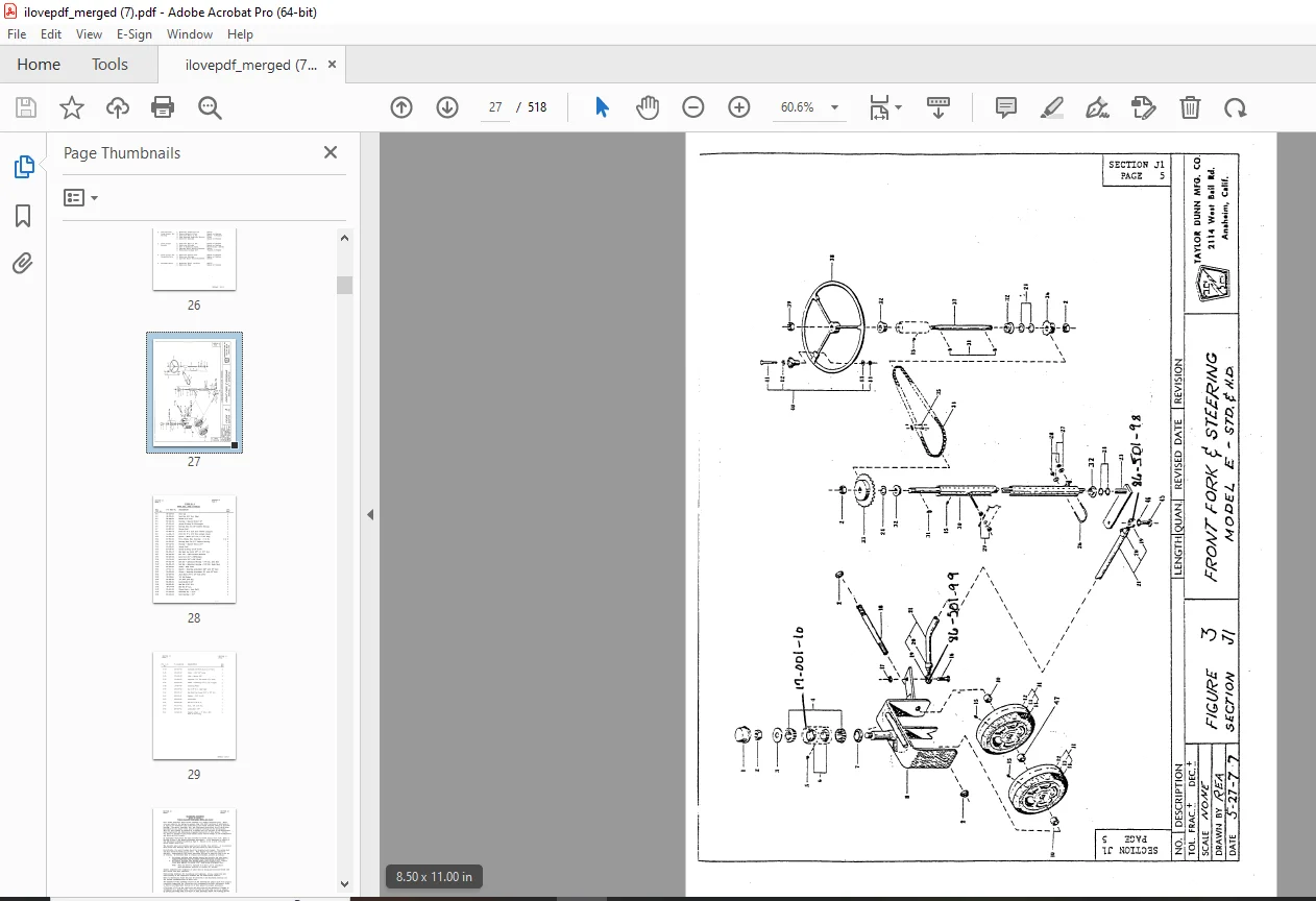
Section J1: Front Axle, Fork, Steering and Tires – Maintenance Procedures 23
Section J2: “Power Traction” Rear Axle, Motor and Brakes – Maintenance Procedures 30
Section J2M: Electric Motors – Maintenance, Service and Adjustment 45
Section J4: Mechanical Control Linkage – Maintenance Procedures 50
Section J5: Forward/Reverse Control Switch – Maintenance Procedures 55
Section J6: Master Control Program Switch – Maintenance, Service and Parts 62
Section J7: Speed Control Program Switch – Maintenance Procedures 73
Section J8: Batteries – Maintenance Procedures 83
Section J9: Body and Trim – Maintenance and Parts List 91
Notice of Changes 93
ME-450-01 Operation and Maintenance Manual with Part List 94
Table of Contents 95
Important Information 96
Section A: Inspection, Safety, and Introduction 97
Section B: Operating Instructions 99
Section C: 90 Day Warranty105
Section D: Maintenance Guide Checklist106
Section E: Lubrication Diagram107
Section F: Trouble Shooting Procedures108
Section G: Wiring Diagram110
Section H: Parts Ordering Procedure112
Section I: Suggested Spare Parts List112
Section J1: Front Axle, Fork, Steering and Tires – Maintenance Procedures116
Section J2: “Power Traction” Rear Axle, Motor and Brakes – Maintenance Procedures123
Section J2M: Electric Motors – Maintenance, Service and Adjustment138
Section J4: Mechanical Control Linkage – Maintenance Procedures143
Section J5: Forward/Reverse Control Switch – Maintenance Procedures148
Section J6: Master Control Switch – Maintenance, Service and Parts151
Section J7: Speed Control Program Switch – Maintenance Procedures162
Section J8: Batteries – Maintenance Procedures172
Section J9: Body and Trim – Maintenance and Parts List180
PWR-TtRON 240350480 Table of Contents182
ME-450-02 Operation and Maintenance Manual with Part List209
Important Information210
Table of Contents211
Section 1: Inspection, Safety, and Introduction213
Section 3: Operating Instructions214
Section 4: Maintenance Guide Checklist220
Section 5: Lubrication Diagram222
Section 6: Trouble Shooting Procedures223
Section 7: Wiring Diagram225
Section 8: Parts Ordering Procedure226
Section 9: Suggested Spare Parts List227
Section 10: Front Axle, Steering and Tires – Maintenance Procedures229
Section 11: “Power Traction” Rear Axle, Motor and Brakes – Maintenance Procedures234
Section 12: Electric Motors – Maintenance, Service and Adjustment247
Section 13: Mechanical Control Linkage – Maintenance Procedures253
Section 14: Rheostat Speed Control – Maintenance Procedures258
Section 15: PWR-TRON II – Introduction265
Section 16: Optional Accessories281
Section 17: Batteries And Chargers – Maintenance Procedures282
Section 18: Body & Trim Parts Diagram291
Section 19: EV-1 SCR Control for Electric Vehicles293
Section 20: EV-1 SCR Control Accelerator Switch322
Section 21: 75-Ampere Electric Vehicle Control Contactors324
Notice of Change329
ME-450-03 Operation and Maintenance Manual with Part List330
Table of Contents331
Section 1: Inspection, Safety, and Introduction332
Section 2: Taylor-Dunn Limited 90 Warranty334
Section 3: Operating Instructions335
Section 4: Maintenance Guide Checklist342
Section 5: Lubrication Diagram344
Section 6: Trouble Shooting Procedures345
Section 7: Wiring Diagram347
Section 8: Parts Ordering Procedure348
Section 9: Suggested Spare Parts List349
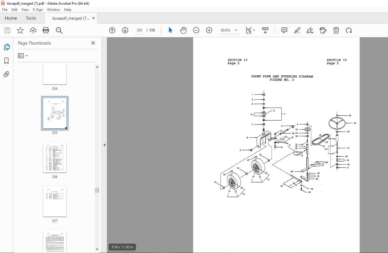
Section 10: Front Axle, Fork, Steering and Tires – Maintenance Procedures351
Section 11: “Power Traction” Rear Axle, Motor and Brakes – Maintenance Procedures358
Section 12: Electric Motors – Maintenance, Service and Adjustment375
Section 13: Mechanical Control Linkage – Maintenance Procedures379
Section 14: Speed Controller – Introduction385
Section 15: Optional Accessories402
Section 16: Batteries and Chargers403
Section 17: Body and Trim Parts415
EV-1 SCR Control for Electrical Vehicles417
Section 2: Module Settings by Vehicle447
Section 3: General Electric Service Information Bulletin448
Section 4: Wiring Diagrams452
Section 5: EV-1 Forward/Reverse Switch – Service and Adjustment457
Section 6: EV-1 SCR Control Accelerator Switch459
Section 7: 75-Ampere Electric Vehicle Control Contactors463
Section 8: 150- and 300- Ampere Electric Vehicle Control Contactors469
Section 9: EV-1 SCR Control Module – Diagram477
Section 10: EV-1 Suggested Spare Parts List479
Section 11: General Electric Parts481
Speed Controller Supplement482
Notice of Change505
Additional Diagrams507
DESCRIPTION:
Taylor-Dunn E 4-50 Operation & Maintenance With Parts Manual S.NO up 16000-75999 – PDF DOWNLOAD
- OPERATING INSTRUCTIONS SECTION: The controls on your Taylor-Dunn vehicle have been designed and located for convenience of operation and efficient performance Before driving your vehicle for the first time, familiarize yourself with each of the controls. Read the following instructions and with power OFF, operate each control. By following this suggestion you will attain a “feel” for their operation prior to traveling under power for the first time
- STEERING The steering wheel and steering system is similar to automotive types. Turn the steering wheel to the right (or clockwise) for a right turn and left (or counterclockwise) for a left turn.
- BRAKE-AUTOMATIC (DEADMAN): The foot treadle is a combination brake and accelerator .. It is designed for right foot operation and pivots near the center. Applying pressure with your heel controls the braking action. The greater the pressure applied with your heel the greater the braking action. A heavy spring control is automatically returns the ever the foot is removed. instructions.)
- ACCELERATOR PEDAL: incorporated with the treadle linkage and treadle to a brake applied position when( Refer to Safety Interlock for additional The same foot treadle is the accelerator control. Applying toe pressure to depress the treadle turns.power on to the drive motor. The amount of power delivered to the motor is controlled by the amount the treadle is depressed. Full power when fully depressed, and minimum power when partially depressed.
- SAFETY INTERLOCK & BRAKE PRESSURE RELEASE: (Foot Control) The pedal located on the left floor board controls the electric safety interlock. Power to the drive motor remains disconnected until the pedal is depressed. Releasing the pedal immediately shuts off all power to the drive motor. A second function of the pedal is to hold the automatic deadman brake spring pressure in a released position while operating the tractor. This feature has been added to reduce fatigue from constant heavy treadle pressure. To release spring pressure first depress accelerator treadle to full on position, next depress interlock pedal with left foot. Return accelerator treadle to off position. You will be able to feel the ease with which the accelerator now operates. Removing the left foot from the pedal immediately resets the brake spring pressure for positive braking action.
G.B 24/01/25