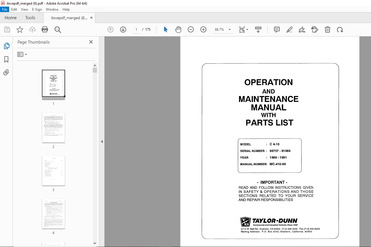
Taylor-Dunn C 4-10 Operation Maintenance With Parts Manual S.NO 86757-91988 PDF
$27.95
Taylor-Dunn C 4-10 Operation Maintenance With Parts Manual S.NO 86757-91988 – PDF DOWNLOAD
Description
Taylor-Dunn C 4-10 Operation Maintenance With Parts Manual S.NO 86757-91988 – PDF DOWNLOAD
FILE DETAILS:
Taylor-Dunn C 4-10 Operation Maintenance With Parts Manual S.NO 86757-91988 – PDF DOWNLOAD
Language : English
Pages : 175
Downloadable : Yes
File Type : PDF
IMAGES PREVIEW OF THE MANUAL:
TABLE OF CONTENTS:
Taylor-Dunn C 4-10 Operation Maintenance With Parts Manual S.NO 86757-91988 – PDF DOWNLOAD
MB-410-00 Operation and Maintenance Manual with Part List 1
Important Information 2
Table of Contents 3
Section 1: Inspection, Safety, and Introduction 4
Section 3: Operating Instructions 7
Section 4: Maintenance Guide Checklist 13
Section 5: Lubrication Diagram 15
Section 6: Trouble Shooting Procedures 16
Section 7: Important Facts on Batteries and Chargers 18
Section 8: Wiring Diagram 21
Section 9: Front Axle, Steering and Tires – Maintenance Procedures 22
Section 10: Power Traction – Maintenance, Service and Parts 30
Section 11: Hydraulic Disc Brake System – Maintenance Procedures 38
Section 12: Electric Motors – Maintenance, Service and Adjustment 46
Section 13: Suggested Spare Parts List 48
Section 14: PWR-TRON II – Introduction 49
Section 15: Parts Ordering Procedure 66
Section 16: Body and Trim – Maintenance Procedures 67
MB-410-01 Operation and Maintenance Manual with Part List 68
Table of Contents 69
Section 1: Introduction 75
Section 2: Vehicle Operation 83
Section 3: Schedule Maintenance 89
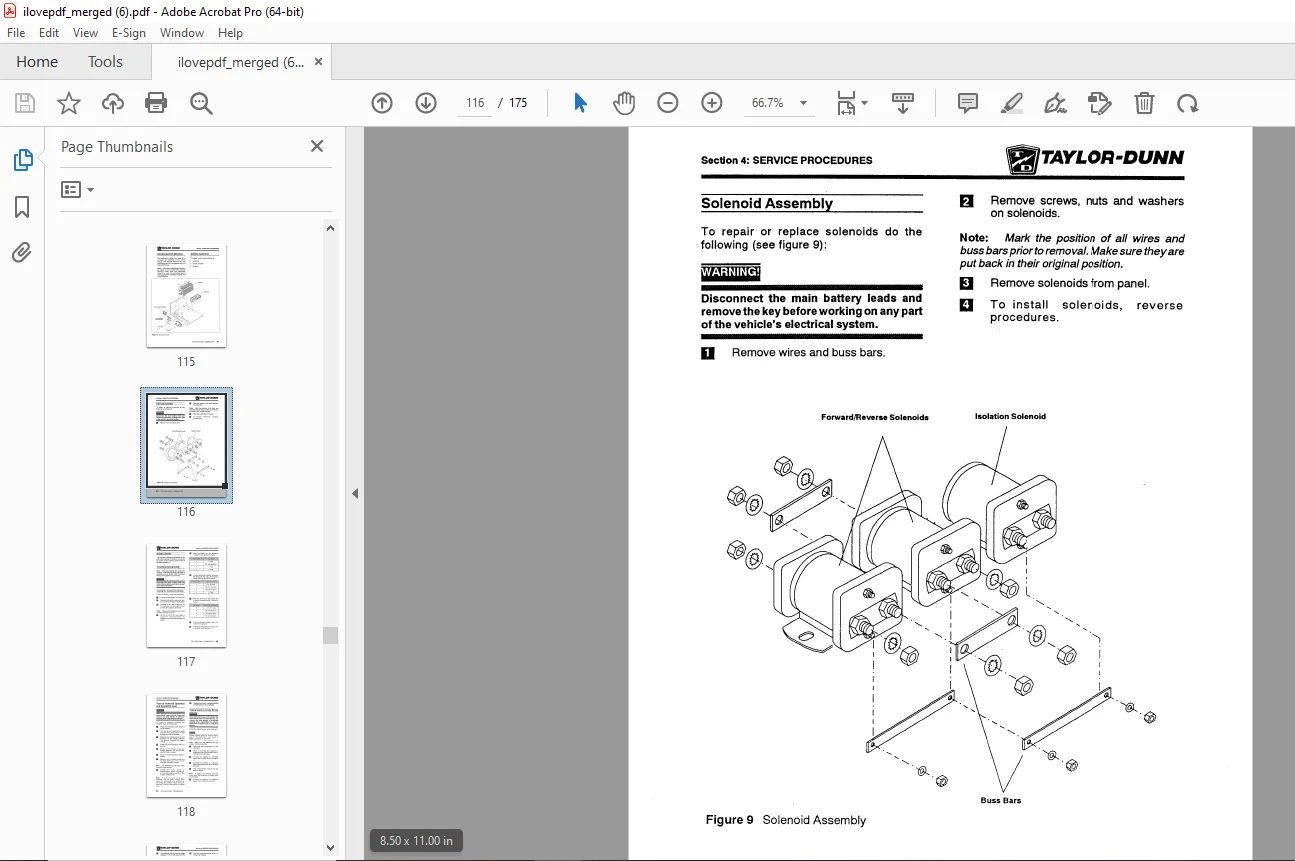
Section 4: Service Procedures 99
Section 5: Illustrated Parts Breakout139
DESCRIPTION:
Taylor-Dunn C 4-10 Operation Maintenance With Parts Manual S.NO 86757-91988 – PDF DOWNLOAD
OPERATING INSTRUCTIONS :
The controls on your Taylor-Dunn vehicle have been designed and located for convenience of operation and efficient performance. Before driving your vehicle for the first time, familiarize yourself with each of the controls. Read the following instructions and with power OFF, operate each control.
- STEERING: The steering wheel and steering system is similar to automotive types. Turn the steering wheel to the right (clockwise) for a right turn and left (counterclockwise) for a left turn.
- KEY LOCK :Your vehicle is equipped with a keyed lock located on the instrument panel. it is designed to lock the switch in the neutral position only. The key will remove from the lock in the locked position (neutral) only.
- SERVICE BRAKE (FOOT): The brake pedal is designed and located for right foot operation. It is the pedal located to the left of the accelerator pedal. It functions the same as the brake pedal in your automobile. Depressing the pedal applies the braking action. The greater the effort applied to the pedal with your foot, the greater the braking action to your vehicle. Removing your foot from the pedal allows immediate release of the braking action to your vehicle.
- FORHARD\REVERSE SWITCH: The forward/reverse switch is located on the instrument panel. It is a rocker type switch. Depressing the upper part places the vehicle in forward. Depressing the lower portion full downward places the vehicle in reverse. Center position is off.
- CAUTION: The forward/reverse switch serves the same purpose as the transmission in your automobile. Treat it with the same respect and care. DO NOT SHIFT from forward to reverse or vice-versa while the vehicle is in motion, especially near top speed, this causes great strain to your entire vehicle and will eventually cause severe damage, complete loss of power and could cause an accident.
- ACCELERATOR PEDAL The accelerator pedal is located to the right of the brake pedal. It is designed feright foot operation similar to your automobile. Depressing the pedal turns the power on to the motor. It also controls the amount of power delivered t o t he motor . lihen driving your v e h i c 1 e you w i l l be a b 1 e to f e e l full power when accelerator is fully depressed and minimum power when only partially depressed. You will have the same control of power in beth directions of travel. Your forward/reverse switch determines the direction travel and your accelerator pedal controls the Seed.
- HORN BUTTON: The horn Dutton is located on the shelf to right of control panel. Depressing button sounds horn. Releasing button will immediately silence horn. LIGHT SWITCH ~ne light switch that controls headlamps and taillamps is located in the instrument console.
G.B 24/01/25