Taylor-Dunn B6-10 Operation & Maintenance Manual Parts Manual S.NO 83811 to 88106 PDF
$28.95
Taylor-Dunn B6-10 Operation & Maintenance Manual Parts Manual S.NO 83811 to 88106 – PDF DOWNLOAD
Description
Taylor-Dunn B6-10 Operation & Maintenance Manual Parts Manual S.NO 83811 to 88106 – PDF DOWNLOAD
FILE DETAILS:
Taylor-Dunn B6-10 Operation & Maintenance Manual Parts Manual S.NO 83811 to 88106 – PDF DOWNLOAD
Language : English
Pages : 354
Downloadable : Yes
File Type : PDF
IMAGES PREVIEW OF THE MANUAL:
TABLE OF CONTENTS:
Taylor-Dunn B6-10 Operation & Maintenance Manual Parts Manual S.NO 83811 to 88106 – PDF DOWNLOAD
MB-610-00 Operation and Maintenance Manual with Part List 1
Section 1: Inspection, Safety, and Introduction 2
Section 2: Taylor-Dunn Limited 90 Warranty 4
Section 3: B 6-10 Operating Instructions 5
Section 4: Maintenance Guide Checklist 11
Section 5: Wiring Diagram 13
Section 6: Trouble Shooting Procedures 14
Section 7: Batteries – Maintenance Procedures 16
Section 8: Front Axle, Steering and Tires – Maintenance Procedures 18
Section 9: Carburetor – Maintenance Procedures 26
Section 10: Power Train – Sheaves, Rear Axle and Transmission 33
Section 11: Brake System 43
Section 12: Engine 46
Section 13: Control Linkage, Accelerator, Hand Park Brake and Foot Brake Pedal – Maintenance Procedures 63
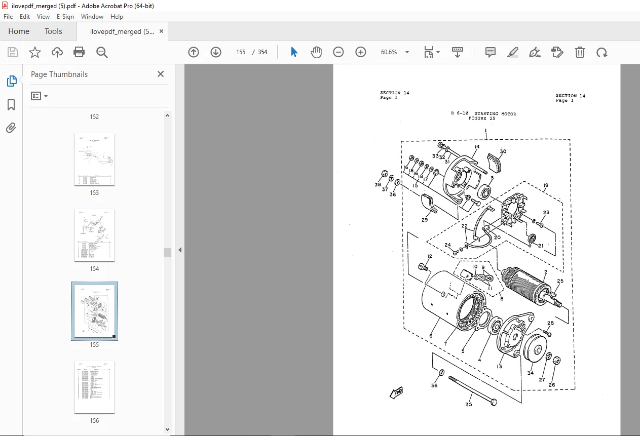
Section 14: Starting Motor 67
Section 15: Options and Kits 73
Section 16: Parts Ordering Procedure 75
Notice of Change 77
MB-610-01 Operation and Maintenance Manual with Part List 78
Important Information 79
Table of Contents 80
Section 1: Inspection, Safety, and Introduction 81
Section 3: B 6-10 Operating Instructions 84
Section 4: Maintenance Guide Checklist 90
Section 5: Wiring Diagram 93
Section 6: Trouble Shooting Procedures 94
Section 7: Batteries – Maintenance Procedures 96
Section 8: Front Axle, Steering and Tires – Maintenance Procedures 98
Section 9: Carburetor – Maintenance Procedures106
Section 10: Power Train Sheaves, Rear Axle and Transmission113
Section 11: Brake System131
Section 12: Engine134
Section 13: Control Linkage, Accelerator, Hand Park Brake and Foot Brake Pedal – Maintenance Procedures151
Section 14: Starting Motor155
Section 15: Options and Kits161
Section 16: Parts Ordering Procedure163
MB-610-02 Operation and Maintenance Manual with Part List165
Important Information166
Table of Contents167
Section 1: Inspection, Safety, and Introduction168
Section 2: Taylor-Dunn Limited 90 Warranty171
Section 3: B 6-10 Operating Instructions172
Section 4: Maintenance Guide Checklist179
Section 5: Wiring Diagram185
Section 6: Trouble Shooting Procedures186
Section 7: Batteries – Maintenance Procedures188
Section 8: Front Axle, Steering and Tires – Maintenance Procedures190
Section 9: Carburetor – Maintenance Procedures198
Section 10: Power – Train Sheaves, Rear Axle and Transmission206
Section 11: Brake System224
Section 12: Engine227
Section 13: Control Linkage, Accelerator, Hand Park Brake and Foot Brake Pedal – Maintenance Procedures244
Section 14: Starting Motor248
Section 15: Options and Kits254
Section 16: Parts Ordering Procedure256
Notice of Change258
Manual Supplement B 6-10 with G9A Engine259
MB-610-03 Operation and Maintenance Manual with Part List263
Table of Contents264
Section 1: Introduction270
Section 2: Vehicle Operation276
Section 3: Scheduled Maintenance284
Section 4: Service Procedures298
Section 5: Illustrated Parts Breakout314
DESCRIPITION:
Taylor-Dunn B6-10 Operation & Maintenance Manual Parts Manual S.NO 83811 to 88106 – PDF DOWNLOAD
OPERATING INSTRUCTIONS SECTION:
The controls on your Taylor-Dunn vehicle have been designed and located for convenience of operation and efficient performance. Before driving your vehicle for the first time, familiarize yourself with each of the controls. Read the following instructions and with power OFF, operate each control.
- STEERING The steering wheel and steering system is similar to automotive types. Turn the steering wheel to the ·right (clockwise) for a right turn and left (counterclockwise) for a left turn.
- KEY LOCK Your vehicle is equipped with a keyed lock located on the instrument panel. It is designed to lock the switch in the off position only. The key will remove from the lock in the off position only.
- SERVICE BRAKE (FOOT) The brake pedal is designed and located for right foot operation. It is the pedal located to the left of the accelerator pedal. It functions the same as the brake pedal in your automobile. Removing your foot from the pedal allows immediate release of the braking action to your vehicle.
- PARK BRAKE This is a hand lever actuated brake located between the front seats. Pulling brake directly up on the lever, sets park brake. Depressing handle button letting down on handle releases brake.
- CHOKE KNOB Use the choke knob (located on kick panel) when starting a cold engine. Pull out the choke knob and hold it in position until the engine responds correctly. Release choke as engine warms up.
- FORWARD/REVERSE SWITCH The forward/reverse switch is located on the kick panel. It is a lever type switch. Pu11ing the lever places the vehicle in forward. Pushing downward places vehicle in reverse. Center position is off.
- CAUTION: The forward/reverse switch serves the same purpose as the transmission SELECTOR in your automobile. Treat it with the same respect and care. DO NOT SHIFT from forward to reverse or vice-versa while the vehicle is in motion.
- OIL WARNING LIGHT Located on instrument panel, it will glow when oil level is low.
- BACK UP BUZZER Whenever vehicle is in reverse position, warning buzzer will sound.
- ACCELERATOR The accelerator pedal is located to the right of the brake pedal. It is designed for right foot operation similar to your automobile. Your forward/reverse switch determines the direction of travel and your accelerator pedal controls the speed.
- HORN BUTTON The horn button is located on the cowl shelf to the right of the steering column. Depressing button sounds horn. Releasing button will immediately silence horn.
G.B 24/01/25