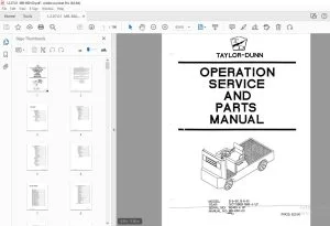
Taylor-Dunn B2-38,B2-48 Operation & Maintenance With Parts Manual PDF
$36.95
Taylor-Dunn B2-38 B2-48 Operation & Maintenance With Parts Manual S.NO 54833-74781 – PDF DOWNLOAD
Description
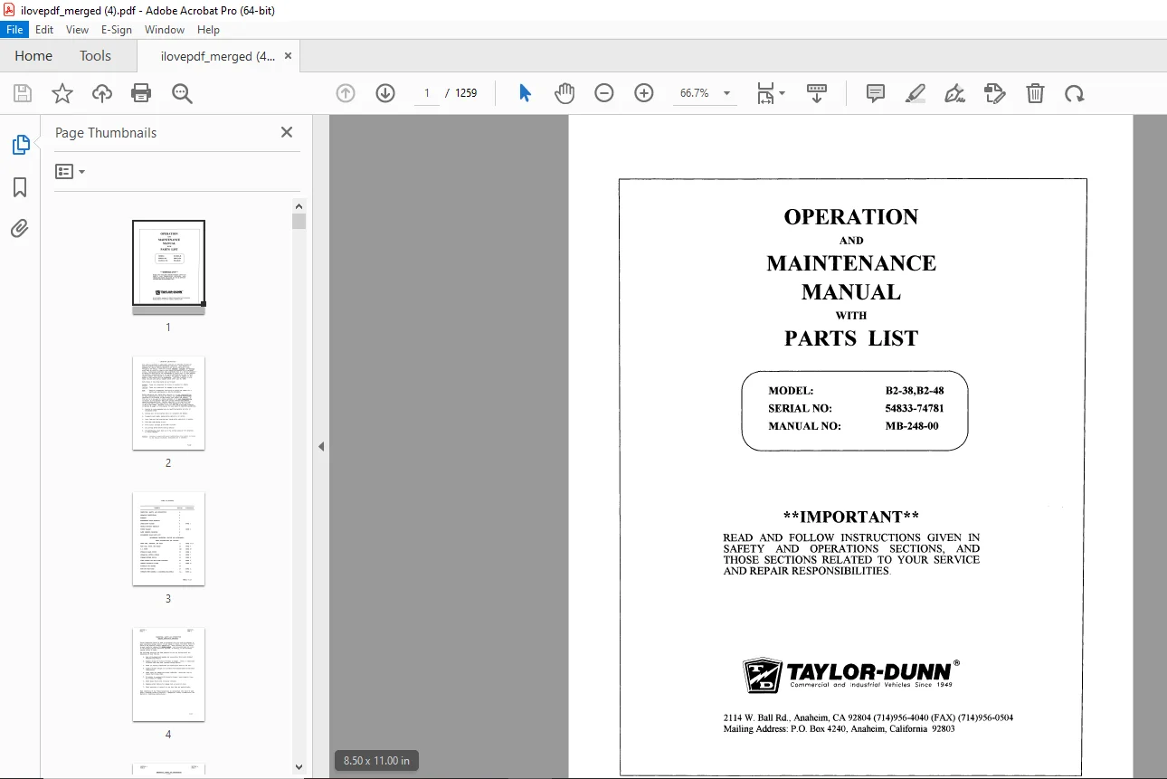
Taylor-Dunn B2-38,B2-48 Operation & Maintenance With Parts Manual S.NO 54833-74781 – PDF DOWNLOAD
FILE DETAILS:
Taylor-Dunn B2-38,B2-48 Operation & Maintenance With Parts Manual S.NO 54833-74781 – PDF DOWNLOAD
Language : English
Pages : 1259
Downloadable : Yes
File Type : PDF
IMAGES PREVIEW OF THE MANUAL:
TABLE OF CONTENTS:
MB-248-00 Operation and Maintenance Manual with Part List 1
Important Information 2
Table of Contents 3
Section A: Inspection, Safety, and Introduction 4
Section B: Operating Instructions 7
Section D: Maintenance Guide Checklist 13
Section E: Lubrication Diagram 15
Section F: Trouble Shooting Procedures 16
Section G: Wiring Diagram 18
Section H: Parts Ordering Procedure 19
Section I: Suggested Spare Parts List 20
Section J1: Front Axle, Fork, Steering and Tires – Maintenance Procedures 22
Section J1A: Steering Worm Assembly – Service and Adjustments 38
Section J2: Power Traction Rear Axle, Motor and Brakes – Maintenance Procedures 40
Section J2M: Electric Motors – Maintenance, Service and Adjustment 55
Section J3: Hydraulic Brake System – Maintenance Procedures 60
Section J4: Mechanical Control Linkage – Maintenance Procedures 66
Section J5: Forward/Reverse Control Switch – Maintenance Procedures 69
Section J6: Rheostat Speed Control – Maintenance Procedures 74
Section J7: General Electrical System – Maintenance Procedures 79
Section J8: Batteries – Maintenance Procedures 81
Section J9: Body and Trim – Maintenance Procedures 96
Section J1A: Steering Worm Assembly – Service and Adjustments 100
Notice of Change 103
Taylor-Dunn Limited 90 Day Warranty 105
MB-248-01 Operation and Maintenance Manual 106
Revision Log 108
MB-248-01 Operation and Maintenance Manual with Part List 109
Important Imformation 110
Table of Contents 111
Section 1: Inspection, Safety, and Introduction 112
Section 2: Taylor-Dunn Limited 90 Warranty 116
Section 3: Operating Instructions 117
Section 4: Maintenance Guide Checklist 126
Section 5: Lubrication Diagram 128
Section 6: Trouble Shooting Procedures 129
Section 7: Wiring Diagram 131
Section 8: Parts Ordering Procedure 132
Section 9: Suggested Spare Parts List 133
Section 10: Front Axle, Fork, Steering and Tires – Maintenance Procedures 135
Section 11: Power Traction – Maintenance, Service and Parts 156
Section 12: Electric Motors – Maintenance, Service and Adjustment 175
Section 13: Hydraulic Brake System – Maintenance Procedures 183
Section 14: Mechanical Control Linkage – Maintenance Procedures 193
Section 15: Forward/Reverse Switch – Maintenance Procedures 196
Section 16: Rheostat Speed Control – Maintenance Procedures 202
Section 17: PWR-TRON II – Introduction 207
Section 18: Electrical System Components – Maintenance Procedures 228
Section 19: Batteries – Maintenance Procedures 230
Section 20: Battery Charger – Maintenance, Service and Adjustment 235
Section 21: Body and Trim – Maintenance Procedures 250
Notice of Change 254
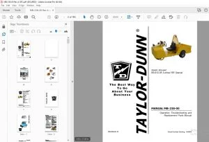
MB-210-02 Operation and Maintenance Manual 256
Important Information 257
Table of Contents 258
Section 1: Inspection, Safety, and Introduction 259
Section 2: Taylor-Dunn Limited 90 Warranty 262
Section 3: Operating Instructions 263
Section 4: Maintenance Guide Checklist 269
Section 5: Lubrication Diagram 271
Section 6: Trouble Shooting Procedures 272
Section 7: Wiring Diagram 274
Section 8: Parts Ordering Procedure 275
Section 9: Suggested Spare Parts List 276
Section 10: Front Axle, Fork, Steering and Tires – Maintenance Procedures 277
Section 11: “Power Traction” Rear Axle, Motor and Brakes – Maintenance Procedures 294
Section 12: Electric Motors – Maintenance, Service and Adjustment 308
Section 13: Hydraulic Brake System – Maintenance Procedures 315
Section 14: Mechanical Control Linkage – Maintenance Procedures 323
Section 15: Forward/Reverse Switch – Maintenance Procedures 326
Section 16: Rheostat Speed Control – Maintenance Procedures 330
Section 17: PWR-TRON II – Introduction 334
Section 18: Electrical System Components – Maintenance Procedures 354
Section 19: Batteries – Maintenance Procedures 356
Section 20: Charger – Maintenance, Service and Adjustment 360
Section 21: Body and Trim – Maintenance Procedures 372
MB-248-03 Operation and Maintenance Manual with Part List 375
Important Information 376
Table of Contents 377
Section 1: Inspection, Safety, and Introduction 378
Section 2: Taylor-Dunn Limited 90 Warranty 381
Section 3: Operating Instructions 382
Section 4: Maintenance Guide Checklist 388
Section 5: Lubrication Diagram 390
Section 6: Trouble Shooting Procedures 391
Section 7: Wiring Diagram 393
Section 8: Parts Ordering Procedure 394
Section 9: Suggested Spare Parts List 395
Section 10: Front Axle, Fork, Steering and Tires – Maintenance Procedures 396
Section 11: “Power Traction” Rear Axle, Motor and Brakes – Maintenance Procedures 413
Section 12: Electric Motors – Maintenance, Service and Adjustment 427
Section 13: Hydraulic Brake System – Maintenance Procedures 434
Section 14: Mechanical Control Linkage – Maintenance Procedures 441
Section 15: PWR-TRON II – Introduction 445
Section 16: Rheostat Speed Control – Maintenance Procedures 463
Section 15: Forward/Reverse Switch – Maintenance Procedures 467
Section 18: Electrical System Components – Maintenance Procedures 471
Section 19: Batteries – Maintenance Procedures 473
Section 20: Charger – Maintenance, Service and Adjustment 477
Section 21: Body and Trim – Maintenance Procedures 489
Revision Log 492
MB-248-04 Operation, Service, and Parts Manual 493
Important Information 494
Table of Contents 495
Section 1: Inspection, Safety, and Introduction 496
Section 2: Taylor-Dunn Limited 90 Warranty 499
Section 3: Operating Instructions 500
Section 4: Maintenance Guide Checklist 506
Section 5: Lubrication Diagram 508
Section 6: Trouble Shooting Procedures 509
Section 7: Wiring Diagram 511
Section 8: Parts Ordering Procedure 512
Section 9: Suggested Spare Parts List 513
Section 10: Front Axle, Fork, Steering and Tires – Maintenance Procedures 514
Section 11: “Power Traction” Rear Axle, Motor and Brake – Maintenance Procedures 531
Section 12: Electric Motors – Maintenance, Service and Adjustment 545
Section 13: Hydraulic Brake System – Maintenance Procedures 549
Section 14: Mechanical Control Linkage – Maintenance Procedures 556
Section 15: PWR-TRON II – Introduction 560
Section 16: Rheostat Speed Control – Maintenance Procedures 576
Section 17: Forward/Reverse Switch – Maintenance Procedures 580
Section 18: Electrical System Components – Maintenance Procedures 584
Section 19: Batteries – Maintenance Procedures 587
Section 20: Charger – Maintenance, Service and Adjustment 591
Section 21: Body and Trim – Maintenance Procedures 604
MB-248-05 Operation and Maintenance Manual and Parts List 607
Table of Contents 609
Section 1: Introduction 610
Section 2: Operating Guidelines 616
Section 3: Scheduled Maintenance and Service Procedures 622
Brakes 628
Front Axle/Steering 632
Drive Axle 638
Drive Motor 644
Batteries/Tires 646
Electrical System 650
Charging System 656
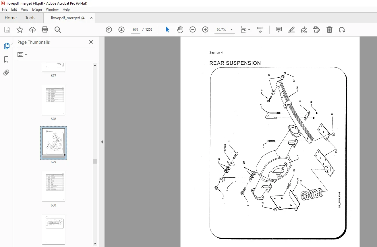
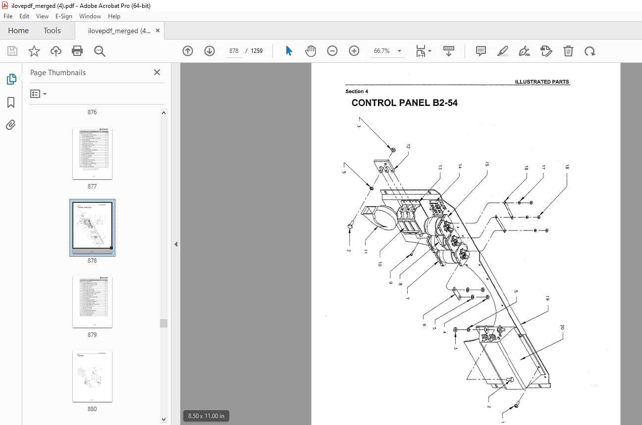
Section 4: Illustrated Parts List 660
3 Wheel Front Axle/Steering Supplement 700
EV-12 SCR Control Supplement 705
Section 3: General Electric Service Information Bulletin 707
Section 4: Wiring Diagram 711
Section 5: EV-1 Forward/Reverse Switch – Service and Adjustment 716
Section 6: EV-1 SCR Control Accelerator Switch 718
Section 7: 75-Ampere Electric-Vehicle Control Contactors 722
Section 8: 150- and 300-Ampere Electric-Vehicle Control Contactors 728
Section 9: EV-1 SCR Control Module Diagram 736
Section 10: Suggested Spare Parts List 738
MB-248-06 Operationand Maintenance Manual with Parts List 740
Table of Contents 741
Section 1: Introduction 749
Section 2: Safety Rules and Operational Information 755
Section 3: Maintenance and Service Procedures 763
Section 3A: B2-38 Three Wheel Front Axle/Steering Supplement 820
Sectoin 4: Illustrated Parts List 827
Optional and Misc Parts 883
MB-248-08 Operation, Service, and Parts Manual 896
Table of Contents 899
Introduction – Operation and Maintenance Manual 903
Section 1: Vehicle Description and Specifications 909
Section 2: Safety Rules and Operational Information 915
Section 3: Maintenance and Service Procedures 927
Section 4: Electrical and Charger Troubleshooting 995
Section 5: Illustrated Parts List Common1041
Appendix A1103
Appendix B1105
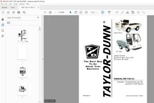
MB-248-09 Operation, Troubleshooting and Replacement Part1111
Operator and Maintenance Manual1112
Table of Contents1114
Section 1: Introduction1120
Section 2: Safety Rules and Operational Information1125
Section 3: Maintenance and Service Procedures1133
Section 3A: B2-38 Three Wheel Front Axle/Steering Supplement1185
Section 4: Illustrated Parts List1193
Appendix A – Special Tools1253
Appendix B – Torque Values1256
DESCRIPITION:
Taylor-Dunn B2-38,B2-48 Operation & Maintenance With Parts Manual S.NO 54833-74781 – PDF DOWNLOAD
OPERATING INSTRUCTIONS:
The controls on your Taylor-Dunn vehicle have been designed and located for convenience of operation and efficient performance. Before driving your vehicle for the first time, familiarize yourself with each of the controls. Read the following instructions and with power OFF, operate each control.
- STEERING The steering wheel and steering system is similar to automotive types. Turn the steering wheel to the right (clockwise) for a right turn and left (counterclockwise) for a left turn.
- KEY LOCK Your vehicle is equipped with a keyed lock located on the corner of forward reverse switch. It is designed to lock the switch in the neutral position only The key will remove from the lock in the locked position (neutral) only.
- PARK BRAKE (HAND) The hand parking brake is located in the right center of floor board. To engage hand brake, grasp top lever and pull towards rear, all the way, till hand lever stops. To release brake, push hand lever all the way forward.
- SERVICE BRAKE (FOOT) The brake pedal is designed and located for right foot operation. It is the pedal located to the left of accelerator pedal. It functions the same as the brake pedal in your a~obile. Depressing the pedal applies the braking action. The greater the effort applied to the pedal with your foot, the greater the braking action to your vehicle. Removing your foot from the pedal allows immediate release of the braking action to your vehicle.
- FORWARD/REVERSE SWITCH The forward/reverse switch is located to the right of the drivers seat. It is operated by the red handle. To place in forward position pull the red handle to the left towards the driver. To place in reverse position push the red handle to the right, away from the driver.
- CAUTION: The forward/reverse switch serves the same purpose as the transmission in your automobile. Treat it with the same respect and care. DO NOT SHIFT from forward to reverse or vice-versa while the vehicle is in ~ion. Shifting while in motion, especially near top speed, causes great strain to your entire vehicle and will eventually cause severe damage, complete loss of power and could cause an accident.
G.B 24/01/25