

Still Diesel Lpg Forklift Truck Type Rx70 22 Rx70 25 Rx70 30 Rx70 35 7321 7330 Service Manual
FILE DETAILS:
LANGUAGE:ENGLISH
PAGES:378
DOWNLOADABLE:YES
FILE TYPE:PDF
VIDEO PREVIEW OF THE MANUAL:

IMAGES PREVIEW OF THE MANUAL:

DESCRIPTION:
Still Diesel Lpg Forklift Truck Type Rx70 22 Rx70 25 Rx70 30 Rx70 35 7321 7330 Service Manual
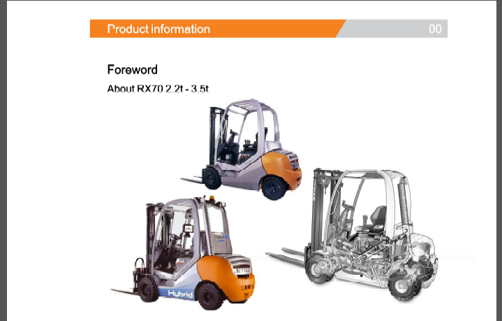
Foreword
• Ergonomic driver’s workplace Generation 2 mini-lever Generation 2 display operating unit
• Diesel-electric drive with three-phase AC technology Closed-loop AC drive technology Intelligent drive management for very low consumption Hydraulic fans and exhaust system with new air cooling duct
• Blue-Q
Characteristic curve optimisation of the drive
The following can be parameterised: switching off auxiliary consumers and enabling the consumption display
• Load measurement
• Lift mast vertical position
• Hydraulics blocking function in accordance with EN ISO 3691-1
Documentation
This workshop manual contains all the information required to assist the trained service engineers with all work, repairs and maintenance on this truck. In addition, some of the components have been deliberately excluded from this workshop manual and are explained elsewhere in order to ensure a clear overview. Changes may be made at short notice and at any time, and are communicated via Service Information documents.
The additional documentation comprises workshop manuals, special documentation and operating circuit diagrams.
Workshop manuals
• Display elements— display
• VW 1.9 ISDI/TDI (BTX/BEU)
• VW 2.0 ITDI (CBHA)
• VW2.0ISPI (BEF)
• FleetManager™
Special documentation
• Error list
• Overview of truck software
• STILL Flasher
• Overview of consumables
• FEM4.004 test log book
Operating circuit diagrams
• Seethe circuit diagram overview
TABLE OF CONTENTS:
Still Diesel Lpg Forklift Truck Type Rx70 22 Rx70 25 Rx70 30 Rx70 35 7321 7330 Service Manual
00 Product information
Foreword oo- 1
About RX702.2t – 3.5t 00- 1
Safety instructions 00- 3
Working on live electrical components 00- 3
Working on Hybrid components 00- 4
Jacking up the front of the truck 00- 4
Jacking up the rear of the truck 00- 5
Securing the fork carriage 00- 6
Maintenance 00- 9
Maintenance instructions 00- 9
Maintenance— 1000 hours/annually 00-11
Maintenance—3000 hours/every six months 00-13
Diagnostics 00-15
Measuring and testing equipment 00-15
Special tool 00-16
Standard torques 00-17
11 Electric motor
Traction motor 11- 1
General technical data 11- 1
Electrical connections 11- 1
Traction drive 11- 2
Traction motor 11- 4
Speed sensor 11- 6
Pin sensor 11- 6
Temperature sensor 11- 8
Temperature sensor KTY84 11- 8
Alternator 11-10
General technical data 11-10
Alternator 11-10
Alternator removal-installation 11-11
12 Internal combustion engine
Internal combustion engine 12- 1
Engine 12- 1
171866 [EN] VII
Engine unit Removal and installation 12- 3
Starter ring gear 12- 8
Starter motor 12- 9
Alternator 12-10
Alternator monitoring 12-11
Diesel engine 12-12
General technical data VW1.9ISDI 12-12
General technical data VW1.9ITDI 12-13
Diesel engineVW 1.91SDI/TDI 12-14
Engine control unitVW 1.91SDI/TDI 12-15
General technical dataVW 2.OITDI 12-18
Diesel engine VW2.0ITDI 12-19
LPGengine 12-21
General technical data VW2.0ISPI 12-21
VW LPG-2.0 litre BEF 12-23
Engine control unitVW 2.01SPI 12-24
13 Combustion engine—attachments
Air intake /filter 13- 1
Air intake 13- 1
Air filter 13-2
Cooling system 13- 4
Cooling circuit 13- 4
Coolant 13- 5
Checking, topping up and changing the coolant 13- 7
Radiator system 13- 9
Radiator Removal and installation 13-10
Fanwheel rotor -fan motor 13-11
Diesel fuel system 13-14
Fuelsystem 13-14
Fuel filter 13-14
Lowfuel warning threshold 13-15
LPGsystem 13-16
LPGsystem 13-16
Impcocomponents 13-17
Evaporatorfunction -gas mixer 13-18
Suction module 13-21
VIII 171866 [EN]
r
0B6 MAP/MATsensor 13-22
Chassis module 13-23
Actuator unit 13-24
Gas shut-off valve unit 13-25
Gas shut-off valve monitoring 13-25
Shut-down due to lack of gas 13-26
Maintenance and test specifications 13-27
Testing CO level in exhaust gases 13-28
Servicing the LPGfilter 13-29
Servicing the 30-bar excess pressure safety device 13-30
Evaporator- maintenance 13-31
Checking the evaporator for leaks 13-34
High-pressure relief valve – 1.7 bar 13-36
LPGcylinder/tank 13-37
LPG cylinder 13-37
14 Combustion engine—exhaust system
Exhaust system -diesel 14- 1
Exhaust system 14- 1
Exhaust system -particle filter 14- 2
General technical data – Eberspacher 14- 2
Structure of the Eberspacher particle filter 14- 3
7.5 kW Eberspacher particle filter 14- 3
Regeneration 14- 6
Maintenance instructions 14- 8
Exhaust system—LPG 14- 9
Lambda control system 14- 9
Lambdasensor 14-10
Three-way catalytic converter 14-12
22 Mechanical drive axle
Wheel drive 22- 1
Wheel drive 22- 1
Power unit 22- 4
General technical data Carraro 8.30 22- 4
Drive axle 22- 5
Removal and installation of the drive axle 22- 6
171866 [EN] IX
Table of contents
Differential gearbox 22-10
31 Chassis
Chassis 31- 1
Floorplate 31- 1
Counterweight 31- 2
Counterweight 31- 2
34 Driver’s compartment
Hood—covering—insulation 34- 1
Motor hood 34- 1
42 Steering system
Hydraulic steering 42- 1
General technical data 42- 1
Steering system 42- 2
Steering—error detection 42- 3
Steering unit 42- 4
Priority valve 42- 6
Steering wheel and steering column 42- i
Steering column 42- 7
Steering axle 42-11
General technical data 42- 11
Swing axle 42-12
Swing axle Removal and installation 42- 13
Wheel hub 42-15
Steering angle 42-18
Tie rod 42- 19
Axle stub 42-20
49 Brake system
Hydraulic service brake 49- 1
Service brake 49- 1
Brake sensor 1B2 49- 3
Parking brake 49- 5
Parking brake switch 1S3 49- 5
Parking brake 49- 6
X 171866 [EN]
r
50 Operating devices
Single pedal 50- 1
Accelerator -single-pedal 50- 1
Dual pedal 50- 4
Accelerator—dual pedal 50- 4
Operating devices 50- 7
Hand lever 50- 7
Joystick 50-8
Joystick operation 50-10
Generation 2 mini-lever 50-12
Generation 2 mini-leverActuation 50- 14
Tip switch 50-16
Generation 1mini-lever 50-18
Axle assignment 50-19
Direction indicator module (Fabli) 50-23
56 Display elements
Operating console 56- 1
Drive direction turn indicator display 56- 1
Display 56 3
Display operating unit (ABE 1) Generation 1 56- 3
ABE 1 Installation and removal 56- 5
Display operating unit (ABE 2) Generation 2 56- 6
ABE 2 Installation and removal 56- 8
60 Electrics/Electronics
General 60- 1
General technical data 60- 1
Overview of the controllers 60- 2
Overview of electrical components 60- 3
Software compatibility 60- 4
PAN process 60- 5
Parameter management 60- 6
Error ring buffer 60- 7
Insulation measurement 60- 7
Hybrid component insulation measurements 60- 11
Traction motortemperature monitoring 60-12
171866 [EN] XI
Drive mode—driving behaviourAvailability 60-13
Driving mode— driving behaviour Description 60- 14
Blue-Q = IQ 60-16
Wiring 60-18
CAN bus connections 60-18
Electrical system 60-20
Fuse box 60-20
Fuses 60-21
Relays 60-22
Sensor system 60-24
Vertical lift mast position 60-24
Tilt angle sensor 7B46 60-25
Tilt angle sensor parameters 60-27
Installation of the vertical lift mast position 60-28
Load measurement 60-31
Load measurement pressure sensor 60-33
Other components 60-35
Option board 60-35
CAN-Power-Port (CPP) 60-36
CPP 1/CPP3 60-36
CPP2/CPP4 60-37
CPP2B 60-38
Soot CPP (CPP5) 60-39
Relay-Power-Port 60-40
64 Electronic controllers
Truck control unit 64- 1
Truck Control Unit (TCU) 64- 1
Truck Contrail Unit (TCU) Removaland installation 64- 2
Converters 64- 4
Inverter 64- 4
Hybrid Iconverter 64- 6
ConvertersRemoval and installation 64- 7
Brake resistor 64-11
Hybrid components 64-13
Hybrid Ifunction 64-13
DC/DC converter 64-14
XII 171866 [EN]
r
DC/DC converter Removal and installation 64- 15
Storage module—energy accumulators 64-18
Storage module Removal and installation 64-20
Forcedventilation 64-21
69 Batteries and accessories
Starter battery 69- 1
Starter battery 69- 1
70 Hydraulics
General 70- 1
General technical data 70- 1
Lifting operating speeds 70- 2
Tilting operating speeds 70- 3
Lowering operating speeds 70- 4
Forward tilt safety test 70- 4
Lowering safety test 70- 5
Safety checks of hose assembly 70- 5
Depressurising the hydraulics 70- 6
Basic hydraulics 70- 8
Basic hydraulics 70- 8
Fan motor control unit 70-10
Fancontrol valve 70-11
Steering hydraulics 70-13
Operating hydraulics 70-15
Variable displacement pump 70-17
Hybrid I variable displacement pump 70-19
Pump regulator 70-20
Variable pump Removal and installation 70-21
Hydraulic tank 70-23
Hydraulic oil 70-23
Return filter 70-25
Breather 70-26
Suction filter 70-27
High-pressure filter 70-28
Conical nipple fittings (CNF) 70-29
Boltedjoint 70-29
171866 [EN] XIII
71 Operating hydraulics
Tilt cylinder 71- 1
Mast tilt 71- 1
Tilt cylinder Removal and installation 71- 2
Changing the set of seals 2200 -5000 kg 71- 3
Additional hydraulics 71- 6
Attachments 71- 6
Second operating function for attachments 71- 8
Clamp locking mechanism for hand levers 71- 8
76 Valves
Hand lever 76- 1
General technical data 76- 1
Hand lever valve block 76- 2
Valve block Removal/ installation 76- 3
Directional control valve block 76- 5
Check valve for hydraulics blocking function 76- 7
Hydraulic transmitter 76- 9
Servo hydraulics 76- 11
General technical data 76- 11
Servo hydraulics valve block 76-12
Directional control valve block 76-13
Directional control valve function Lifting 76-16
Directional control valve function Lowering 76-18
81 Lift mast
Lift mast 81- 1
General technical data 81- 1
Telescopic lift mast 81- 2
NiHo lift mast 81- 3
Triple mast 81- 4
Lift mast—removal 81- 6
Lift mast—installation 81- 8
Load chains 81- 1o
Load chains Checking, cleaning 81-10
Adjusting the load chains Telescopic mast 81-11
Adjusting the load chains NiHo lift mast 81-13
XIV 171866 [EN]
r
Outer load chain Triple mast 81-15
Middle load chain Triple mast 81-17
End position cushioning 81-20
End position damping of outer cylinder 81-20
Middle cylinder end dampener 81-21
Line breakage protection 81-22
Hosesafety valve of triplex mast 81-22
Shock valve installation positions 81-23
Lift cylinders 81-25
Liftjack 81-25
Outer cylinder 81-25
Centre cylinder 81-27
Cylinder head 81-28
Rollers/supporting rollers 81-31
Support roller clearance 81-31
84 Load support
Fork carriage 84- 1
Fork carriage 84- 1
Roller 84-2
Annex
X Circuit diagrams
Hydraulics X- 1
Hand lever until 12/2009 X- 1
Hand lever from 01/2010 X- 3
Servo hydraulics X- 5
171866
PLEASE NOTE:
- This is not a physical manual but a digital manual – meaning no physical copy will be couriered to you. The manual can be yours in the next 2 mins as once you make the payment, you will be directed to the download page IMMEDIATELY.
- This is the same manual used by the dealers inorder to diagnose your vehicle of its faults.
- Require some other service manual or have any queries: please WRITE to us at [email protected]


Braylon Jaime –
Easy to find the manual, easy to pay and easy to download!