Trusted Business
Verified & Licensed
Virus Free Files
100% Safe Downloads
Secure Payment
SSL Protected
Instant Delivery
Available Immediately
STA VH 250 / VH 350 SMALL TANDEMS WORKSHOP MANUAL – PDF DOWNLOAD
$30.95
STA VH 250 / VH 350 SMALL TANDEMS WORKSHOP MANUAL – PDF DOWNLOAD
Instant PDF Download
Available immediately
Save to Your Device
Download & keep forever
Antivirus Scanned
100% virus-free
Trusted Worldwide
175,000+ customers
Description
STA VH 250 / VH 350 SMALL TANDEMS WORKSHOP MANUAL – PDF DOWNLOAD
FILE DETAILS:
STA VH 250 / VH 350 SMALL TANDEMS WORKSHOP MANUAL – PDF DOWNLOAD
Language : English
Pages : 500
Downloadable : Yes
File Type : PDF
IMAGES PREVIEW OF THE MANUAL:
DESCRIPTION:
STA VH 250 / VH 350 SMALL TANDEMS WORKSHOP MANUAL – PDF DOWNLOAD
- Rollers VH250/270/300/350 are tandem vibration rollers with articulated frames and two smooth drums. Both drums are hydrostatically driven and vibrating. The vibration of the rear drum may be switched on and off. All functions of the machine are controlled by hydrostatic motors. The frames are designed to allow for soil compaction close to walls and curbs on both sides of the machine. Their small dimensions and turning radius make the machine suitable for work in limited areas.
- The operator’s station permits perfect visibility of both rims of the drums. The combined rollers VH250K and VH300K with front vibration drum. The two hydromotors drive and brake the rear axle with four smooth tyre.
- The roller should be used under conditions defined in the Czech Standard (CSN) IEC 721-2-1 (038900): WT, WDr, MWDr, i. e. in mild, dry warm and dry hot weather in the range of temperatures from -15 °C (5 °F) to 45 °C (113 °F).
- This machine is manufactured to the latest developments and standards, which secure its safe function. If the machine is used incorrectly, by untrained operators or for other purpose than stipulated above, there is a danger of an accident or damage to the equipment.
- The main purpose of this manual is to give information necessary for carrying out assembly and disassembly of the
machine as well as service repairs of main assemblies of the equipment. It contains technical and installation data,
instructions how to adjust the machine and how to use special tools, fixtures and aids. - The manufacturer continuously improves the products on the basis of experience and latest developments in the field.
- For this reason, the manufacturer may make some changes in drawings, descriptions and designs in this manual.
- Some expressions are used in the manual for better orientation, i. e. right, left, front, rear in the sense of the machine moving forward.
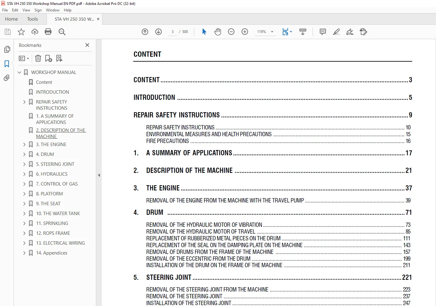
TABLE OF CONTENTS:
STA VH 250 / VH 350 SMALL TANDEMS WORKSHOP MANUAL – PDF DOWNLOAD
WORKSHOP MANUAL.........................................................  1
	Content ............................................................  3
	INTRODUCTION .......................................................  5
	REPAIR SAFETY INSTRUCTIONS .........................................  9
		REPAIR SAFETY INSTRUCTIONS ..................................... 10
		ENVIRONMENTAL MEASURES AND HEALTH PRECAUTIONS .................. 15
		FIRE PRECAUTIONS ............................................... 16
	1. A SUMMARY OF APPLICATIONS ....................................... 17
	2. DESCRIPTION OF THE MACHINE ...................................... 21
	3. THE ENGINE....................................................... 37
		Removal of the engine from the machine with the travel pump .... 39
	4. DRUM............................................................. 71
		Removal of the hydraulic motor of vibration .................... 73
		Removal of the hydraulic motor of travel ....................... 85
		Replacement of rubberized metal pieces on the drum .............111
		Replacement of the seal on the damping plate on the machine ....143
		Removal of drums from the frame of the machine .................157
		Removal of the eccentric from the drum .........................199
		Installation of the drum on the frame of the machine ...........211
	5. STEERING JOINT...................................................221
		Removal of the steering joint from the machine .................223
		Removal of the steering joint ..................................237
		Installation of the steering joint .............................247
	6. HYDRAULICS.......................................................259
		Removal of the travel pump and the clutch ......................261
		Removal of the pumps of vibration and of steering ..............279
		Removal of the oil cooler ......................................289
		Removal of steering hydraulic motor from the machine ...........303
		Removal of the steering hydraulic motor  .......................311
		Installation of the steering hydraulic motor ...................317
		Removal of power steering ......................................321
		Removal of the hydraulic tank ..................................327
		Replacement of the solenoid of vibration on the machine ........339
		Removal of the hydraulic loop filter ...........................343
		Replacement of filter cartridge and oil ........................347
		Disassembly of suction strainer.................................353
		Schematics of the hydraulic loop ...............................357
	7. CONTROL OF GAS...................................................361
		Removal of Bowden cable of gas control .........................363
		Removal of travel lever on the control panel ...................367
		Removal of travel pull rod .....................................375
	8. PLATFORM.........................................................385
		Removal of the platform ........................................387
		Removal of rubberized metal pieces of the platform .............393
	9. THE SEAT.........................................................401
		Removal of the switch on the seat ..............................403
	10. THE WATER TANK..................................................411
		Removal of the front tank from the frame of the machine ........413
		Removal of the rear tank from the frame of the machine .........417
	11. SPRINKLING......................................................423
		Removal of the sprinkling pump  ................................425
	12. ROPS FRAME......................................................429
		Removal of the protective ROPS frame ...........................431
	13. ELECTRICAL WIRING...............................................435
		Fuse box .......................................................439
		Batteries ......................................................443
		Exchange bulb...................................................447
		Scheme of the Electrical Installation ..........................453
	14. Appendices .....................................................459
		Test posts .....................................................461
		Towing the machine  ............................................463
		Troubleshooting ................................................473
		Table of tightening moments ....................................493
		List fixtures ..................................................497
Customer Support: [email protected]
https://vimeo.com/892836475?share=copy
S.S