STA Roller VH 850 & VH950 Tandem Vibratory Rollers Workshop Manual – PDF DOWNLOAD
$28.95
STA Roller VH 850 & VH950 Tandem Vibratory Rollers Workshop Manual – PDF DOWNLOAD
Description
STA Roller VH 850 & VH950 Tandem Vibratory Rollers Workshop Manual – PDF DOWNLOAD
FILE DETAILS:
STA Roller VH 850 & VH950 Tandem Vibratory Rollers Workshop Manual – PDF DOWNLOAD
Language : English
Pages : 210
Downloadable : Yes
File Type : PDF
IMAGES PREVIEW OF THE MANUAL:
DESCRIPTION:
STA Roller VH 850 & VH950 Tandem Vibratory Rollers Workshop Manual – PDF DOWNLOAD
1. INTRODUCTION
- This service manual consists of independent chapters dealing with both technical and assembling data, adjustment instructions and the guideline how to use special tools, jigs, fixtures and aids.
- The main purpose of this manual is to provide basic information for assembly, dismantling and service repairs of main assemblies of the machine.
- The unit assemblies are marked in this manual in the same way as in the spare parts catalogue. Before the dismounting, we recommend you to mark the parts disassembled keeping in mind the way how they will be put back and to blind all holes of the hydraulic system to prevent contamination of hydraulic circuits.
- During assembling the parts to the machine, tighten each bolt or nut according to the tightening torque table (Chapter 13.6.) if it is not stipulated otherwise in the text. Always follow safety regulations and measures shown in Chapter 2. The manufacturer is continuously improving his products on the basis of operational experience and latest developments. He, therefore, retains the right to make changes, on the basis of research and development, as compared with Figures, descriptions, procedures and designs given in this manual.
- Terms such as in the right-hand, left-hand, front or back are used in this manual for the customer’s information that means when the machine goes forward.
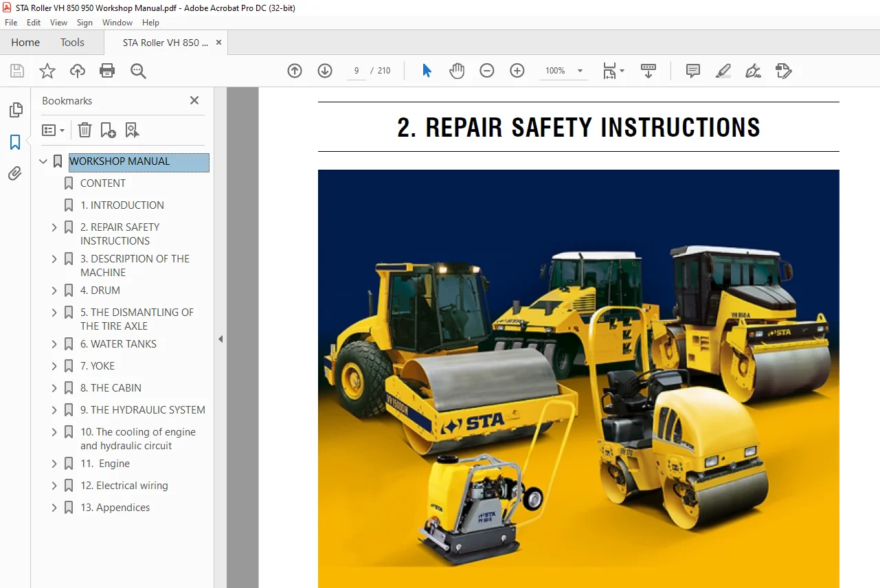
2.1. REPAIR SAFETY INSTRUCTIONS
THE FOLLOWING SAFETY INSTRUCTIONS MUST BE OBSERVED BY ALL REPAIRING THE MACHINE!
• Repairs may be carried out by skilled, trained and experienced personnel or dealer only and/or by STA service.
• When performing repairs, always use our shop manual. Special instructions for the assembly work are given in
individual chapters of the manual.
• Before putting the machine into operation acquaint yourselves with the machine control as given in the “Operator’s
Manual“ and make sure that you understand well all outfit of the machine.
• Do not use the machine if you do not fully understand all controls and until you know how the machine works.
• Know the area where you will work.
• Do not make any redesign or modifications on the machine because you could decrease safety of the equipment.
• Original parts and accessories have been designed especially for this machine.
• Installation and usage of spare parts not supplied by the manufacturer of the machine or not authorized by him can
have negative effects on operational characteristics and safety operation of the machine.
PRECAUTIONS WHEN REPAIRING AND INSPECTING THE EQUIPMENT
• Wear work clothe and boots.
• Use gloves when handling oils, fuel or coolant.
• Protect your eyes with goggles or a shield when handling the battery.
• Place the equipment on a flat and firm surface before starting repair. Secure the equipment against spontaneous
movement.
• Secure the frame of the equipment and the drum against mutual rotation using a safety pin and a draw bar.
• Before starting work remove the ignition key, disconnect the batteries and let hot parts cool down.
• Attach a warning note “Equipment out of work“ to the steering wheel and leave it there for the duration of service work.
• Wash the equipment thoroughly. If you use steam, do not expose electrical components and insulation directly to stem
jet, or else cover them beforehand.
• Keep all parts absolutely clean when dismantling, mounting, and servicing each assembly. Protect removed parts
from getting soiled.
• Clean the surface of dismantled parts and provide for adequately dust-free working conditions and a needed lay-off
area.
• Be careful when handling cleaning agents. Do not use petrol or other easy inflammable materials for cleaning.
• Dry the cleaned parts and immediately cover with anticorrosive protective oil- never install corroded parts!
• Tools, hoists, safety equipment of the supports, and other additional items must be serviceable and in good condition.
• Use hoists and fasteners (ropes, chains) that have sufficient carrying capacity and are in good condition.
• Make sure that there is enough fresh air supply when starting up the equipment in an enclosed area.
• Before placing the equipment into operation make sure there nobody on the equipment or close by. The start of the
equipment must always be announced with an audible alarm , also after any pause in operation before the equipment
is restarted. Persons present on the equipment and dangerously close by must leave the equipment after such alarm
has been sounded.
• Do not adjust moving equipment.
• When working (adjusting) on the running engine, avoid touching hot and rotating parts.. During work on the running
engine, another person must be present that can easily access the emergency switch and must be in contact at all
times with the person performing the adjustment, to be able to switch off the engine immediately when necessary.
• Use only prescribed makes of motor, gear and hydraulic oils and coolants.
TABLE OF CONTENTS:
STA Roller VH 850 & VH950 Tandem Vibratory Rollers Workshop Manual – PDF DOWNLOAD
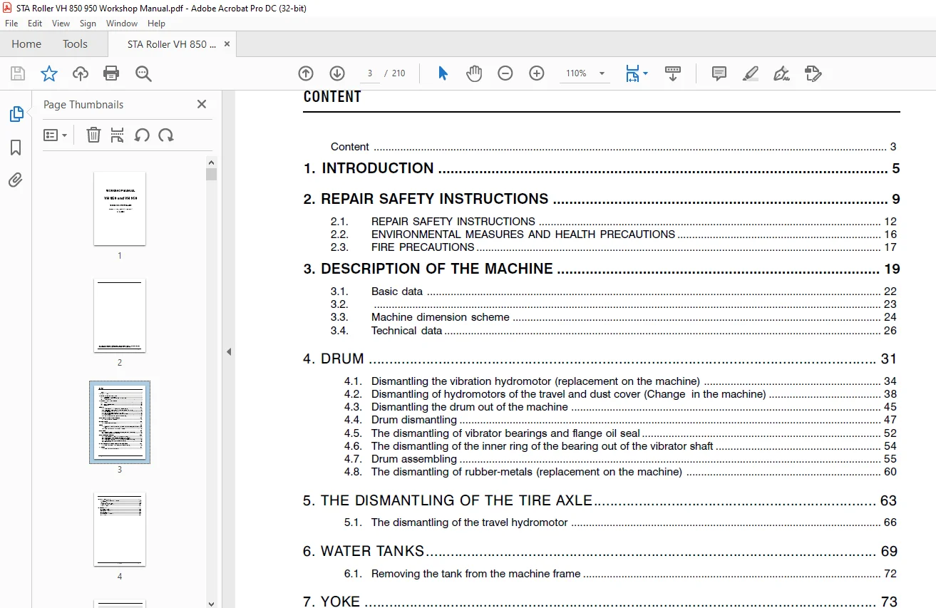
WORKSHOP MANUAL.............................................................................................................  1
	CONTENT ................................................................................................................  3
	1. INTRODUCTION ........................................................................................................  5
	2. REPAIR SAFETY INSTRUCTIONS ..........................................................................................  9
		2.1. Repair safety instructions .................................................................................... 12
		2.2. Environmental measures and health precautions ................................................................. 16
		2.3. Fire precautions .............................................................................................. 17
	3. DESCRIPTION OF THE MACHINE .......................................................................................... 19
		3.1. Basic data .................................................................................................... 22
		3.2. Machine design ................................................................................................ 23
		3.3. Machine dimension scheme ...................................................................................... 24
		3.4. Technical data ................................................................................................ 26
	4. DRUM................................................................................................................. 31
		4.1. DISMANTLING THE VIBRATION HYDROMOTOR (REPLACEMENT ON THE MACHINE).............................................. 34
		4.2. DISMANTLING OF HYDROMOTORS OF THE TRAVEL AND DUST COVER (CHANGE IN THE MACHINE)................................ 38
		4.3. DISMANTLING THE DRUM OUT OF THE MACHINE........................................................................ 45
		4.4. DRUM DISMANTLING............................................................................................... 47
		4.5. THE DISMANTLING OF VIBRATOR BEARINGS AND FLANGE OIL SEAL....................................................... 52
		4.6. THE DISMANTLING OF THE INNER RING OF THE BEARING OUT OF THE VIBRATOR SHAFT..................................... 54
		4.7. DRUM ASSEMBLING................................................................................................ 55
		4.8. THE DISMANTLING OF RUBBER-METALS (REPLACEMENT ON THE MACHINE).................................................. 60
	5. THE DISMANTLING OF THE TIRE AXLE..................................................................................... 63
		5.1. THE DISMANTLING OF THE TRAVEL HYDROMOTOR....................................................................... 66
	6. WATER TANKS.......................................................................................................... 69
		6.1. REMOVING THE TANK FROM THE MACHINE
FRAME...................................................................... 72
	7. YOKE................................................................................................................. 73
		7.1. REMOVAL THE YOKE FROM THE MACHINE FRAME, REPLACEMENT OF THE BEARING AND REPLACEMENT THE DRUM TURNING SENSOR.... 78
		7.2. REMOVAL OF THE FIRST YOKE SHAFT AND REPLACEMENT OF BEARINGS.................................................... 88
	8. THE CABIN............................................................................................................ 93
		8.1. REMOVING BOTH FRONT AND REAR RUBBER-METALS OF THE CABIN (REPLACEMENT ON THE MACHINE)........................... 96
		8.2. REMOVING THE CABIN OUT OF THE MACHINE FRAME....................................................................101
	9. THE HYDRAULIC SYSTEM.................................................................................................109
		9.1. DISMANTLING HYDROMOTORS FOR  STEERING AND LIFTING (PACKING REPLACEMENT)........................................114
		9.2. THE ASSEMBLY OF HYDROMOTORS FOR STEERING AND LIFTING (PACKING REPLACEMENT).....................................116
		9.3. DISMANTLING PUMPS OF TRAVEL AND  VIBRATION (REPLACEMENT ON THE MACHINE)........................................118
		9.4. DISMANTLING THE CLUTCH OF THE PUMP FOR TRAVEL AND VIBRATION (REPLACEMENT ON THE MACHINE).......................120
		9.5. DISMANTLING THE STEERING PUMP (REPLACEMENT ON THE MACHINE).....................................................121
		9.6. HYDRAULIC DIAGRAMS.............................................................................................123
	10. The cooling of engine and hydraulic circuit ........................................................................131
		10.1. Removal of the wather and of the oil cooler (replacement on the machine) .....................................134
	11.  Engine ............................................................................................................137
		11.1. Removal of the engine from the machine  ......................................................................140
	12. Electrical wiring ..................................................................................................143
		12.1. Layout of electric components in the machine .................................................................146
		12.2. Fuse box .....................................................................................................148
		12.3. Accumulator ..................................................................................................149
		12.4. Exchange bulbs headlights ....................................................................................150
		12.5. Exchange bulbs of dashboard ..................................................................................152
		12.6. Wiring diagram ...............................................................................................154
	13. Appendices .........................................................................................................157
		13.1. Measuring points .............................................................................................160
		13.2. Pulse sensors adjustment .....................................................................................162
		13.3. Vibration adjustment .........................................................................................166
		13.4. Towing .......................................................................................................167
		13.5. Troubleshooting ..............................................................................................176
		13.6. Table of tightening moments ..................................................................................204
		13.7. List fixtures ................................................................................................207
Questions? Email us: [email protected]
S.M