STA Roller VH 250 VH 350 SMALL TANDEMS WORKSHOP MANUAL – PDF DOWNLOAD
$30.95
STA Roller VH 250 VH 350 SMALL TANDEMS WORKSHOP MANUAL – PDF DOWNLOAD
Description
STA Roller VH 250 VH 350 SMALL TANDEMS WORKSHOP MANUAL – PDF DOWNLOAD
FILE DETAILS:
STA Roller VH 250 VH 350 SMALL TANDEMS WORKSHOP MANUAL – PDF DOWNLOAD
Language : English
Pages : 500
Downloadable : Yes
File Type : PDF
IMAGES PREVIEW OF THE MANUAL:
DESCRIPTION:
STA Roller VH 250 VH 350 SMALL TANDEMS WORKSHOP MANUAL – PDF DOWNLOAD
INTRODUCTION
- Rollers VH250/270/300/350 are tandem vibration rollers with articulated frames and two smooth drums. Both drums are hydrostatically driven and vibrating. The vibration of the rear drum may be switched on and off. All functions of the machine are controlled by hydrostatic motors. The frames are designed to allow for soil compaction close to walls and curbs on both sides of the machine. Their small dimensions and turning radius make the machine suitable for work in limited areas. The operator’s station permits perfect visibility of both rims of the drums.
- The combined rollers VH250K and VH300K with front vibration drum. The two hydromotors drive and brake the rear axle with four smooth tyre. The roller should be used under conditions defined in the Czech Standard (CSN) IEC 721-2-1 (038900): WT, WDr, MWDr, i. e. in mild, dry warm and dry hot weather in the range of temperatures from -15 °C (5 °F) to 45 °C (113 °F). This machine is manufactured to the latest developments and standards, which secure its safe function.
- If the machine is used incorrectly, by untrained operators or for other purpose than stipulated above, there is a danger of an accident or damage to the equipment. The main purpose of this manual is to give information necessary for carrying out assembly and disassembly of the machine as well as service repairs of main assemblies of the equipment. It contains technical and installation data, instructions how to adjust the machine and how to use special tools, fixtures and aids.
- The manufacturer continuously improves the products on the basis of experience and latest developments in the field. For this reason, the manufacturer may make some changes in drawings, descriptions and designs in this manual. Some expressions are used in the manual for better orientation, i. e. right, left, front, rear in the sense of the machine moving forward.
REPAIR SAFETY INSTRUCTIONS
THE FOLLOWING SAFETY INSTRUCTIONS MUST BE OBSERVED BY ALL REPAIRING THE
MACHINE!
• Repairs may be carried out by skilled, trained and experienced personnel only and/or by STA SERVICE.
• When performing repairs, always use our shop manual. Special instructions for the assembly work are given in
individual chapters of the manual.
• Before putting the machine into operation acquaint yourselves with the machine control as given in the “Operator’s
Manual“ and make sure that you understand well all outfit of the machine.
• Do not use the machine if you do not fully understand all controls and until you know how the machine works.
• Know the area where you will work.
• Do not make any redesign or modifications on the machine because you could decrease safety of the equipment.
• Original parts and accessories have been designed especially for this machine.
• Installation and usage of spare parts not supplied by the manufacturer of the machine or not authorized by him can
have negative effects on operational characteristics and safety operation of the machine.
SAFETY PRECAUTIONS WHEN REPAIRING AND INSPECTING THE EQUIPMENT
• Wear work clothe and boots.
• Use gloves when handling oils, fuel or coolant.
• Protect your eyes with goggles or a shield when handling the battery.
• Place the equipment on a flat and firm surface before starting repair. Secure the equipment against spontaneous
movement.
• Secure the frame of the equipment and the drum against mutual rotation using a safety pin and a draw bar.
• Before starting work remove the ignition key, disconnect the batteries and let hot parts cool down.
• Attach a warning note “Equipment out of work“ to the steering wheel and leave it there for the duration of service work.
• Wash the equipment thoroughly. If you use steam, do not expose electrical components and insulation directly to stem
jet, or else cover them beforehand.
• Keep all parts absolutely clean when dismantling, mounting, and servicing each assembly. Protect removed parts
from getting soiled.
• Clean the surface of dismantled parts and provide for adequately dust-free working conditions and a needed lay-off
area.
• Be careful when handling cleaning agents. Do not use petrol or other easy inflammable materials for cleaning.
• Dry the cleaned parts and immediately cover with anticorrosive protective oil- never install corroded parts!
• Tools, hoists, safety equipment of the supports, and other additional items must be serviceable and in good condition.
• Use hoists and fasteners (ropes, chains) that have sufficient carrying capacity and are in good condition.
• Make sure that there is enough fresh air supply when starting up the equipment in an enclosed area.
• Before placing the equipment into operation make sure there nobody on the equipment or close by. The start of the
equipment must always be announced with an audible alarm , also after any pause in operation before the equipment
is restarted. Persons present on the equipment and dangerously close by must leave the equipment after such alarm
has been sounded. Sound and hand signals and beacons must be also used as specified in the ČSN 27 7012
Standards, Appendix 1.
• Do not adjust moving equipment
TABLE OF CONTENTS:
STA Roller VH 250 VH 350 SMALL TANDEMS WORKSHOP MANUAL – PDF DOWNLOAD
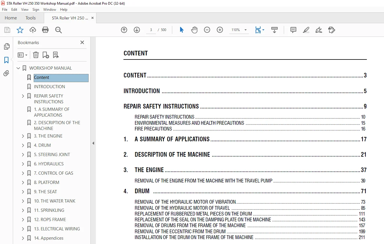
WORKSHOP MANUAL.........................................................  1
	Content ............................................................  3
	INTRODUCTION .......................................................  5
	REPAIR SAFETY INSTRUCTIONS .........................................  9
		REPAIR SAFETY INSTRUCTIONS ..................................... 10
		ENVIRONMENTAL MEASURES AND HEALTH PRECAUTIONS .................. 15
		FIRE PRECAUTIONS ............................................... 16
	1. A SUMMARY OF APPLICATIONS ....................................... 17
	2. DESCRIPTION OF THE MACHINE ...................................... 21
	3. THE ENGINE....................................................... 37
		Removal of the engine from the machine with the travel pump .... 39
	4. DRUM............................................................. 71
		Removal of the hydraulic motor of vibration .................... 73
		Removal of the hydraulic motor of travel ....................... 85
		Replacement of rubberized metal pieces on the drum .............111
		Replacement of the seal on the damping plate on the machine ....143
		Removal of drums from the frame of the machine .................157
		Removal of the eccentric from the drum .........................199
		Installation of the drum on the frame of the machine ...........211
	5. STEERING JOINT...................................................221
		Removal of the steering joint from the machine .................223
		Removal of the steering joint ..................................237
		Installation of the steering joint .............................247
	6. HYDRAULICS.......................................................259
		Removal of the travel pump and the clutch ......................261
		Removal of the pumps of vibration and of steering ..............279
		Removal of the oil cooler ......................................289
		Removal of steering hydraulic motor from the machine ...........303
		Removal of the steering hydraulic motor  .......................311
		Installation of the steering hydraulic motor ...................317
		Removal of power steering ......................................321
		Removal of the hydraulic tank ..................................327
		Replacement of the solenoid of vibration on the machine ........339
		Removal of the hydraulic loop filter ...........................343
		Replacement of filter cartridge and oil ........................347
		Disassembly of suction strainer.................................353
		Schematics of the hydraulic loop ...............................357
	7. CONTROL OF GAS...................................................361
		Removal of Bowden cable of gas control .........................363
		Removal of travel lever on the control panel ...................367
		Removal of travel pull rod .....................................375
	8. PLATFORM.........................................................385
		Removal of the platform ........................................387
		Removal of rubberized metal pieces of the platform .............393
	9. THE SEAT.........................................................401
		Removal of the switch on the seat ..............................403
	10. THE WATER TANK..................................................411
		Removal of the front tank from the frame of the machine ........413
		Removal of the rear tank from the frame of the machine .........417
	11. SPRINKLING......................................................423
		Removal of the sprinkling pump  ................................425
	12. ROPS FRAME......................................................429
		Removal of the protective ROPS frame ...........................431
	13. ELECTRICAL WIRING...............................................435
		Fuse box .......................................................439
		Batteries ......................................................443
		Exchange bulb...................................................447
		Scheme of the Electrical Installation ..........................453
	14. Appendices .....................................................459
		Test posts .....................................................461
		Towing the machine  ............................................463
		Troubleshooting ................................................473
		Table of tightening moments ....................................493
		List fixtures ..................................................497
Questions? Email us: [email protected]
S.M