Sprinter 2004 VA Parts Manual – PDF DOWNLOAD
$31.95
Sprinter 2004 VA Parts Manual – PDF DOWNLOAD
Description
Sprinter 2004 VA Parts Manual – PDF DOWNLOAD
FILE DETAILS:
Sprinter 2004 VA Parts Manual – PDF DOWNLOAD
Language : English
Pages : 675
Downloadable : Yes
File Type : PDF
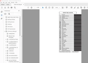
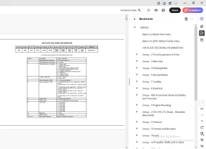
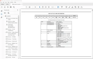
IMAGES PREVIEW OF THE MANUAL:
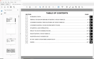
TABLE OF CONTENTS:
Sprinter 2004 VA Parts Manual – PDF DOWNLOAD
2004VA 1
Return to Model Year Index 0
Return to 2004 Vehicle Family Index 0
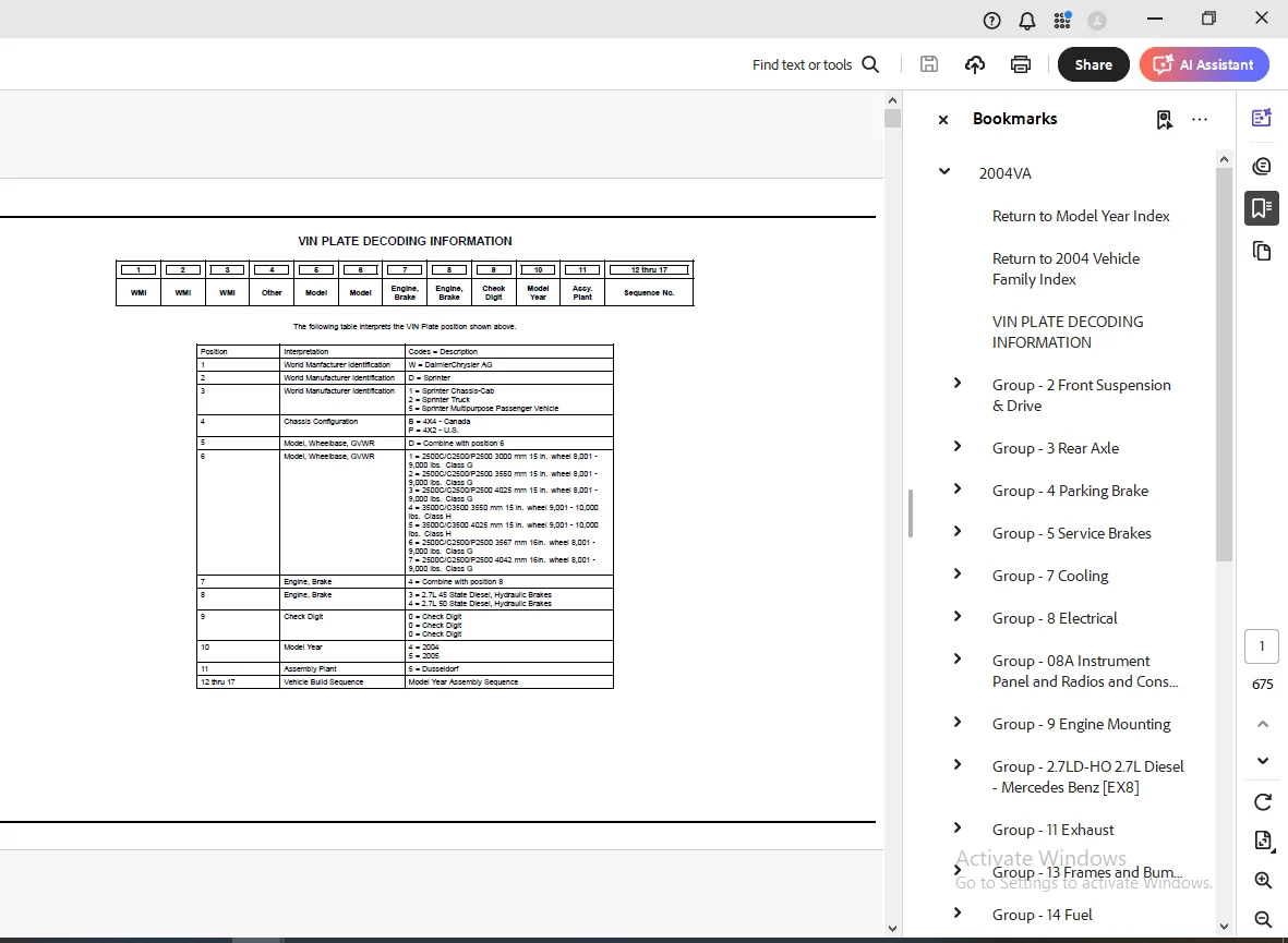
VIN PLATE DECODING INFORMATION 1
Group – 2 Front Suspension & Drive 2
Front Suspension 2
Fig 2-110 –> Front Control Arms, Knuckles, Bearings and Hubs 3
Fig 2-120 –> Front Shocks 5
Fig 2-130 –> Front Stabilzer Bar 7
Fig 2-140 –> Front Spring 9
Group – 3 Rear Axle 13
Rear Axle 13
Fig 3-110 –> Differential Assembly,Rear 14
Differential and Housing 0
Fig 3-210 –> Internal Differential Parts,Rear 15
Fig 3-220 –> Differential Housing,Rear 18
Fig 3-230 –> Axle Shaft and Wheel Bearings,Single Rear Wheels 20
Fig 3-240 –> Axle Shaft and Wheel Bearings,Dual Rear Wheels 21
Rear Axle Vent 0
Fig 3-310 –> Vent,Rear Axle 22
Group – 4 Parking Brake 23
Parking Brake Lever and Cables 23
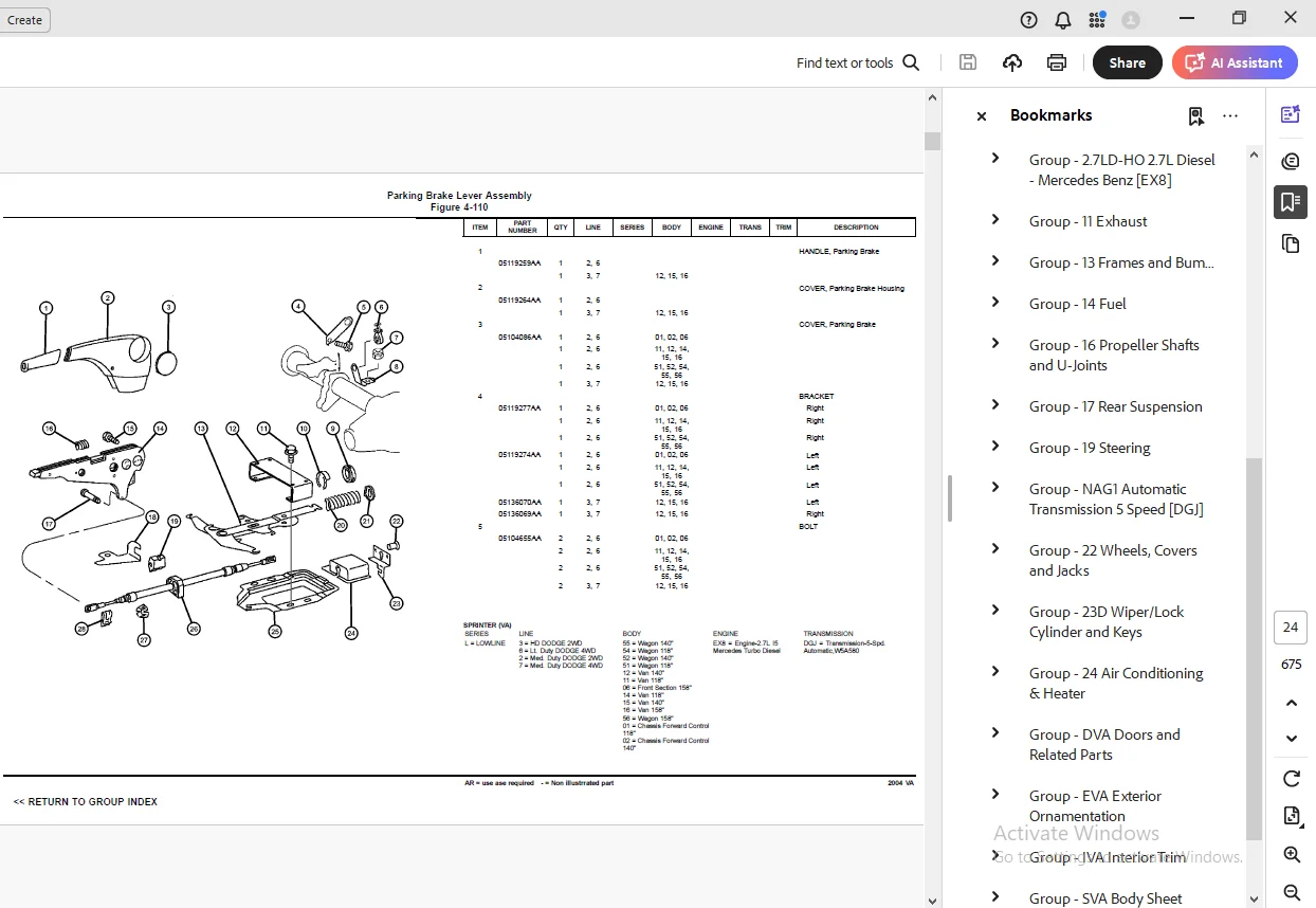
Fig 4-110 –> Parking Brake Lever Assembly 24
Fig 4-120 –> Parking Brake Assembly 30
Group – 5 Service Brakes 31
Front Brakes 31
Fig 5-110 –> Brakes, Front 32
Rear Brakes 0
Fig 5-210 –> Brakes,Rear,272MM 34
Fig 5-220 –> Brakes,Rear,285MM 36
Power Brake Booster 0
Fig 5-310 –> Booster 37
Fig 5-320 –> Vacuum Lines 38
Fig 5-330 –> Vacuum Reservoir 40
Brake Master Cylinder 0
Fig 5-410 –> Master Cylinder 41
Fig 5-420 –> Hydraulic Control Unit and ABS Module 44
Brake Lines and Hoses 46
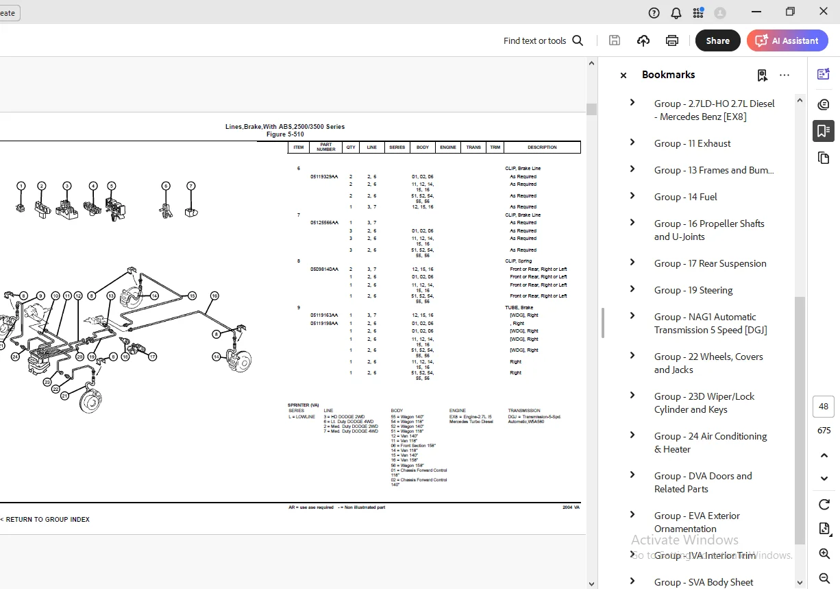
Fig 5-510 –> Lines,Brake,With ABS,2500/3500 Series 47
Fig 5-520 –> Brake, Power Regulator 54
Brake Pedals 56
Fig 5-610 –> Pedal Brake 57
Group – 7 Cooling 60
Radiator and Related Parts 60
Fig 7-110 –> Radiator And Related parts 61
Fig 7-120 –> Charge Air Intercooler 65
Water Pump and Related Parts 0
Fig 7-210 –> Water Pump And Related Parts 68
Pulleys and Related Parts 0
Fig 7-410 –> Drive pulleys 71
Drive Belts 72
Fig 7-510 –> Drive Belts 73
Lines, Transmission Oil Cooler 73
Fig 7-610 –> Oil Cooler Lines 74
Grilles 76
Fig 7-710 –> Grille And Related Parts 77
Group – 8 Electrical 78
Starters 79
Fig 8-105 –> Starters & Mounting 80
Alternators 0
Fig 8-205 –> Alternators (Generator) 81
Modules 0
Fig 8-405 –> Modules Seating Area 83
Fig 8-410 –> Modules and Related Parts 86
Fig 8-415 –> Module Back Up 91
Relays 91
Fig 8-505 –> Under Seat – Relays & Fuses 92
Fig 8-510 –> Instrument Panel – Relays & Fuses 98
Sensors103
Fig 8-605 –> Sensors Engine104
Fig 8-610 –> Sensors – Drivetrain107
Fig 8-615 –> Sensors – Brakes110
Fig 8-620 –> Sensor Ambient Temperature112
Single Board Engine Controllers112
Fig 8-715 –> Single Board Engine Controller (SBEC)113
Switches 0
Fig 8-805 –> Switches – Instrument Panel114
Fig 8-810 –> Switches -Steering Column121
Fig 8-815 –> Switches – Door123
Fig 8-820 –> Switch Brake125
Horns126
Fig 8-905 –> Horns & Alarm127
Battery Tray and Cables 0
Fig 8-1005 –> Battery Tray & Cables128
Lamps – Front, Rear and Courtesy 0
Fig 8-1105 –> Lamps – Front End137
Fig 8-1110 –> Lamps – Rear End143
Fig 8-1115 –> Lamps Rear End Cab and Chassis Vehicles148
Fig 8-1120 –> Lamps Interior Passenger Van150
Fig 8-1125 –> Lamps Interior Cargo Van152
Fig 8-1130 –> Lamp – Bulbs157
Wiring-Engine & Related Parts158
Fig 8-1210 –> Wiring – Engine159
Wiring-Headlamp to Dash 0
Fig 8-1305 –> Wiring – Headlamp & Dash161
Wiring-Instrument Panel164
Fig 8-1405 –> Wiring – Instrument Panel165
Wiring-Body & Accessories 0
Fig 8-1505 –> Wiring – Body & Accessories168
Wiring Repair173
Fig 8-1605 –> Connectors Engine Compartment174
Fig 8-1610 –> Connectors Body177
Fig 8-1615 –> Connectors Roof181
Fig 8-1620 –> Connectors Front Doors183
Fig 8-1625 –> Connectors Rear Doors186
Fig 8-1630 –> Connectors Seating Area188
Air Bag Systems189
Fig 8-1705 –> Air Bag System Drivers Side190
Fig 8-1710 –> Air Bag System Passenger Side193
Spark Plugs-Cables-Coils194
Fig 8-1910 –> Glow Plugs195
Group – 08A Instrument Panel and Radios and Consoles196
Instrument Panel196
Fig 08A-105 –> Instrument Panel197
Fig 08A-110 –> Instrument Panel Bezel and Related Parts202
Fig 08A-115 –> Ash Reciever and Glove Box208
Fig 08A-120 –> Instrument Panel Cover and Related Parts211
Fig 08A-125 –> Instrument Panel Reinforcement216
Instrument Panel Cluster217
Fig 08A-205 –> Instrument Panel Cluster218
Radio, Antenna, and Speakers219
Fig 08A-305 –> Radio220
Fig 08A-310 –> Antenna221
Fig 08A-315 –> Speakers223
Consoles224
Fig 08A-405 –> Console Cup Holder225
Group – 9 Engine Mounting227
Engine Mounting227
Fig 9-110 –> Engine Mounting228
Fig 9-120 –> Transmission Mounting229
Group – 27LD-HO 27L Diesel – Mercedes Benz [EX8]231
Engine Identification232
Fig 27LD-HO-110 –> Engine Assemblies233
Cylinder Head 0
Fig 27LD-HO-210 –> Cylinder Head, 27LD – H/O234
Fig 27LD-HO-220 –> Cylinder Head Cover, 27LD – H/O235
Cylinder Block 0
Fig 27LD-HO-310 –> Cylinder Block and Related Parts, 27L – H236
Crankshaft, Piston and Drive Plate 0
Fig 27LD-HO-410 –> Crankshaft and Pistons, 27L – H/O237
Camshafts and Valves 0
Fig 27LD-HO-510 –> Camshaft and Valves239
Timing Belt and Cover 0
Fig 27LD-HO-610 –> Timing Cover and Chain240
Fig 27LD-HO-620 –> Vaccum Pump242
Engine Oiling 0
Fig 27LD-HO-710 –> Oil Pump243
Fig 27LD-HO-720 –> Oil Cooler & Filter244
Fig 27LD-HO-730 –> Oil Pan245
Fig 27LD-HO-740 –> Turbo, Oil Feed & Return Lines246
Manifolds 0
Fig 27LD-HO-810 –> Intake Manifold247
Fig 27LD-HO-820 –> Exhaust Manifold248
Crankcase Ventilation 0
Fig 27LD-HO-910 –> Crankcase Ventilation249
Group – 11 Exhaust250
Exhaust System250
Fig 11-110 –> Exhaust System251
Heat Shields 0
Fig 11-210 –> Heat Shields Exhaust255
Group – 13 Frames and Bumpers256
Frames256
Fig 13-105 –> Front Frame Rails257
Fig 13-110 –> Side Frame Rails and Crossmembers 2500263
Fig 13-120 –> Side Frame Rails and Crossmembers 3500267
Fig 13-130 –> Brackets, Frame To Body Supports270
Front Bumper and Fascia271
Fig 13-230 –> Bumper, Front272
Rear Bumper and Fascia 0
Fig 13-320 –> Bumper, Rear275
Trailer Tow 0
Fig 13-610 –> Rear Hitch277
Fig 13-620 –> Trailer Tow279
Group – 14 Fuel281
Tank, Fuel281
Fig 14-110 –> Fuel Tank282
Fuel Tank Filler Tube282
Fig 14-210 –> Fuel Tank Filler Tube283
Fuel Lines285
Fig 14-310 –> Fuel Lines286
Fig 14-320 –> Fuel Line and Filter291
Fuel Rail 0
Fig 14-410 –> Injection System [EX8]292
Fuel Pump and Sending Unit 0
Fig 14-510 –> Fuel Module293
Fuel Injection Pump & Turbo Charger294
Fig 14-610 –> Fuel Injection Pump [EX8]295
Fig 14-630 –> Turbo Charger296
Fig 14-635 –> Turbo Charger Heat Shield297
Air Cleaner298
Fig 14-810 –> Air Cleaner299
Accelerator Pedal303
Fig 14-1110 –> Accelerator Pedal304
Group – 16 Propeller Shafts and U-Joints305
Propeller Shaft305
Fig 16-120 –> Shaft,Propeller,Rear,2 Piece306
Fig 16-130 –> Shaft,Propeller,Rear,3 Piece309
Group – 17 Rear Suspension312
Rear Suspension312
Fig 17-110 –> Rear Shocks313
Fig 17-120 –> Rear Springs, 2500 Series317
Fig 17-130 –> Rear Springs, 3500 Series322
Rear Stabilizer 0
Fig 17-210 –> Stabilizer Bar,Rear323
Group – 19 Steering325
Steering Wheel325
Fig 19-110 –> Steering Wheel and Related326
Steering Column329
Fig 19-210 –> Column Steering and Related330
Steering Gear333
Fig 19-310 –> Gear – Steering334
Power Steering Pump335
Fig 19-510 –> Pump and Pulley, Steering336
Power Steering Hoses 0
Fig 19-710 –> Hoses Steering and Related337
Group – NAG1 Automatic Transmission 5 Speed [DGJ]342
Transmission Assembly342
Fig NAG1-110 –> Automatic Transmission343
Case and Extension343
Fig NAG1-210 –> Case and Related Parts344
Oil Pump 0
Fig NAG1-310 –> Pump, Oil346
Gear Train 0
Fig NAG1-410 –> Laminated Brake and Front Support – [B1]347
Fig NAG1-420 –> Gear Train, Front Planetary Clutch – [K-1]348
Fig NAG1-430 –> Carrier, Planetary – [K1] – [VPLS]349
Fig NAG1-440 –> Clutch – Output Shaft – [K2]350
Fig NAG1-450 –> Center & Rear Planetary Set – Output Shaft – [351
Fig NAG1-460 –> Clutch – [K3]352
Fig NAG1-470 –> Multiple Disc Brake – [B2 & B3]353
Fig NAG1-480 –> Multiple Disc Brake – [B2 & B3]354
Fig NAG1-490 –> Multiple Disc Brake – [B2 & B3]355
Valve Body 0
Fig NAG1-710 –> Electronic – Hydraulic Control356
Gearshift Controls 0
Fig NAG1-1210 –> Gear Shift Control357
Group – 22 Wheels, Covers and Jacks360
Wheels and Hardware360
Fig 22-120 –> Wheels And Hardware361
Jack Stowage 0
Fig 22-340 –> Jack and Stowage364
Spare Tire Stowage 0
Fig 22-430 –> Wheel, Spare367
Group – 23D Wiper/Lock Cylinder and Keys368
Lock Cylinders and Keys368
Fig 23D-105 –> Lock Cylinders & Components369
Windshield Wiper and Washer Systems 0
Fig 23D-205 –> Windshield Wiper & Washer372
Group – 24 Air Conditioning & Heater383
Air Conditioner and Heater Units383
Fig 24-130 –> Hevac Unit, Front384
Air Conditioner and Heater Plumbing393
Fig 24-250 –> Heat Exchanger and Plumbing394
Fig 24-260 –> Plumbing, Heater400
Fig 24-265 –> Plumbing, Heater with Auxiliary warm water Heate404
Fig 24-270 –> Plumbing, Air Conditioning408
Fig 24-280 –> Condenser, Fan Front415
Fig 24-285 –> Condenser, Fan Roof418
Fig 24-290 –> Auxiliary Warm Water Heater420
Air Conditioner and Heater Controls427
Fig 24-320 –> Control428
Air Conditioning Compressor428
Fig 24-420 –> Compressor and Mounting429
Air Ducts and Outlets430
Fig 24-630 –> Air Ducts And Outlets, Front431
Fig 24-640 –> Air Ducts And Outlets, Rear435
Fig 24-650 –> Ventilator, Roof Mounted437
Group – DVA Doors and Related Parts438
Front Door438
Fig DVA-110 –> Door, Front Shell And Hinges439
Fig DVA-120 –> Door, Front Glass And Regulator Handle443
Fig DVA-130 –> Door, Front Exterior Handle And Links448
Door, Sliding Cargo451
Fig DVA-320 –> Door, Sliding Cargo Glass452
Fig DVA-330 –> Door, Sliding Cargo Lock And Controls454
Door, Dual and Single Cargo458
Fig DVA-410 –> Door, Cargo Shell And Hinges459
Fig DVA-420 –> Door, Cargo Glass And Hardware465
Fig DVA-430 –> Door, Cargo Lock And Control470
Exterior Mirror474
Fig DVA-520 –> Mirrors, Exterior475
Group – EVA Exterior Ornamentation482
Nameplates482
Fig EVA-120 –> Nameplates And Decals483
Moldings and Ornamentation 0
Fig EVA-210 –> Exterior Moldings486
Group – IVA Interior Trim487
Headliner and Visor487
Fig IVA-110 –> Headliner, Low Roof488
Fig IVA-115 –> Headliner, High Roof492
Fig IVA-120 –> Sunvisors, Grabhandles, Shelf and Attaching Par497
Moldings, Scuff Plates501
Fig IVA-210 –> Inner Panels – Fabric502
Fig IVA-215 –> Inner Panels – Cab504
Fig IVA-220 –> Inner Panels – Plywood508
Fig IVA-221 –> Inner Panel, Hard Fiber509
Fig IVA-225 –> Inner Panels510
Fig IVA-230 –> Inner Paneling Window – Pillar In Cab512
Fig IVA-235 –> Cargo Retainers – Without Windows515
Fig IVA-240 –> Cargo Retainers – With Windows517
Fig IVA-245 –> Rear Pillar Inner Panel519
Fig IVA-250 –> Cowl Panel – Silencer522
Fig IVA-255 –> Partition Panel523
Fig IVA-260 –> Partition Wall and Sliding Door524
Carpet528
Fig IVA-310 –> Carpet – Floor529
Fig IVA-315 –> Floor Lining, Entry Paneling & Footrest532
Fig IVA-320 –> Floor – Rubber535
Fig IVA-330 –> Floor – Wooden539
Fig IVA-340 –> Insulation – Carpet544
Fig IVA-350 –> Insulation Floor546
Door Trim Panels-Front and Sliding 0
Fig IVA-410 –> Front Door Trim549
Fig IVA-420 –> Sliding Door Trim555
Fig IVA-430 –> Rear Dual Door Trim558
Front Seats and Attaching Parts559
Fig IVA-510 –> Front Seat – Venice560
Fig IVA-515 –> Front Seat – Santos563
Fig IVA-520 –> Front Seat – Catano566
Fig IVA-525 –> Front Seat – Attaching Parts568
Fig IVA-530 –> Front Seat – Attaching Parts – Riser575
Fig IVA-535 –> Front Seat – Attaching Parts577
Rear Seats578
Fig IVA-610 –> Rear Seat – 2 Passenger579
Fig IVA-615 –> Rear Seat – 3 Passenger581
Fig IVA-620 –> Attaching Parts – 3rd Passenger Seat583
Seat Belts-Front and Rear 0
Fig IVA-710 –> Seat Belt – Front587
Fig IVA-720 –> Seat Belt – Second Row590
Group – SVA Body Sheet Metal Except Doors591
Floor Pans592
Fig SVA-210 –> Front Floor Pan593
Fig SVA-220 –> Rear Floor Pan595
Plugs597
Fig SVA-310 –> Plugs598
Front Fenders602
Fig SVA-410 –> Front Fender603
Fig SVA-420 –> Fender Splash Guards606
Hood and Hood Release607
Fig SVA-510 –> Hood and Hood Release608
Cowl and Dash Panel612
Fig SVA-610 –> Cowl and Dash613
Fig SVA-620 –> Inner Paneling in Cab, Cowl615
Glass and Rear View MIrror617
Fig SVA-710 –> Windshield, Backlite and Rear View Mirror618
Fig SVA-720 –> Front Right Side Sliding Glass621
Fig SVA-730 –> Side Glass, Fixed623
Aperture Panel624
Fig SVA-810 –> Front Aperture, Inner, Left625
Fig SVA-820 –> Front Aperture, Outer, Left627
Fig SVA-830 –> Front Aperture, Inner, Right629
Fig SVA-840 –> Front Aperture, Outer, Right632
Quarter Panel and Pillars 0
Fig SVA-910 –> Right Side Cargo Door Pillars & Wheelhouse633
Fig SVA-920 –> Right Side Panels, Cargo636
Fig SVA-930 –> Right Side Panels, Wagon640
Fig SVA-940 –> Left Side Cargo Door Pillars & Wheelhouse642
Fig SVA-950 –> Left Side Panels, Cargo645
Fig SVA-960 –> Left Side Panels, Wagon647
Fig SVA-970 –> Rear Splash Shield651
Fig SVA-980 –> Rear Step Panel653
Fig SVA-990 –> Partition Wall & Load Protection Grill655
Roof Panels 0
Fig SVA-1110 –> Low Roof Panel657
Fig SVA-1120 –> High Roof Panel661
Sunroof 0
Fig SVA-1210 –> Manual Sunroof665
Fig SVA-1220 –> Fixed Sunroof668
Group – LBLS Labels All Vehicle Locations669
Interior669
Fig LBLS-105 –> Instrument Panel / Visors & Interior670
Under Hood671
Fig LBLS-205 –> Engine Compartment672
Doors673
Fig LBLS-305 –> Front / Side & Cargo674
Exterior 0
Fig LBLS-410 –> Fuel Door & Filler675
G.B 05/04/25