Sprinter 2002 VA Parts Manual – PDF DOWNLOAD
$31.95
Sprinter 2002 VA Parts Manual PDF DOWNLOAD
Description
Sprinter 2002 VA Parts Manual PDF DOWNLOAD
FILE DETAILS:
Sprinter 2002 VA Parts Manual PDF DOWNLOAD
Language : English
Pages : 630
Downloadable : Yes
File Type : PDF
IMAGES PREVIEW OF THE MANUAL:
TABLE OF CONTENTS:
Sprinter 2002 VA Parts Manual PDF DOWNLOAD
2002VA 1
Return to Model Year Index 0
Return to 2002 Vehicle Family Index 0
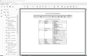
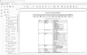
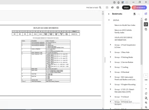
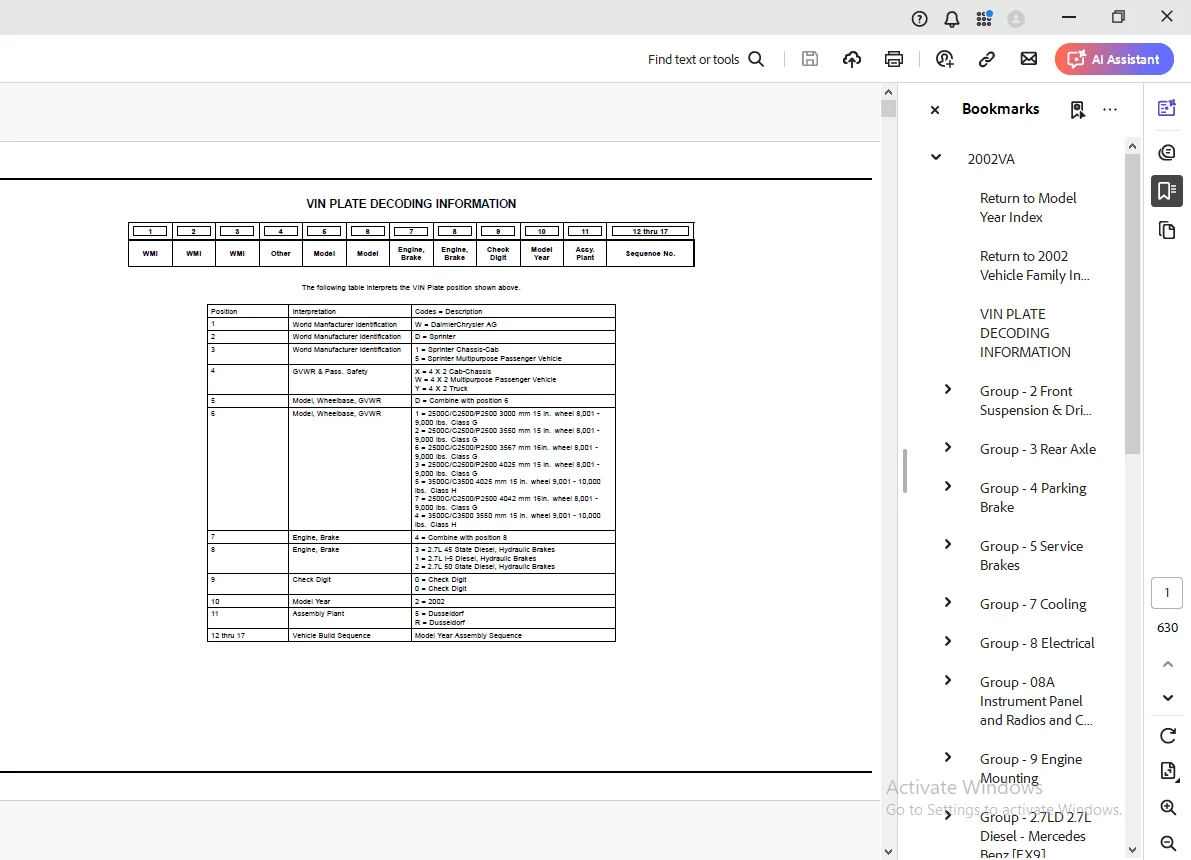
VIN PLATE DECODING INFORMATION 1
Group – 2 Front Suspension & Drive 2
Front Suspension 2
Fig 2-110 –> Front Control Arms, Knuckles, Bearings and Hubs 3
Fig 2-120 –> Front Shocks 5
Fig 2-130 –> Front Stabilzer Bar 7
Fig 2-140 –> Front, Spring 9
Group – 3 Rear Axle 12
Rear Axle 12
Fig 3-110 –> Differential Assembly,Rear 13
Differential and Housing 0
Fig 3-210 –> Internal Differential Parts,Rear 14
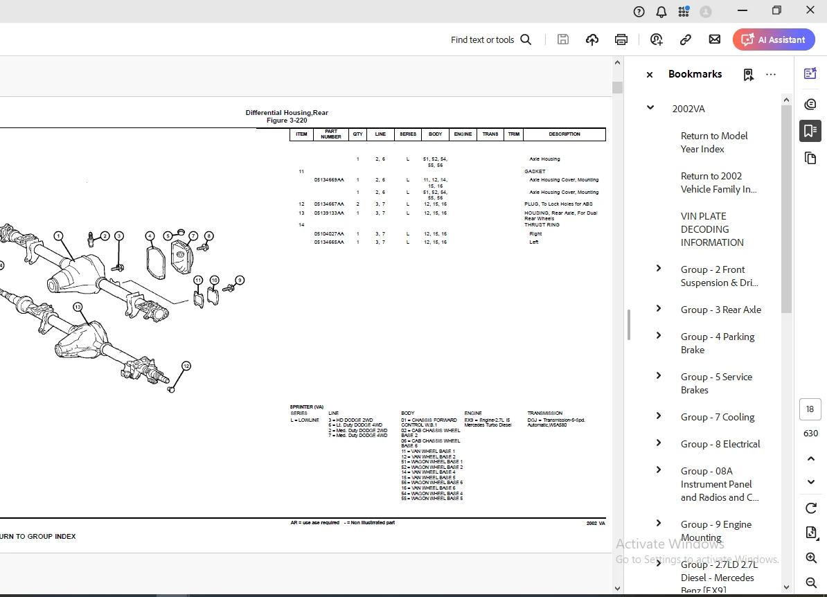
Fig 3-220 –> Differential Housing,Rear 17
Fig 3-230 –> Axle Shaft and Wheel Bearings,Single Rear Wheels 19
Fig 3-240 –> Axle Shaft and Wheel Bearings,Dual Rear Wheels 21
Rear Axle Vent 0
Fig 3-310 –> Vent,Rear Axle 22
Group – 4 Parking Brake 23
Parking Brake Lever and Cables 23
Fig 4-110 –> Parking Brake Lever Assembly 24
Fig 4-120 –> Parking Brake Assembly 30
Group – 5 Service Brakes 31
Front Brakes 31
Fig 5-110 –> Brakes, Front 32
Rear Brakes 0
Fig 5-210 –> Brakes,Rear,272MM 34
Fig 5-220 –> Brakes,Rear,285MM 36
Power Brake Booster 0
Fig 5-310 –> Booster 37
Fig 5-320 –> Vacuun Lines 38
Fig 5-330 –> Vacuum Reservoir 40
Brake Master Cylinder 0
Fig 5-410 –> Master Cylinder 41
Fig 5-420 –> Hydraulic Control Unit and ABS Module 44
Brake Lines and Hoses 45
Fig 5-510 –> Lines,Brake,With ABS,2500/3500 Series 46
Fig 5-520 –> Brake, Power Regulator 52
Brake Pedals 54
Fig 5-610 –> Pedal Brake 55
Group – 7 Cooling 58
Radiator and Related Parts 58
Fig 7-120 –> Radiator And Related parts 59
Fig 7-130 –> Charge Air Intercooler 63
Water Pump and Related Parts 65
Fig 7-210 –> Water Pump And Related Parts 66
Pulleys and Related Parts 0
Fig 7-410 –> Drive pulleys 68
Drive Belts 69
Fig 7-520 –> Drive Belts 70
Lines, Transmission Oil Cooler 0
Fig 7-610 –> Oil Cooler Lines 71
Grilles 73
Fig 7-710 –> Grille And Related Parts 74
Group – 8 Electrical 75
Starters 76
Fig 8-105 –> Starters & Mounting 77
Alternators 0
Fig 8-205 –> Alternators (Generator) 78
Modules 0
Fig 8-405 –> Modules Seating Area 79
Fig 8-410 –> Modules and Related Parts 82
Relays 85
Fig 8-505 –> Under Seat – Relays & Fuses 86
Fig 8-510 –> Instrument Panel – Relays & Fuses 91
Sensors 0
Fig 8-605 –> Sensors – Engine 96
Fig 8-610 –> Sensors – Drivetrain 98
Fig 8-615 –> Sensors – Brakes101
Fig 8-620 –> Sensor Ambient Temperature103
Single Board Engine Controllers103
Fig 8-715 –> Single Board Engine Controller (SBEC)104
Switches 0
Fig 8-805 –> Switches – Instrument Panel105
Fig 8-810 –> Switches -Steering Column111
Fig 8-815 –> Switches – Door113
Fig 8-820 –> Switch Brake115
Horns116
Fig 8-905 –> Horns & Alarm117
Battery Tray and Cables117
Fig 8-1005 –> Battery Tray & Cables118
Lamps – Front, Rear and Courtesy125
Fig 8-1105 –> Lamps – Front End126
Fig 8-1110 –> Lamps – Rear End132
Fig 8-1115 –> Lamps Interior Passenger Van137
Fig 8-1120 –> Lamps Interior Cargo Van139
Fig 8-1125 –> Lamp – Bulbs144
Wiring-Engine & Related Parts 0
Fig 8-1205 –> Wiring – Engine146
Wiring-Headlamp to Dash 0
Fig 8-1305 –> Wiring – Headlamp & Dash147
Wiring-Instrument Panel150
Fig 8-1405 –> Wiring – Instrument Panel151
Wiring-Body & Accessories153
Fig 8-1505 –> Wiring – Body & Accessories154
Wiring Repair159
Fig 8-1605 –> Connectors Engine Compartment160
Fig 8-1610 –> Connectors Body163
Fig 8-1615 –> Connectors Roof167
Fig 8-1620 –> Connectors Front Doors169
Fig 8-1625 –> Connectors Rear Doors172
Fig 8-1630 –> Connectors Seating Area174
Air Bag Systems175
Fig 8-1705 –> Air Bag System Drivers Side176
Fig 8-1710 –> Air Bag System Passenger Side178
Spark Plugs-Cables-Coils179
Fig 8-1910 –> Glow Plugs180
Group – 08A Instrument Panel and Radios and Consoles181
Instrument Panel181
Fig 08A-105 –> Instrument Panel182
Fig 08A-110 –> Instrument Panel Bezel and Related Parts186
Fig 08A-115 –> Ash Reciever and Glove Box191
Fig 08A-120 –> Instrument Panel Cover and Related Parts193
Fig 08A-125 –> Instrument Panel Reinforcement197
Instrument Panel Cluster197
Fig 08A-205 –> Instrument Panel Cluster198
Radio, Antenna, and Speakers198
Fig 08A-305 –> Radio199
Fig 08A-310 –> Antenna201
Fig 08A-315 –> Speakers203
Consoles204
Fig 08A-405 –> Console Cup Holder205
Group – 9 Engine Mounting206
Engine Mounting206
Fig 9-110 –> Engine Mounting207
Fig 9-120 –> Transmission Mounting208
Group – 27LD 27L Diesel – Mercedes Benz [EX9]210
Engine Identification211
Fig 27LD-110 –> Engine Assemblies212
Cylinder Head 0
Fig 27LD-210 –> Head, Cylinder213
Fig 27LD-220 –> Cover, Cylinder Head214
Cylinder Block 0
Fig 27LD-310 –> Cylinder Block and Related Parts215
Crankshaft, Piston and Drive Plate 0
Fig 27LD-410 –> Crankshaft and Pistons216
Camshafts and Valves 0
Fig 27LD-510 –> Camshaft and Valves218
Timing Belt and Cover 0
Fig 27LD-610 –> Timing Cover and Chain219
Fig 27LD-620 –> Vaccum Pump221
Engine Oiling 0
Fig 27LD-710 –> Oil Pump222
Fig 27LD-720 –> Oil Cooler and Filter223
Fig 27LD-730 –> Oil Pan224
Fig 27LD-740 –> Turbo, Oil Feed and Return Lines225
Manifolds 0
Fig 27LD-810 –> Intake Manifold226
Fig 27LD-820 –> Exhaust Manifold227
Crankcase Ventilation 0
Fig 27LD-910 –> Crankcase Ventilation228
Group – 11 Exhaust229
Exhaust System229
Fig 11-110 –> Exhaust System230
Heat Shields232
Fig 11-210 –> Heat Shields Exhaust233
Group – 13 Frames and Bumpers234
Frames234
Fig 13-105 –> Front Frame Rails235
Fig 13-110 –> Side Frame Rails and Crossmembers 2500239
Fig 13-120 –> Side Frame Rails and Crossmembers 3500241
Fig 13-130 –> Brackets, Frame To Body Supports242
Front Bumper and Fascia243
Fig 13-230 –> Bumper, Front244
Rear Bumper and Fascia 0
Fig 13-320 –> Bumper, Rear246
Trailer Tow 0
Fig 13-610 –> Rear Hitch248
Fig 13-620 –> Trailer Tow249
Group – 14 Fuel250
Tank, Fuel250
Fig 14-110 –> Fuel Tank251
Fuel Tank Filler Tube251
Fig 14-210 –> Fuel Tank Filler Tube252
Fuel Lines253
Fig 14-310 –> Fuel Lines254
Fig 14-320 –> Fuel Line and Filter258
Fuel Rail 0
Fig 14-410 –> Injection System [EX9]260
Fuel Pump and Sending Unit 0
Fig 14-510 –> Fuel Module261
Throttle Body262
Fig 14-610 –> Fuel Injection Pump [EX9]263
Fig 14-630 –> Turbo Charger264
Fig 14-635 –> Turbo Charger Heat Shield265
Air Cleaner266
Fig 14-810 –> Air Cleaner267
Accelerator Pedal270
Fig 14-1110 –> Accelerator Pedal271
Group – 16 Propeller Shafts and U-Joints272
Propeller Shaft272
Fig 16-110 –> Shaft,Propeller,Rear,2 Piece273
Fig 16-120 –> Shaft,Propeller,Rear,3 Piece276
Group – 17 Rear Suspension279
Rear Suspension279
Fig 17-110 –> Rear Shocks280
Fig 17-120 –> Rear Springs, 2500 Series283
Fig 17-130 –> Rear Springs, 3500 Series287
Rear Stabilizer 0
Fig 17-210 –> Stabilizer Bar,Rear288
Group – 19 Steering290
Steering Wheel290
Fig 19-110 –> Steering Wheel and Related291
Steering Column293
Fig 19-210 –> Column Steering and Related294
Steering Gear297
Fig 19-310 –> Gear – Steering298
Power Steering Pump299
Fig 19-510 –> Pump and Pulley, Steering300
Power Steering Hoses 0
Fig 19-710 –> Hoses Steering and Related301
Group – NAG1 Automatic Transmission 5 Speed [DGJ]305
Transmission Assembly305
Fig NAG1-110 –> Automatic Transmission306
Case and Extension 0
Fig NAG1-210 –> Case and Related Parts307
Oil Pump309
Fig NAG1-310 –> Pump, Oil310
Gear Train 0
Fig NAG1-410 –> Laminated Brake & Front Support – [B1]311
Fig NAG1-420 –> Gear Train, Front Planetary Clutch – [K1]312
Fig NAG1-430 –> Carrier, Planetary – [K1] – [VPLS]313
Fig NAG1-440 –> Clutch – Output Shaft – [K2]314
Fig NAG1-450 –> Center & Rear Planetary Set – Output Shaft – [315
Fig NAG1-460 –> Clutch – [K3]316
Fig NAG1-470 –> Multiple Disc Brake – [B2 & B3]317
Fig NAG1-480 –> Multiple Disc Brake – [B2 & B3]318
Fig NAG1-490 –> Multiple Disc Brake – [B2 & B3]319
Valve Body 0
Fig NAG1-710 –> Electronic – Hydraulic Control320
Gearshift Controls 0
Fig NAG1-1210 –> Gear Shift Control321
Group – 22 Wheels, Covers and Jacks324
Wheels and Hardware324
Fig 22-120 –> Wheels And Hardware325
Jack Stowage326
Fig 22-340 –> Jack and Stowage327
Spare Tire Stowage 0
Fig 22-430 –> Wheel, Spare330
Group – 23D Wiper/Lock Cylinder and Keys331
Lock Cylinders and Keys331
Fig 23D-105 –> Lock Cylinders & Components332
Windshield Wiper and Washer Systems334
Fig 23D-205 –> Windshield Wiper & Washer335
Group – 24 Air Conditioning & Heater342
Air Conditioner and Heater Units342
Fig 24-130 –> Hevac Unit, Front343
Air Conditioner and Heater Plumbing350
Fig 24-250 –> Heat Exchanger and Plumbing351
Fig 24-260 –> Plumbing, Heater357
Fig 24-265 –> Plumbing, Heater with Auxiliary warm water Heate361
Fig 24-270 –> Plumbing, Air Conditioning365
Fig 24-280 –> Condenser, Fan Front372
Fig 24-285 –> Condenser, Fan Roof375
Fig 24-290 –> Auxiliary Warm Water Heater376
Air Conditioner and Heater Controls382
Fig 24-320 –> Control383
Air Conditioning Compressor383
Fig 24-420 –> Compressor and Mounting384
Air Ducts and Outlets385
Fig 24-630 –> Air Ducts And Outlets, Front386
Fig 24-640 –> Air Ducts And Outlets, Rear389
Fig 24-650 –> Ventilator, Roof Mounted391
Group – DVA Doors and Related Parts392
Front Door392
Fig DVA-110 –> Door, Front Shell And Hinges393
Fig DVA-120 –> Door, Front Glass And Regulator Handle397
Fig DVA-130 –> Door, Front Exterior Handle And Links402
Door, Sliding Cargo405
Fig DVA-310 –> Door, Sliding Cargo Shell And Hinges406
Fig DVA-320 –> Door, Sliding Cargo Glass414
Fig DVA-330 –> Door, Sliding Cargo Lock And Controls417
Door, Dual and Single Cargo421
Fig DVA-410 –> Door, Cargo Shell And Hinges422
Fig DVA-420 –> Door, Cargo Glass And Hardware428
Fig DVA-430 –> Door, Cargo Lock And Control434
Exterior Mirror437
Fig DVA-520 –> Mirrors, Exterior438
Group – EVA Exterior Ornamentation444
Nameplates444
Fig EVA-120 –> Nameplates And Decals445
Moldings and Ornamentation 0
Fig EVA-210 –> Exterior Moldings447
Group – IVA Interior Trim449
Headliner and Visor449
Fig IVA-110 –> Headliner, Low Roof450
Fig IVA-115 –> Headliner, High Roof455
Fig IVA-120 –> Sunvisors, Grabhandles, Shelf and Attaching Par461
Moldings, Scuff Plates 0
Fig IVA-210 –> Inner Panels – Fabric466
Fig IVA-215 –> Inner Panels – Cab468
Fig IVA-220 –> Inner Panels – Plywood472
Fig IVA-225 –> Inner Panels473
Fig IVA-230 –> Inner Paneling Window – Pillar In Cab475
Fig IVA-235 –> Cargo Retainers – Without Windows478
Fig IVA-240 –> Cargo Retainers – With Windows480
Fig IVA-245 –> Rear Pillar Inner Panel482
Fig IVA-250 –> Cowl Panel – Silencer485
Fig IVA-260 –> Partition Wall and Sliding Door486
Carpet490
Fig IVA-310 –> Carpet – Floor491
Fig IVA-315 –> Floor Lining, Entry Paneling & Footrest494
Fig IVA-320 –> Floor – Rubber497
Fig IVA-330 –> Floor – Wooden502
Fig IVA-340 –> Insulation – Carpet506
Fig IVA-350 –> Insulation Floor509
Door Trim Panels-Front and Sliding 0
Fig IVA-410 –> Front Door Trim512
Fig IVA-420 –> Sliding Door Trim517
Fig IVA-430 –> Rear Dual Door Trim520
Front Seats and Attaching Parts521
Fig IVA-510 –> Front Seat – Venice522
Fig IVA-515 –> Front Seat – Santos525
Fig IVA-520 –> Front Seat – Catano527
Fig IVA-525 –> Front Seat – Attaching Parts529
Fig IVA-530 –> Front Seat – Attaching Parts – Riser534
Fig IVA-535 –> Front Seat – Attaching Parts536
Rear Seats537
Fig IVA-610 –> Rear Seat – 2 Passenger538
Fig IVA-615 –> Rear Seat – 3 Passenger539
Fig IVA-620 –> Attaching Parts – 3rd Passenger Seat541
Seat Belts-Front and Rear 0
Fig IVA-710 –> Seat Belt – Front545
Fig IVA-720 –> Seat Belt – Second Row548
Group – SVA Body Sheet Metal Except Doors549
Floor Pans550
Fig SVA-210 –> Front Floor Pan551
Fig SVA-220 –> Rear Floor Pan553
Plugs554
Fig SVA-310 –> Plugs555
Front Fenders 0
Fig SVA-410 –> Front Fender559
Fig SVA-420 –> Fender Splash Guards562
Hood and Hood Release563
Fig SVA-510 –> Hood and Hood Release564
Cowl and Dash Panel568
Fig SVA-610 –> Cowl and Dash569
Fig SVA-620 –> Inner Paneling in Cab, Cowl571
Glass and Rear View MIrror573
Fig SVA-710 –> Windshield, Backlite and Rear View Mirror574
Fig SVA-720 –> Front Right Side Sliding Glass576
Fig SVA-730 –> Side Glass, Fixed578
Aperture Panel 0
Fig SVA-810 –> Front Aperture, Inner, Left579
Fig SVA-820 –> Front Aperture, Outer, Left582
Fig SVA-830 –> Front Aperture, Inner, Right584
Fig SVA-840 –> Front Aperture, Outer, Right587
Quarter Panel and Pillars 0
Fig SVA-910 –> Right Side Cargo Door Pillars & Wheelhouse588
Fig SVA-920 –> Right Side Panels, Cargo591
Fig SVA-930 –> Right Side Panels, Wagon595
Fig SVA-940 –> Left Side Cargo Door Pillars & Wheelhouse598
Fig SVA-950 –> Left Side Panels, Cargo601
Fig SVA-960 –> Left Side Panels, Wagon603
Fig SVA-970 –> Rear Splash Shield607
Fig SVA-980 –> Rear Step Panel610
Fig SVA-990 –> Partition Wall & Load Protection Grill612
Roof Panels 0
Fig SVA-1110 –> Low Roof Panel614
Fig SVA-1120 –> High Roof Panel617
Sunroof 0
Fig SVA-1210 –> Manual Sunroof621
Fig SVA-1220 –> Fixed Sunroof624
Group – LBLS Labels All Vehicle Locations625
Interior625
Fig LBLS-105 –> Instrument Panel / Visors & Interior626
Under Hood 0
Fig LBLS-205 –> Engine Compartment628
Doors628
Fig LBLS-305 –> Front / Side & Cargo629
Exterior 0
Fig LBLS-410 –> Fuel Door & Filler630
G.B 05/04/25