Skyjack SJIII 4740 DC Electric Scissors Service Manual 196430AD – PDF DOWNLOAD
$25.95
Skyjack SJIII 4740 DC Electric Scissors Service Manual 196430AD – PDF DOWNLOAD
Description
Skyjack SJIII 4740 DC Electric Scissors Service Manual 196430AD – PDF DOWNLOAD
FILE DETAILS:
Skyjack SJIII 4740 DC Electric Scissors Service Manual 196430AD – PDF DOWNLOAD
Language : English
Pages :164
Downloadable : Yes
File Type : PDF
DESCRIPTION:
Skyjack SJIII 4740 DC Electric Scissors Service Manual 196430AD – PDF DOWNLOAD
IMAGES PREVIEW OF THE MANUAL:
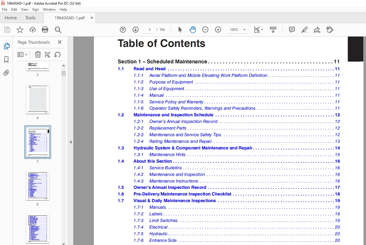
TABLE OF CONTENTS:
Skyjack SJIII 4740 DC Electric Scissors Service Manual 196430AD – PDF DOWNLOAD
Section 1 – Scheduled Maintenance 11
1 1 Read and Heed 11
1 1-1 Aerial Platform and Mobile Elevating Work Platform Definition 11
1 1-2 Purpose of Equipment 11
1 1-3 Use of Equipment 11
1 1-4 Manual 11
1 1-5 Service Policy and Warranty 11
1 1-6 Operator Safety Reminders, Warnings and Precautions 11
1 2 Maintenance and Inspection Schedule 12
1 2-1 Owner’s Annual Inspection Record 12
1 2-2 Replacement Parts 12
1 2-3 Maintenance and Service Safety Tips 12
1 2-4 Railing Maintenance and Repair 13
1 3 Hydraulic System & Component Maintenance and Repair 14
1 3-1 Maintenance Hints 15
1 4 About this Section 16
1 4-1 Service Bulletins 16
1 4-2 Maintenance and Inspection 16
1 4-3 Maintenance Instructions 16
1 5 Owner’s Annual Inspection Record 17
1 6 Pre-Delivery/Maintenance Inspection Checklist 18
1 7 Visual & Daily Maintenance Inspections 19
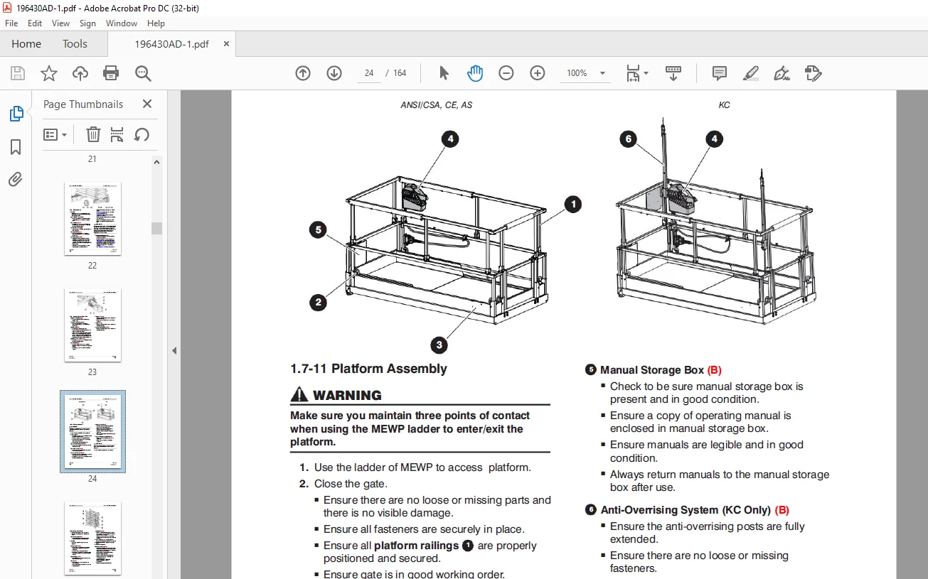
1 7-1 Manuals (B) 19
1 7-2 Labels (B) 19
1 7-3 Limit Switches 19
1 7-4 Electrical 20
1 7-5 Hydraulic 20
1 7-6 Entrance Side 20
1 7-7 Battery Tray Side 21
1 7-8 Extension Side 22
1 7-9 Hydraulic/Electric Tray Side 23
1 7-11 Platform Assembly 24
1 7-12 Lifting Mechanism 25
1 8 Function Tests 29
Section 2 – Maintenance Tables and Diagrams 31
2 1 Specifications & Features 32
2 2 Torque Specifications for Fasteners (US) 33
2 3 Torque Specifications for Fasteners (Metric) 34
2 4 Torque Specifications for Hydraulic Couplings & Hoses 35
2 5 Torque Specifications 36
2 6 Maximum Platform Capacities (Evenly Distributed) 37
2 7 Floor Loading Pressure 38
2 7-1 Locally Concentrated Pressure (LCP) 39
2 7-2 Overall Uniform Pressure (OUP) 39
Section 3 – System Component Identification and Schematics 41
3 1 Electrical Symbol Chart 42
3 2 Hydraulic Symbol Chart 43
3 3 Wire Number and Color Code 44
3 4 AC Cord Color Code 45
3 5 Hydraulic Parts List 46
3 6 Electrical Parts List 47
3 7 Drive, Brake Release and E-Lowering Manifold and Port Identification 50
3 8 Holding Valve and Port Identification 51
3 9 Platform Control Console 52
3 10 Base Control Console 53
3 11 Control Cable 54
3 12 High Speed Limit Switch Wiring 55
3 13 Anti-Overrising Limit Switch Wiring Diagrams 56
3 14 Hourmeter (CE) 57
3 15 Harness Wiring 58
3 16 Telematics Harness – ZTR 60
3 17 Main Manifold and Port Identidication 62
3 18 Hydraulic Schematics – ANSI/CSA, AS, KC 63
3 19 Hydraulic Schematics – CE & AS 64
3 20 Main Manifold Harness (ANSI/CSA) 65
3 21 Main Manifold Harness (CE, AS & KC) 66
3 22 Elevate Telematics Harness 67
3 23 Electrical Panel (ANSI/CSA) 68
3 24 Electrical Panel (ANSI/CSA) 69
3 25 Electrical Panel (CE) 70
3 26 Electrical Panel (CE) 71
3 27 Electrical Panel (AS) 72
3 28 Electrical Panel (AS) 73
3 29 Electrical Panel (KC) 74
3 30 Electrical Panel (KC) 75
3 31 Electrical Panel – Inverter Option 76
3 32 Telematics Wiring – Morey (ANSI/CSA) 77
3 33 Load Sensing and Beeper (CE & AS) 78
3 34 Horn/Tilt Switch/Flashing Light 79
3 35 Electrical Schematic – ANSI/CSA (All Options) 80
3 36 Electrical Schematics – ANSI/CSA (All Options) 81
3 37 Electrical Schematic – ANSI/CSA (No Options) 82
3 38 Electrical Schematic – ANSI/CSA (No Options) 83
3 39 Electrical Schematic (CE – All Options) 84
3 40 Electrical Schematic (CE – All Options) 85
3 41 Electrical Schematic (AS – All Options) 86
3 42 Electrical Schematic (AS – All Options) 87
3 43 Electrical Schematic (KC – All Options) 88
3 44 Electrical Schematic (KC – All Options) 89
Section 4 – Troubleshooting Information 91
4 1 Introduction 91
4 2 Electrical System – ANSI/CSA & KC 92
4 2-1 All Controls Inoperative 92
4 2-2 All Controls Except for Down Function Inoperative 93
4 2-3 All Controls Inoperative From Base Control Console 94
4 2-4 No Up Function from Base Control Console 94
4 2-5 Up Function Slow from Base Control Console 95
4 2-6 No Down Function from Base Control Console 95
4 2-7 All Controls Inoperative From Platform Control Console 96
4 2-8 No Up Function from Platform Controls 96
4 2-9 Up Function Slow from Platform Control Console 98
4 2-10 No Down Function from Platform Controls 98
4 2-11 No Emergency Down Function 98
4 2-12 Steer Only Inoperative 99
4 2-13 Right Steer Inoperative 99
4 2-14 Left Steer Inoperative 99
4 2-15 Drive Only Inoperative 100
4 2-16 No Drive or Steer when Platform Fully Lowered 100
4 2-17 No Drive or Steer when Platform Elevated 100
4 2-18 Platform Drives in Slow Speed Only 101
4 2-19 High/Low Torque Inoperative 101
4 2-20 Brake will not Release 101
4 2-21 Forward Drive Function Inoperative 102
4 2-22 Reverse Drive Function Inoperative 102
4 3 Electrical System – CE & AS 103
4 3-1 All Controls Inoperative 103
4 3-2 All Controls Except for Down Function Inoperative 104
4 3-3 All Controls Inoperative From Base Control Console 105
4 3-4 No Up Function from Base Control Console 105
4 3-5 Up Function Slow from Base Control Console 106
4 3-6 No Down Function from Base Control Console 106
4 3-7 All Controls Inoperative From Platform Control Console 107
4 3-8 No Up Function from Platform Controls 107
4 3-9 Up Function Slow from Platform Control Console 108
4 3-10 No Down Function from Platform Controls 108
4 3-11 No Emergency Down Function 109
4 3-12 Steer Only Inoperative 110
4 3-13 Right Steer Inoperative 110
4 3-14 Left Steer Inoperative 110
4 3-15 Drive Only Inoperative 111
4 3-16 No Drive or Steer when Platform Fully Lowered 111
4 3-17 No Drive or Steer when Platform Elevated 111
4 3-18 Platform Drives in Slow Speed Only 111
4 3-19 High/Low Torque Inoperative 112
4 3-20 Brake will not Release 112
4 3-21 Forward Drive Function Inoperative 113
4 3-22 Reverse Drive Function Inoperative 113
4 4 Hydraulic System – ANSI/CSA & KC 114
4 4-1 All Controls Inoperative 114
4 4-2 All System Sluggish 114
4 4-3 Platform Drifts Down 114
4 4-4 Platform Lifts Slowly 114
4 4-5 Platform Does Not Lift 114
4 4-6 Platform will not Lower 114
4 4-7 Platform Drives Slow 115
4 4-8 Platform will not Drive in Forward or Reverse 115
4 4-9 Brake(s) will not Release 115
4 4-10 MEWP will not Hold on a Grade 115
4 4-11 Platform does not Steer 115
4 4-12 High/Low Torque Inoperative 116
4 4-13 No Emergency Down Function 116
4 5 Hydraulic System – CE & AS 117
4 5-1 All Function Inoperative 117
4 5-2 All System Sluggish 117
4 5-3 Platform Drifts Down 117
4 5-4 Platform Lifts Slowly 117
4 5-5 Platform Does Not Lift 117
4 5-6 Platform will not Lower 117
4 5-7 Platform Drives Slow 118
4 5-8 Platform will not Drive in Forward or Reverse 118
4 5-9 Brake(s) will not Release 118
4 5-10 MEWP will not Hold on a Grade 118
4 5-11 Platform does not Steer 118
4 5-12 High/Low Torque Inoperative 119
4 5-13 No Emergency Down Function 119
Section 5 – Procedures 121
5 1 General 121
5 1-1 Safety and Workmanship 121
5 2 Platform 122
5 2-1 OEM Controller Electronics Information 122
5 2-2 OEM Controller Troubleshooting 123
5 2-3 OEM Controller Switch Wiring 124
5 2-4 Gate Spring Hinge Adjustment 125
5 3 Base 126
5 3-1 System Relief Pressure Adjustment 126
5 3-2 Lift Pressure Adjustment 126
5 3-3 Electronic Tilt Switch Setup Procedure 127
5 3-4 Pothole Limit Switches (LS4 & LS5) Replacement and Adjustment 130
5 3-5 Wheel Replacement and Torquing Procedure 131
5 3-6 Tightening and Torque Recommendations for Hydraulic Couplings and Hoses 134
5 3-7 Resistor – Voltage Divider 136
5 3-8 Counter Reset Procedure 137
5 3-9 Battery Maintenance 138
5 3-10 Charger Maintenance – Delta-Q 138
5 4 Scissors 146
5 4-1 High Speed Cutout Limit Switches (LS1A & LS1B) & Drive Override Limit Switch (LS6) Replacement and Adjustment 146
5 5 Load Sensing System 148
5 5-1 Systems Checks 148
5 5-2 GP-102 Control Module Pin Reference Chart 149
5 5-3 LED Error Codes – Quick Reference Chart 151
5 5-4 LED Error Codes – Code Breakdown Chart 152
5 5-5 Hand held Calibration/Diagnostic Tool Key Functions 154
5 5-6 Control Module Load Calibration – Code Messages & Definitions 155
5 5-7 Control Module Load Calibration Procedure 159
5 5-8 All Motion Alarm 162
5 5-9 Curve/Group Codes Chart 162
Need help? Contact: [email protected]
PLEASE NOTE:
- This is the SAME exact manual used by your dealers to fix your vehicle.
- The same can be yours in the next 2-3 mins as you will be directed to the download page immediately after paying for the manual.
- Any queries / doubts regarding your purchase, please feel free to contact [email protected]
S.M