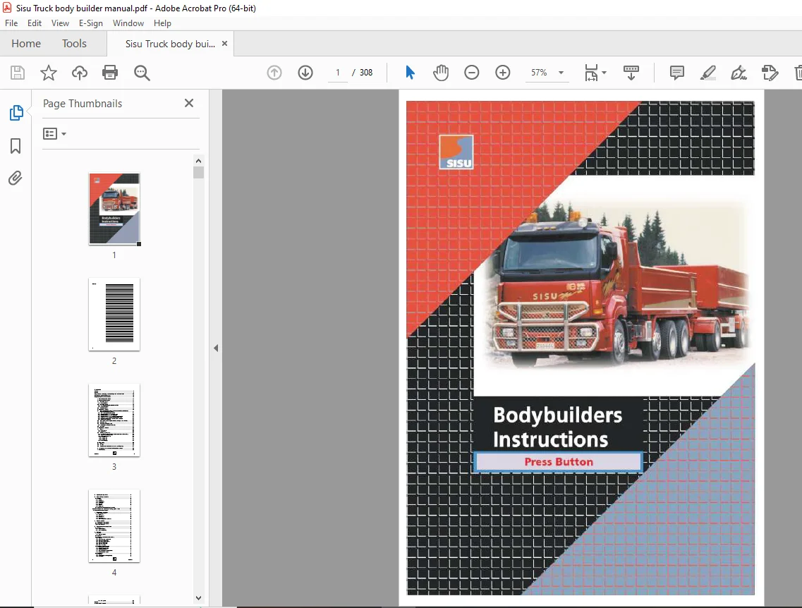
Sisu Truck Body Builders Instructions Manual – PDF DOWNLOAD
$28.95
Sisu Truck Body Builders Instructions Manual – PDF DOWNLOAD
Description
Sisu Truck Body Builders Instructions Manual – PDF DOWNLOAD
FILE DETAILS:
Sisu Truck Body Builders Instructions Manual – PDF DOWNLOAD
Language : English
Pages : 308
Downloadable : Yes
File Type : PDF
IMAGES PREVIEW OF THE MANUAL:
TABLE OF CONTENTS:
Sisu Truck Body Builders Instructions Manual – PDF DOWNLOAD
Contents
Cover1
Record
Regulations relating to the bodyworks of vehicles15
Machinery Directive (EC countries) 15
Regulations given by the authorities 15
1 Truck, bodywork, machine 17
2 Bodywork categorization 17
2 1 Bodyworks, group 1:17
2 1 1 Group 1 includes 17
2 2 Bodyworks, group 2 18
2 2 1 According to the Machinery Directive 98/37/EC 18
2 2 2 Group 2 bodyworks18
2 3 Vehicle/machinery19
3 Regulations, Group 1 20
3 1 Masses and main dimensions of vehicles and vehicle combinations in
international traffic (EC countries)21
3 1 1 Trailer axle weight table,EUcountries 22
3 1 2 Maximum laden masses of vehicles in theEU23
3 1 3 Maximum laden masses of trailers in theEU 23
3 1 4 Maximum laden masses of combination vehicles in theEU24
3 1 5 Vehicle, trailer and combination vehicle lengths in theEU 25
3 1 6 Maximum width and height of vehicles and trailers in theEU 25
3 1 7 Maneuverability in theEU25
3 2 Other regulations relating to the structures and operation of vehicles26
3 3 Brake adapting 26
3 4 Licenced mounting and repair 26
3 4 1 Licencing for modifications and repairs27
3 5 Bodyworks 27
4 Regulations, Group 2 28
4 1 General 28
4 1 1 Responsibility 28
4 1 2 Conformity28
4 2 Certifying the conformity 29
4 2 1 Procedure based on the declaration by the manufacturer of the machinery 30
4 2 2 ECtype-examination procedure30
4 2 3 Declaration of conformity 30
4 2 3 1 Declaration A31
4 2 3 2 Declaration B32
4 2 3 3 Declaration C32
4 2 4 Other certificates32
5 CEmarking33
5 1 General 33
5 2 CEmark 33
5 3 Examples of the declaration of conformity andCEmarking 34
6 Instructions, indications and technical documentation 38
7 Notified body 39
Contents 3
8 Acquiring the regulations 39
9 General safety instructions 41
9 1 Dangers 41
9 1 1 Falling42
9 1 2 Rolling over 42
9 1 3 Electric shock 42
9 1 4 Pneumatics 43
9 1 5 Hydraulics43
9 1 6 Coolant 43
9 1 7 Refrigerant 44
9 2 Unintentional starting/moving of the vehicle 44
General bodywork constructioning guidelines 45
Notes on bodywork construction: 46
1 Forces acting on vehicles47
1 1 Examining the forces 47
1 1 1 Static forces 47
1 1 2 Dynamic forces 47
1 1 3 Lateral forces 48
1 1 4 Torsional forces 48
1 1 5 Stress acting on the frame beams 48
2 Sisu frame beams 49
2 1 Sisu S-series framematerial 50
2 2 Sisu E-series framematerial 50
2 2 1 Heat treatment50
3 Strengthening the vehicle’s frame 50
3 1 General 50
3 1 1 Diagonal support50
3 1 2 Other strengthening 50
4 Subframe51
4 1 General 51
4 1 1 Subframe function 51
4 2 Material 51
4 3 Subframe construction and dimensioning 52
4 3 1 General 52
4 3 2 Subframe general requirements52
4 3 3 Subframe material section 53
4 3 4 Subframe bending resistance 54
4 3 5 Subframe plate bracings 55
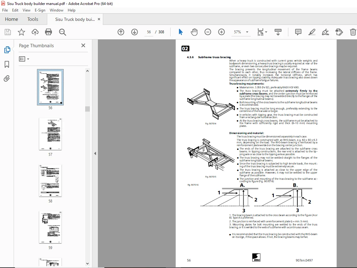
4 3 6 Subframe truss bracing56
4 3 7 Notes for mounting57
4 4 Subframemounting brackets58
4 4 1 Mounting bracket material 58
4 4 2 Flexible mounting brackets 58
4 4 3 Rigid mounting bracket58
4 4 4 Dimensioning the mounting brackets59
4 4 5 Mounting bracket location60
4 5 Bolted joints61
4 5 1 General 61
4 5 2 Bolted-joint dimensioning, tightening61
4 5 3 Frame holes 62
4 Contents
4 5 4 Drilling holes63
Record64
Flexible bodywork 65
1 Tipping platforms 67
1 1 General67
1 1 1 Tipping stability67
1 2 General construction principles68
1 2 1 Tipping support69
1 2 2 Tipping-gear mounting 69
1 2 3 Tipping stability test70
1 3 Construction 70
1 3 1 Hydraulics70
1 3 2 Tipping gear control device 70
1 3 3 Tipping cylinder/tipping gear 70
1 3 4 Mounting the tipping gear on a vehicle with a high frame 71
1 3 5 Warnings 71
1 3 6 Platform supports 72
1 3 7 Tipping-platform side guides 73
1 3 8 Tipping-platform service support73
1 4 Tipping-platform subframe 74
1 4 1 Subframe bending resistance 75
1 4 2 Truss bracing 76
1 4 3 Subframe mounting 76
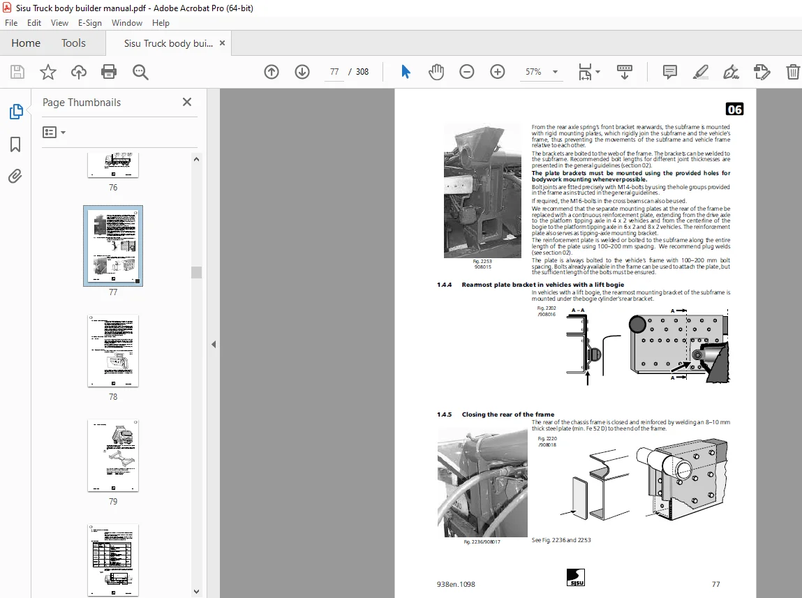
1 4 4 Rearmost plate bracket in vehicles with a lift bogie77
1 4 5 Closing the rear of the frame77
1 5 Chassis frame rear overhang78
1 6 Tipping platforms in trucks with high frames 78
1 6 1 General 78
1 6 2 Tipping-axle mounting 78
1 6 3 Frame truss bracing 79
2 Fixed platform or van body 80
2 1 General 80
2 2 Subframe80
2 3 Mounting the bodywork81
2 3 1 Mounting 81
2 3 2 Extremely rigid bodywork 82
3 Fixed platform + loader behind the cab 83
3 1 General 83
3 2 Mountings 83
3 2 1 Loader on the bodywork subframe 84
3 2 2 Loader on a separate subframe 84
3 2 3 Mounting with wear plates 84
3 2 4 Heavy-loader mounting84
4 Tail lifts85
4 1 General 85
4 2 Mounting 85
5 Timber truck 86
5 1 General 86
5 1 1 Log loader86
Contents 5
5 2 Vehicles with subframes (low-frame vehicles) 86
5 2 1 Subframe 86
5 3 Mounting the loader on a vehicle with a subframe88
5 4 Mounting the loader on a vehicle with a high frame 89
5 4 1 Sheath saddle mounting at the rear 89
5 5 Front grid90
5 6 Timber bunks 91
6 Tipping concrete tank 92
6 1 General 92
6 2 Subframe93
6 2 1 Mounting 93
7 Concrete mixer 94
7 1 General 94
7 2 Subframe94
7 2 1 Mounting 95
8 Interchangeable platform structures 96
8 1 General 96
8 2 Hoists 96
8 3 Interchangeable platform frame97
8 4 Interchangeable platform underframe97
8 5 Interchangeable platform subframe98
8 5 1 Subframe mounting 98
Rigid bodywork 99
1 Van body or container101
1 1 General structure information 101
1 2 Subframe 102
1 3 Mounting 103
1 3 1 Mounting the subframe or integrated mounting frame on the chassis frame 103
1 3 2 Mounting brackets 104
1 4 Freezing and refrigerating units 104
2 Rear loaders 105
3 Tank structures106
3 1 Chassis, tank structure and basic mounting guidelines 106
3 1 1 Chassis frame truss bracing 106
3 2 Tank mounting brackets 107
3 2 1 Mounting bracket mounting 108
3 3 Mounting the tank on the chassis frame109
3 4 Milk transport lorries 111
4 Bulk tanks 112
4 1 Mounting in general 112
4 2 Fixed bulk tank113
4 3 Tipping bulk tanks 114
4 3 1 Cradle mounting 115
5 Fire trucks116
6 Multi-wheel drive special vehicles117
6 Contents
Record 118
Other bodywork constructions119
1 Additional devices, mounting in front of the cab 121
1 1 General 121
1 2 Headgear 121
1 2 1 Mounting121
1 2 2 Headgear’s 3-point mounting attachment points: dimensioning 122
1 2 3 Additional devices attached to the headgear: operation 122
2 Additional devices/equipment, mounted on the cab or engine123
2 1 Roof-mounted additional equipment 123
2 2 Engine outlet ports for the cargo space auxiliary heating124
3 Additional Devices Mounted Behind the Cab 126
3 1 Refrigeration unit126
3 2 Hydraulics panel, hydraulic oil tank 126
3 3 Crane 128
3 3 1 General 128
3 3 1 1 Plan, check and calculate128
3 3 2 Roll axes128
3 3 2 1 Roll axes with one outrigger pair129
3 3 2 2 Roll axes with two outrigger pairs 130
3 3 3 Stability factor131
3 3 3 1 Calculating the stability factor 131
3 3 4 Axle loads and loading capacity 133
3 3 4 1 Selecting the bodywork length and location before weight calculation 136
3 3 5 Mounting the crane 137
3 3 5 1 Web mounting137
3 3 5 2 Shackle mounting 138
3 3 5 3 Reinforcing the mounting 139
3 3 5 4 Calculating the mounting 140
3 3 6 Subframe and wear plate 143
3 3 6 1 Subframe143
3 3 6 2 Short subframe 144
3 3 6 3 Wear plate 145
3 3 7 Crane mounting: up to 24 tonne meters 146
3 3 7 1 Standard 300mmframe, crane mounted on the wear plate146
3 3 7 2 Standard 300mmframe and standard subframe146
3 3 7 3 Standard 300mmframe, crane mounted on the short subframe 147
3 3 7 4 High C-frame, crane mounted on the wear plate 147
3 3 8 Crane mounting: 24–32 tonne meters148
3 3 8 1 Standard 300mmframe, subframe and reinforced mounting 148
3 3 8 2 460 mm-high C-frame148
3 3 9 Crane mounting: heavy cranes over 30 tonne meters149
3 3 9 1 Standard 300mmframe and subframe 149
3 3 9 2 High C-frame 150
3 3 9 3 400mmspecial frame for crane trucks with a driving front axle151
3 3 10 Crane commissioning inspection151
4 Additional devices, mounting between the axles 152
4 1 Heavy components attached to the frame 152
4 2 Belly blade 153
5 Additional devices, mounting between rear axles 154
Contents 7
5 1 Robson drive154
5 1 1 300mmchassis frame154
5 1 2 460mmchassis frame 155
6 Additional devices, mounting behind the rear axles 156
6 1 Tail lift 156
6 1 1 Mounting156
6 2 Rear-mounted cranes and loaders157
6 2 1 Roll axes: rear-mounted crane 158
6 2 2 Axle loads and loading capacity with a rear-mounted crane 159
6 2 2 1 Axle loads159
6 2 2 2 Subframe161
6 2 3 Crane mounting: rear mount, vehicle with subframe (300mmchassis frame) 162
6 2 3 1 Heavy cranes162
6 3 Crane mounting: rear mount, vehicle with high frame (460 mm)163
6 3 1 Sheath saddle mounting at the rear163
6 3 2 Heavy crane 163
6 4 Other devices installed behind the rear axle assembly 163
Record 164
PTOs (Power take-offs) 165
1 Engine PTOs165
1 1 REPTOengine PTOs165
1 1 1 CumminsM11 engines 166
1 1 2 Cummins N14 engines 167
1 2 Cogged-belt driven hydraulic pump 168
1 2 1 E11 vehicles 168
1 2 2 E14 vehicles 169
1 2 3 Cogged-belt driven hydraulic pump: mounting170
1 2 4 Requirements for mounting cogged-belt driven hydraulic pumps 172
2 Transmission PTOs173
2 1 PTOs for Eaton FullerRTO/RTLO transmissions 175
2 1 1 Transmission PTOs: below mount 175
2 1 2 Transmission PTOs: side mount 179
2 1 3 RTO14613 transmission PTOs: rear mount 180
2 2 PTOs for the EatonRTSO17316 transmission 182
2 3 PTOs for Renault B18 transmission 188
2 4 PTOs for ZF Ecosplit 16S221 transmission189
2 5 PTOs for AllisonHD4060P and 4560P transmissions 191
3 Calculating the output and selecting the hydraulic pump size 195
4 Propeller shafts 197
4 1 Propeller shaft operation 197
4 1 1 Joint angle compensation with universal joints198
4 1 1 1 Propeller shaft with two joints 199
5 Checking and adjusting the backslash of Chelsea PTOs 200
5 1 PTOwithout geared adapter 200
5 2 PTOwith geared adapter 201
Record 202
Towing vehicles, coupling devices 203
Coupling device directive 94/20/EC 206
8 Contents
Identifying approved and compatible coupling devices 206
ECapproval markings 206
Coupling inspection207
Coupling standards 207
Possible problems 208
National testing and approval of coupling devices208
Notes on various combinations! 209
1 Coupling devices211
1 1 Equations for coupling devices211
1 1 1 Dvalue211
1 1 2 Dvalue211
1 1 3 Dc value 211
1 1 4 V value 211
2 Trailer coupling mounting beam 212
2 1 Location of the mounting beam/trailer coupling 212
2 2 Mounting of Sisu end cross beam/mounting beam 212
2 2 1 Mounting213
2 2 1 1 To a standard frame 213
2 2 1 2 To a high frame214
2 2 2 Inspection 214
2 2 2 1 Mounting inspection 214
2 2 2 2 Maintenance inspections 214
2 3 Mounting of other manufacturer’s mounting beams (e g VBG) 215
2 4 Towing vehicle’s chassis frame and its possible strengthening 215
2 4 1 Low-frame vehicle215
2 4 2 High-frame vehicle 216
3 Trailer coupling 217
3 1 Trailer coupling position 217
3 2 Mounting of power actuator control valve 217
3 3 Other 217
3 4 Trailer couplings and equipment, supplied from the factory218
4 Fifth wheel219
4 1 Tractors for semi-trailers, general 219
4 2 Coupling dimensioning 219
4 2 1 Wheelbase219
4 2 2 Trailer’s front overhang 219
4 2 3 Coupling profile 220
4 2 4 Fifth wheel position 220
4 2 5 Fifth wheel characteristics221
4 2 6 Trailer’s inclination angles221
4 3 Mounting of fifth wheel 222
4 3 1 Fifth wheel height222
4 3 2 Fifth wheel’sDvalue, i e rated load223
4 3 3 Attaching of fifth wheel223
4 3 4 Fifth wheel to a high frame 224
4 4 Special fifth wheels 224
4 4 1 Switchable locking mechanism224
4 4 2 Sliding fifth wheel 224
4 4 3 Dual height fifth wheel224
Contents 9
4 5 Notes on mounting 224
4 6 Fifth wheels and equipment 225
5 Use, maintenance and service of coupling devices 226
5 1 Use of coupling device 226
5 1 1 Trailer coupling 226
5 1 2 Fifth wheels 226
5 2 Maintenance of coupling devices 226
Frame jobs 227
Chassis framemodifications 227
Damagerepair 228
Damage repair methods 228
Collision damage228
Frame job record228
1 Framematerials 229
229
2 Welding the frame 230
2 1 Foreword 230
2 1 1 Welding standards 230
2 2 Safety instructions 230
2 3 Protection 230
2 3 1 Disconnecting the electric system 231
2 3 2 Grounding the welding machine 231
2 3 3 Electronic control units and devices, Celect ECM, Mac ECU,ECASair suspension,
ABS braking system,HDtransmission 231
2 4 Preliminary work231
2 4 1 Cleaning231
2 4 2 Drying/heating 231
2 5 Filler metals 232
2 6 Opening fractures 232
2 7 Joint beveling and welding 233
2 7 1 Welding inner beams 234
2 7 2 Welding imperfections234
2 7 3 Filling holes 234
2 8 Weld joint post-treatment 234
2 8 1 Cooling 234
2 8 2 Grinding and cleaning234
2 8 3 Painting 234
3 Wheelbase alterations 235
3 1 General 235
3 2 Preliminary work235
3 3 Cutting the frame235
3 3 1 Cutting location236
3 3 2 Marking 236
3 3 3 Cutting angle237
3 3 4 Joining237
3 3 5 Welding the joint/joints238
3 3 6 Cross beams238
3 3 7 Inner frame joint locations238
3 4 Relocating the rear axle or bogie238
10 Contents
3 5 Propeller shafts 239
3 6 Adjusting the rear-axle angle and engine angle 240
3 7 Pneumatic pipes240
3 8 Electric wires240
3 9 Modification plate 241
3 10 Straightness of the frame 241
4 Installing an additional axle or removing an axle 241
4 1 General 241
4 2 Procedure 242
4 3 Marking 243
5 Mounting chassis frame cross beams 243
5 1 Removing cross beams243
5 2 Cross beam mounting 243
6 Extending the rear overhang 244
6 1 Rear corner lateral travel 244
6 2 Calculating the rear overhang length245
6 2 1 Rear axle assembly’s center of gravity 245
246
7 Documents247
8 Chassis frame damage repair/strengthening 247
8 1 General 247
8 2 Repair plates247
8 3 Stiffening the rear overhang for trailer towing 248
8 4 Flat steel bar stiffener for the S-series 249
Record250
Electric and pneumatic equipment251
1 Electric devices 251
1 1 Safety instructions 251
1 1 1 Preparing for electric work253
1 1 1 1 Temporary fuse for the ground wire 253
1 1 2 Electric welding 253
1 1 2 1 Disconnecting the electric system: 253
1 1 2 2 Grounding the welding machine253
1 1 2 3 Protection253
1 1 2 4 Electric control units and devices, Celect ECM, Mac ECU,ECASair suspension,
ABS braking system,HDtransmission253
1 1 3 Charging the batteries254
1 1 4 Oven drying 254
1 1 5 Alternator capacity/bodywork 254
1 2 Dimensioning fuses and wires256
1 2 1 General 256
1 2 2 Dimensioning the fuses 256
1 2 3 Dimensioning the wires 256
1 3 Connectors 257
1 4 Electrical center 257
1 5 Lead-through routing, connectors261
1 5 1 Wire lead-through routing from the cab to the chassis261
1 5 2 Connectors265
Contents 11
1 5 3 Electronic units 266
1 6 Power supply to bodywork or other additional installations 267
1 6 1 Antenna cables and power supply forCBandNMTphones and 267
1 6 1 1 CB/NMT/GSM267
1 6 1 2 NMT/GSM 267
1 6 1 3 267
1 6 2 Connecting side lights269
1 6 3 Rear-light connector lead-through hole in frame 269
1 6 4 Spare wires from cab to chassis 270
1 6 5 Trailer socket connections270
1 7 Electric connections in ADR-equipped vehicles271
1 7 1 General 271
1 7 2 Regulations 271
2 Pneumatic devices 272
2 1 Pneumatic system 272
2 1 1 General 272
2 1 2 Compressor 272
2 1 3 Air dryer 272
2 1 4 Warnings272
2 1 5 Device locations 273
2 2 Pressurizing and depressurizing the pneumatic system274
2 3 Bodywork pneumatic connections274
2 3 1 Compressed-air lead-through to cab 275
2 3 2 Connector parts 275
2 3 2 1 Cab bulkhead connector diagram 276
2 3 3 Fitting the pipe to the connector 277
Record 278
Lights and equipment, general279
1 Lamps and retro reflectors (EC regulations) 280
1 1 Following lamps and retro reflectors are mandatory on vehicles 280
1 2 In addition to above, following lamps and retro reflectors are optional 280
1 3 Installing and connecting of lamps281
1 4 Connections281
2 General requirements for lamps 282
2 1 Emarking on lamps282
2 1 1 E marking, front lamps283
2 1 2 E marking, rear lamps283
2 2 Reference values in use 283
2 3 Color of the light emitted forward/rearward 283
2 4 Visibility areas of lamps283
3 Lamps and retro reflectors for vehicles, front 284
3 1 Dipped-beam and main-beam headlamps (1), mandatory 284
3 1 1 Dipped-beam headlamps 284
3 1 2 Main-beam headlamps (1)285
3 2 Front position lamps (1), mandatory 285
3 3 Additional lamps on snow plowing vehicles (2), if required 285
3 4 Additional main-beam headlamps (3), optional 285
3 5 Front fog lamps (4), optional286
3 6 Direction indicator lamps (5), mandatory 286
12 Contents
3 6 1 Hazard warning signal, mandatory286
3 7 End-outline marker lamps (6), mandatory 286
3 8 Daytime running lamps (7), optional 287
3 9 Flashing hazard beacon (8), if required287
3 10 Lamp illuminating company’s name plate or route plate (9), optional 287
3 11 Front retro reflectors, optional287
4 Lamps and retro reflectors for vehicles, side 288
4 1 Side direction indicator lamps (1), mandatory 288
4 2 Side-marker lamps (2), mandatory288
4 3 Side retro reflectors (2), mandatory 288
5 Lamps and retro reflectors for vehicles, rear 289
5 1 Direction indicator lamp (1), mandatory289
5 2 Rear position lamp (2), mandatory289
5 3 Stop lamp (3), mandatory 289
5 4 Rear registration plate lamp (4), mandatory289
5 5 End-outline marker lamps (5), mandatory 290
5 6 Rear fog lamp (6), mandatory 290
5 7 Reversing lamp (7), mandatory 290
5 8 Rear retro reflectors (8), mandatory 290
5 9 Third stop lamp (9), optional 291
5 10 Work and additional lamps (10), optional 291
5 11 Retro-reflecting outline signals and commercial signals, optional291
5 12 Additional rear lamp set for tow trucks 291
5 13 Rear marking plates for heavy vehicles292
6 Lamps, retro reflectors and plates for trailers 293
6 1 Lamps and retro reflectors293
6 1 1 Direction indicator lamps (1), mandatory 294
6 1 2 Stop lamps (2), mandatory294
6 1 3 Rear registration plate lamp (3), mandatory294
6 1 4 Front position lamps, mandatory 294
6 1 5 Front retro reflectors, mandatory 294
6 1 6 Rear position lamps (4), mandatory294
6 1 7 Rear fog lamp (5), mandatory 294
6 1 8 End-outline marker lamps (6), mandatory 294
6 1 9 Side-marker lamps/retro reflectors, mandatory 294
6 1 10 Reversing lamp (7), mandatory294
6 1 11 Third stop lamp (8), optional 295
6 1 12 Work and additional lamps295
6 1 13 Rear retro reflectors (9), mandatory295
6 1 14 Retro reflectors for protruding structures 295
6 2 Plates296
6 2 1 Rear marking plates for long vehicles 296
6 2 2 Speed plate 296
7 Lamps and retro reflectors, approvals given by the authorities 297
7 1 Main-beam and dipped-beam headlamps 297
7 2 Direction indicator lamps 297
7 3 Stoplamps 297
7 4 Rear registration plate lamp297
Contents 13
7 5 Front and rear position lamps 297
7 6 Rear foglamp 297
7 7 Reversing lamp 297
7 8 End-outline marker lamps297
7 9 Lamps illuminating plates297
7 10 Flashing hazard beacon 297
7 11 Front fog lamps 298
7 12 Parking lamps 298
7 13 Daytime running lamps 298
7 14 Side-marker lamps 298
7 15 Lamps indicating towing vehicles 298
7 16 Retro reflectors 298
8 Markings on vehicles used for traffic subjected to license299
9 Other equipment300
9 1 Trailer socket connections 300
9 1 1 7-pole trailer socket 300
9 1 2 15-pole trailer socket ISO/DIS 12098300
9 1 3 VBG14-pole trailer socket301
9 1 4 VBG17-pole trailer socket 301
9 2 Tachograph 302
9 2 1 Inspections of tachograph 302
9 3 Rear-view mirrors 302
9 4 Visual obstructions 302
9 5 External projections 302
9 6 Antennas 302
9 7 Rear and lateral protection devices303
9 7 1 Rear underrun protection for motor vehicles and trailers 303
9 7 2 Requirements 303
9 8 Side guards for motor vehicles 304
9 8 1 Technical requirements for side guards 304
9 8 2 Forward edge of the side guard305
9 8 3 Rearward edge of the side guard 305
9 8 4 Lower edge of the side guard305
9 8 5 Upper edge of the side guard305
9 8 6 Derogations 305
9 8 7 Side guards for trailers306
9 9 Wheel guards and rain flaps 306
9 9 1 Wheel guards and rain flaps for trailers 307
9 10 Fuel tank308
9 10 1 Fuel tank on trailer308
9 11 Load lashing308
9 11 1 Lashing equipment 308
9 11 2 Winch 308
9 11 3 Lashing 308
9 11 4 Special provisions on lashing timber and containers 308
DESCRIPTION:
Sisu Truck Body Builders Instructions Manual – PDF DOWNLOAD
Foreword :
- A bodywork is always constructed for a truck due to its transportation or driving task. Sisu dealers will select the truck’s chassis in cooperation with the customer so that it will form, together with the bodywork, an optimal assembly for the vehicle’s transportation or driving task.
- The bodywork manufacturer/installer must always establish the vehicle’s intended purpose and operating conditions carefully with the vehicle owner.
- If the bodywork manufacturer/installer for some reason cannot follow this manual’s instructions relating to the chassis, or a procedure is not instructed in this manual, he must contact the nearest authorized SISU dealer/repair shop.
- The bodywork manufacturer/installer should agree with the other parties of the vehicle supply chain (dealer, importer, bodywork manufacturer/installer, etc.) on who will take full responsibility for the bodywork, issue the declaration of conformity, attach the CE mark, and provide and retain the required technical construction files for thirteen years, when the bodywork structure/structures are regarded as machinery.
- Mounting bodyworks on heavy trucks will inevitably lead to situations where there is a risk of accident. The risk is eliminated by planning and anticipating different stages of work.
- This section presents possible risks that must be anticipated for safe working.
G.B 24/02/25