

Piper PA-28-161 Cadet Parts Catalog Manual 761-828 – PDF DOWNLOAD
IMAGES PREVIEW OF THE MANUAL:
DESCRIPTION:
Piper PA-28-161 Cadet Parts Catalog Manual 761-828 – PDF DOWNLOAD
INTRODUCTION:
This illustrated Parts Catalog provides simple, positive identification of replacement parts for the Piper Model PA-28-161 Cadet,
manufactured by the Piper Aircraft Corporation of Vero Beach, Florida.
NOTE: DO NOT USE THIS CATALOG FOR RIGGING AND INSTALLATION PURPOSES.
1. The Catalog is divided into thirteen major sections as follows:
a. Section I to Xll inclusive contains all replacement parts for the complete airplane. Each section is subdivided and each division
includes an illustration and a parts listing.
b. Section Xlll is the Miscellaneous Group. This group includes an illustration and parts list for the Placards and Exterior Stencils
and a listing of the Optional Equipment Kits, Repair Kits and Special Tools.
2. The following is a brief explanation of the columns in the parts lists: (Refer to EXAMPLE below).
a. The FIGURE AND INDEX NUMBER column indicates the illustration figure number and its part index number. EXAMPLE;
2-1, the 2 is the figure number and the 1 is the index number. The figure number appears only at the top of each parts list
page.
b. The PART NUMBER column contains the identifying number of the replacement part and this number must be shown on all
parts orders.
c. The CODE column is for the purpose of indicating special uses of the part. An explanation of the letter code used is shown
on the grid (page) preceding each parts listing and pertains to that listing only.
d. The NOMENCLATURE column indicates the part name. This name must be shown on all parts orders.
e. The NO. REQ. (Number Required) column represents the total quantity of parts used per aircraft per figure when the part is
not indented and the quantity of parts used per assembly when the part is indented. The symbol AR listed in this column
means as required.
f. The SERIAL NUMBERS AFFECTED column indicates the part application by airplane serial number.
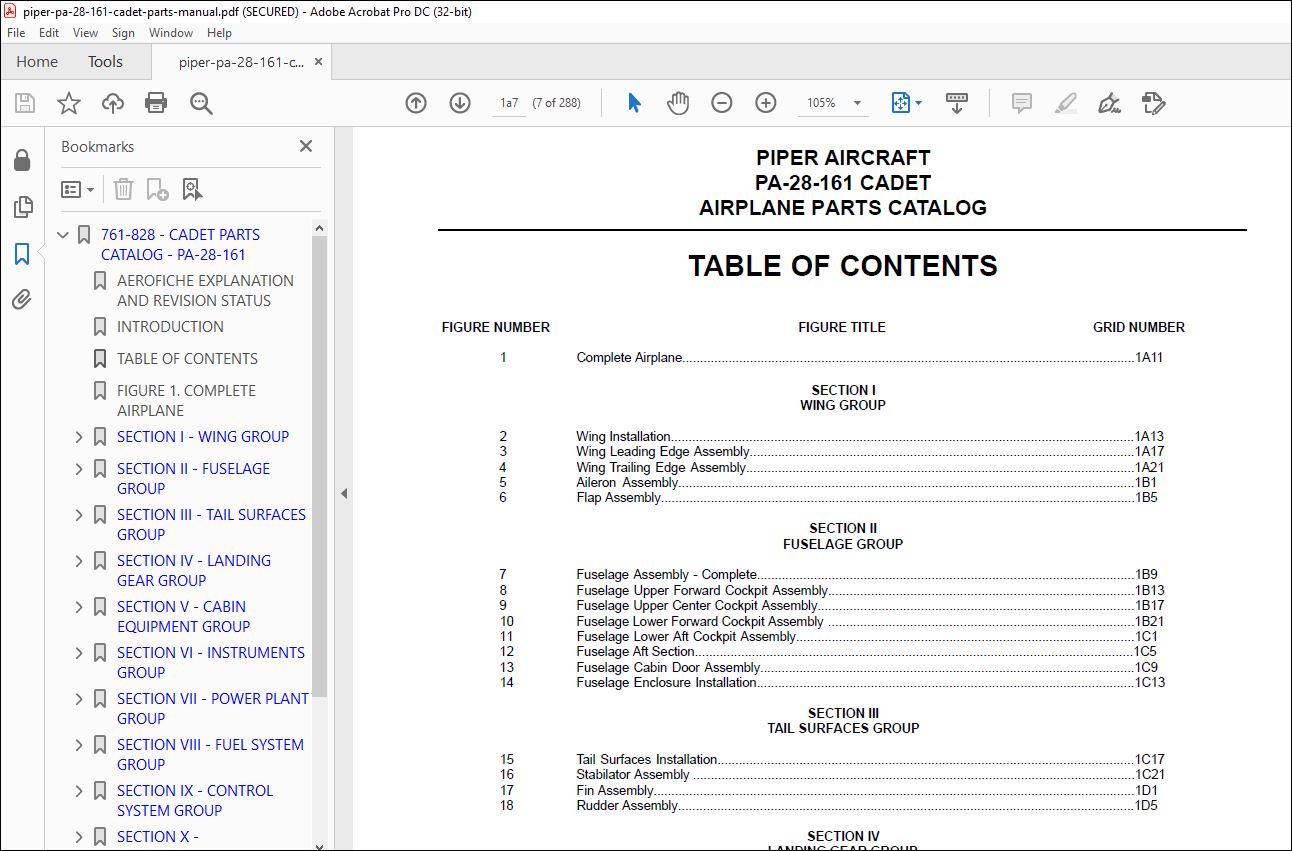
TABLE OF CONTENTS:
Piper PA-28-161 Cadet Parts Catalog Manual 761-828 – PDF DOWNLOAD
761-828 – CADET PARTS CATALOG – PA-28-161…………………………….. 1
AEROFICHE EXPLANATION AND REVISION STATUS…………………………. 2
INTRODUCTION…………………………………………………… 3
TABLE OF CONTENTS………………………………………………. 7
FIGURE 1. COMPLETE AIRPLANE……………………………………… 11
SECTION I – WING GROUP………………………………………….. 13
FIGURE 2. WING INSTALLATION………………………………….. 13
FIGURE 3. WING LEADING EDGE ASSEMBLY………………………….. 17
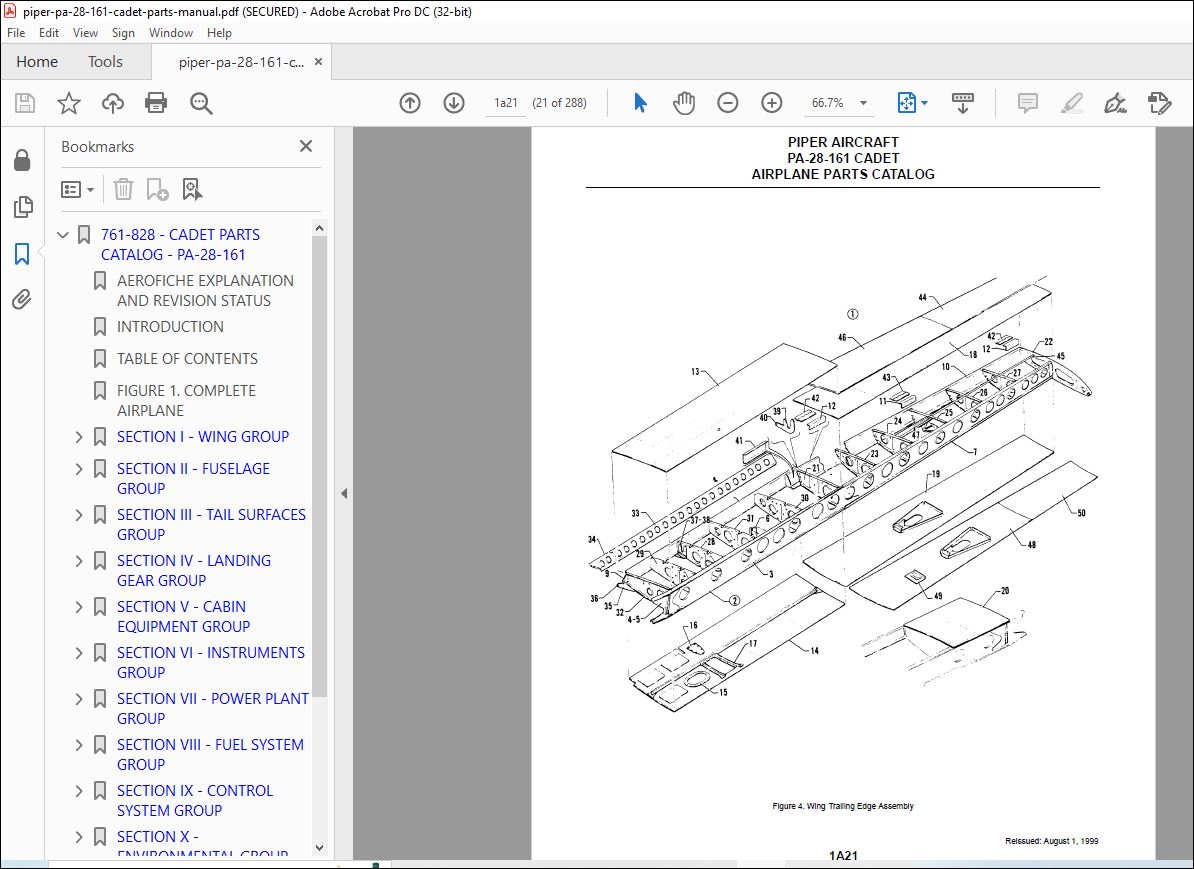
FIGURE 4. WING TRAILING EDGE ASSEMBLY…………………………. 21
FIGURE 5. AILERON ASSEMBLY…………………………………… 25
FIGURE 6. FLAP ASSEMBLY……………………………………… 29
SECTION II – FUSELAGE GROUP……………………………………… 33
FIGURE 7. FUSELAGE ASSEMBLY – COMPLETE………………………… 33
FIGURE 8. FUSELAGE UPPER FORWARD COCKPIT ASSEMBLY………………. 37
FIGURE 9. FUSELAGE UPPER CENTER COCKPIT ASSEMBLY……………….. 41
FIGURE 10. FUSELAGE LOWER FORWARD COCKPIT ASSEMBLY……………… 45
FIGURE 11. FUSELAGE LOWER AFT COCKPIT ASSEMBLY…………………. 49
FIGURE 12. FUSELAGE AFT SECTION………………………………. 53
FIGURE 13. FUSELAGE CABIN DOOR ASSEMBLY……………………….. 57
FIGURE 14. FUSELAGE ENCLOSURE INSTALLATION…………………….. 61
SECTION III – TAIL SURFACES GROUP………………………………… 65
FIGURE 15. TAIL SURFACES INSTALLATION…………………………. 65
FIGURE 16. STABILATOR ASSEMBLY……………………………….. 69
FIGURE 17. FIN ASSEMBLY……………………………………… 73
FIGURE 18. RUDDER ASSEMBLY…………………………………… 77
SECTION IV – LANDING GEAR GROUP………………………………….. 81
FIGURE 19. NOSE GEAR INSTALLATION…………………………….. 81
FIGURE 20. NOSE GEAR STRUT ASSEMBLY…………………………… 85
FIGURE 21. NOSE WHEEL ASSEMBLY (CLEVELAND)…………………….. 89
FIGURE 22. MAIN GEAR INSTALLATION…………………………….. 93
FIGURE 23. MAIN WHEEL ASSEMBLY……………………………….. 97
FIGURE 24. BRAKE ASSEMBLY…………………………………….101
FIGURE 25. MAIN AND NOSE LANDING GEAR STRUT FAIRING INSTALLATION….105
FIGURE 26. HAND BRAKE INSTALLATION…………………………….109
FIGURE 27. TOE BRAKE INSTALLATION……………………………..113
FIGURE 28. TOE BRAKE MASTER CYLINDER ASSEMBLY…………………..117
SECTION V – CABIN EQUIPMENT GROUP…………………………………121
FIGURE 29. COCKPIT FINISHING INSTALLATION………………………121
FIGURE 30. CARPET INSTALLATION………………………………..125
FIGURE 31. SEATS INSTALLATION…………………………………129
FIGURE 32. VERTICALLY ADJUSTABLE FRONT SEAT ASSEMBLY…………….133
SECTION VI – INSTRUMENTS GROUP……………………………………137
FIGURE 33. INSTRUMENTS INSTALLATION (TYPICAL)…………………..137
FIGURE 34. VACUUM SYSTEM INSTALLATION………………………….141
FIGURE 35. AUXILIARY VACUUM SYSTEM INSTALLATION…………………145
FIGURE 36. PITOT STATIC SYSTEM INSTALLATION…………………….149
SECTION VII – POWER PLANT GROUP…………………………………..153
FIGURE 37. POWER PLANT INSTALLATION……………………………153
FIGURE 38. ENGINE EXHAUST SYSTEM INSTALLATION…………………..157
FIGURE 39. ENGINE BAFFLE INSTALLATION………………………….161
FIGURE 40. OIL COOLER INSTALLATION…………………………….165
FIGURE 41. ENGINE COWL INSTALLATION……………………………169
FIGURE 42. ENGINE CONTROLS INSTALLATION………………………..173
SECTION VIII – FUEL SYSTEM GROUP………………………………….177
FIGURE 43. FORWARD FUEL SYSTEM INSTALLATION…………………….177
FIGURE 44. AFT FUEL SYSTEM INSTALLATION………………………..181
FIGURE 45. FUEL TANK ASSEMBLY…………………………………185
SECTION IX – CONTROL SYSTEM GROUP…………………………………189
FIGURE 46. CONTROL SYSTEM INSTALLATION…………………………189
FIGURE 47. FLAP CONTROL INSTALLATION…………………………..193
FIGURE 48. STABILATOR TRIM INSTALLATION………………………..197
FIGURE 49. RUDDER TRIM MECHANISM INSTALLATION…………………..201
FIGURE 50. CONTROL WHEEL INSTALLATION………………………….205
FIGURE 51. RUDDER PEDAL INSTALLATION…………………………..209
SECTION X – ENVIRONMENTAL GROUP…………………………………..213
FIGURE 52. CABIN HEAT AND DEFROSTER INSTALLATION………………..213
FIGURE 53. CABIN OVERHEAD AIR VENT INSTALLATION…………………217
SECTION XI – ELECTRICAL SYSTEM GROUP………………………………221
FIGURE 54. ELECTRICAL SYSTEM INSTALLATION………………………221
FIGURE 55. INSTRUMENT PANEL ELECTRICAL INSTALLATION……………..225
FIGURE 56. BATTERY BOX INSTALLATION……………………………229
FIGURE 57. EXTERNAL POWER SUPPLY INSTALLATION…………………..233
FIGURE 58. STROBE LIGHTS INSTALLATION………………………….237
SECTION XII – ELECTRONICS GROUP…………………………………..241
FIGURE 59. ELECTRIC TRIM INSTALLATION………………………….241
FIGURE 60. KING KAP 100/150 AUTOPILOT INSTALLATION………………245
FIGURE 61. EMERGENCY LOCATOR (ELT 110-4) INSTALLATION……………249
FIGURE 61A. PIPER AUTOMATIC LOCATOR (ELT 910) INSTALLATION……….252
FIGURE 62. ENCODER INSTALLATION……………………………….254
FIGURE 63. RADIO, ANTENNA SYSTEM, AND STATIC WICKS INSTALLATION…..257
FIGURE 64. AVIONICS COOLING INSTALLATION……………………….261
RADIO INSTALLATION DRAWINGS…………………………………..265
SECTION XIII – MISCELLANEOUS GROUP………………………………..267
FIGURE 65. PLACARDS AND EXTERIOR STENCILS………………………267
OPTIONAL EQUIPMENT KITS AND REPAIR KITS………………………..271
NUMERICAL INDEX…………………………………………………273
PLEASE NOTE:
- This is not a physical manual but a digital manual – meaning no physical copy will be couriered to you. The manual can be yours in the next 2 mins as once you make the payment, you will be directed to the download page IMMEDIATELY.
- This is the same manual used by the dealers inorder to diagnose your vehicle of its faults.
- Require some other service manual or have any queries: please WRITE to us at [email protected]
S.V


