Trusted Business
Verified & Licensed
Virus Free Files
100% Safe Downloads
Secure Payment
SSL Protected
Instant Delivery
Available Immediately
Nilfisk Advance CS7000 Service Manual – PDF DOWNLOAD
$29.95
Nilfisk Advance CS7000 Service Manual – PDF DOWNLOAD
Instant PDF Download
Available immediately
Save to Your Device
Download & keep forever
Antivirus Scanned
100% virus-free
Trusted Worldwide
175,000+ customers
Description
Nilfisk Advance CS7000 Service Manual – PDF DOWNLOAD
FILE DETAILS:
Nilfisk Advance CS7000 Service Manual – PDF DOWNLOAD
Language : English
Pages : 464
Downloadable : Yes
File Type : PDF
IMAGES PREVIEW OF THE MANUAL:
TABLE OF CONTENTS:
Nilfisk Advance CS7000 Service Manual – PDF DOWNLOAD
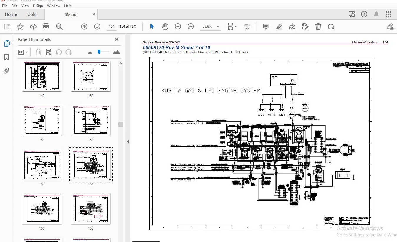
General Information........................................................................................... 13
	General Machine Description............................................................................... 13
	Service Manual Purpose and Application.................................................................... 13
	Revision History.......................................................................................... 13
	Other Reference Manuals and Information Sources........................................................... 14
		Nilfisk-Advance Publications.......................................................................... 14
	Conventions............................................................................................... 15
	Parts and Service......................................................................................... 15
	Nameplate................................................................................................. 15
	Cautions and Warning Symbols.............................................................................. 16
	General Safety Instructions............................................................................... 16
	Hopper Prop Rod........................................................................................... 18
		To Engage the Hopper Prop Rod......................................................................... 18
			To Disengage the Hopper Prop Rod.................................................................. 18
	Jacking the Machine....................................................................................... 19
	Transporting the Machine.................................................................................. 19
	Towing the Machine........................................................................................ 20
	Diagnostic and Service Tools.............................................................................. 21
	Technical Specifications.................................................................................. 22
		General Specifications................................................................................ 22
		Fastener Torque Specifications........................................................................ 25
		Overall Dimensions.................................................................................... 26
	Maintenance............................................................................................... 27
		Maintenance Schedule.................................................................................. 27
		Recommended Service Materials......................................................................... 27
		Daily Maintenance..................................................................................... 27
		Maintenance Every 15 to 20 Hours...................................................................... 28
		Monthly Maintenance................................................................................... 28
		Maintenance Every 150 Hours........................................................................... 28
		Maintenance Every 400 Hours........................................................................... 28
		Maintenance Every 800 to 1000 Hours................................................................... 29
		Maintenance Every 1500 Hours.......................................................................... 29
		Maintenance Every 1900 Hours.......................................................................... 29
		Maintenance Every 2000 Hours.......................................................................... 29
		Lubrication Points.................................................................................... 30
		EcoFlex System Maintenance............................................................................ 31
			To Purge When Changing Detergents (the scrub system must be off).................................. 31
			To Purge Weekly (the scrub system must be off).................................................... 31
			To Change the Detergent Mix Ratio (the scrub system must be on)................................... 32
	PM Checklist.............................................................................................. 33
	Machine Controls.......................................................................................... 35
		Control Panel - General Layout........................................................................ 35
		Miscellaneous Controls................................................................................ 35
		Miscellaneous Indicators.............................................................................. 36
		Scrub Controls........................................................................................ 37
		Scrub Indicators...................................................................................... 38
		Sweep Controls........................................................................................ 38
		Sweep Indicators...................................................................................... 39
		Hopper Controls ...................................................................................... 40
	LCD Displays.............................................................................................. 40
		General Displays...................................................................................... 40
			Battery Machine................................................................................... 40
			LPG Machine....................................................................................... 40
			Diesel Machine.................................................................................... 41
			Broom Adjustment (Battery, LPG and Diesel)........................................................ 41
			Battery Charge Indicator.......................................................................... 41
		Fault, Caution and Warning Displays................................................................... 42
			Fault Displays.................................................................................... 42
			Caution Displays.................................................................................. 42
			Warning Displays.................................................................................. 43
	Steering Wheel............................................................................................ 44
	Foot Pedals............................................................................................... 44
Chassis System................................................................................................ 45
	Component Locations - Battery Machine (major components).................................................. 45
	Component Locations - LPG and Diesel Machine (major components)........................................... 46
Control System................................................................................................ 47
	Functional Description.................................................................................... 47
	CAN Bus Circuit........................................................................................... 48
		CAN BUS message routing............................................................................... 49
			Control Panel..................................................................................... 49
			Main Machine Controller........................................................................... 49
			Drive Controller.................................................................................. 49
			Steering Controller............................................................................... 50
	Component Locations....................................................................................... 51
	Troubleshooting........................................................................................... 52
		Fault Codes........................................................................................... 52
		Hidden Menus.......................................................................................... 57
			Configuration Display............................................................................. 57
			Configuration Menu................................................................................ 59
			User Options Menu................................................................................. 63
	Service Mode.............................................................................................. 68
		To Operate:........................................................................................... 71
		Control Panel LEDs all stay lit - CAN Bus problems.................................................... 75
	Removal and Installation.................................................................................. 76
		Main Machine Controller .............................................................................. 76
		Control Panel......................................................................................... 77
	Specifications............................................................................................ 78
		Shop Measurements – Main Machine Controller........................................................... 78
			J2 Connector (White).............................................................................. 78
			J3 Connector (Gray)............................................................................... 79
			J7 Connector (Black).............................................................................. 81
Dust Control/DustGuard™ Systems............................................................................... 83
	Functional Description ................................................................................... 83
		Overview.............................................................................................. 83
			Dust Control System............................................................................... 83
			DustGuard™ Spray System (optional)................................................................ 84
		DustGuard™ System Wiring Diagram...................................................................... 85
		Circuit Description................................................................................... 86
	Component Locations....................................................................................... 87
		Impeller and Filter System............................................................................ 87
			Dust Control Filter Switch ....................................................................... 88
			DustGuard™ Spray System........................................................................... 89
	Maintenance and Adjustments .............................................................................. 90
		To Clean the Dust Control Filter...................................................................... 90
			To Remove the Dust Control Filter................................................................. 90
			To Clean the Dust Control Filter.................................................................. 91
			To Reinstall the Dust Control Filter.............................................................. 91
		To Clean the DustGuard™ Strainer Screen............................................................... 92
		To Clean the DustGuard™ Spray Nozzles................................................................. 93
		To Adjust the DustGuard™ Spray Nozzles................................................................ 93
	Troubleshooting........................................................................................... 94
	Removal and Installation ................................................................................. 96
		To Remove and Reinstall the DustGuard™ Solenoid Valve Assembly........................................ 96
		To Remove and Reinstall the DustGuard™ Pump........................................................... 97
		To Remove and Reinstall the Dust Control Filter Switch................................................ 98
		To Remove and Reinstall the Impeller Assembly......................................................... 98
		To Disassemble and Reassemble the Impeller Assembly................................................... 99
	Specifications............................................................................................100
Electrical System.............................................................................................101
	Functional Description....................................................................................101
		Overview..............................................................................................101
		Wiring Harnesses......................................................................................104
		Circuit Protection....................................................................................105
		Current Sensors.......................................................................................105
		42 Volt Alternator (Generator)........................................................................105
		Lighting..............................................................................................105
		Low Voltage Cutout....................................................................................106
		42 Volt Generator.....................................................................................106
		Headlights............................................................................................107
			Incandescent Headlights...........................................................................107
			LED Headlights....................................................................................107
	Component Locations.......................................................................................108
	Electrical Panel Contactor/Relay location.................................................................110
	Harness to Harness Connector Locations....................................................................111
	Connector Pin-Outs........................................................................................112
		Component ID to Connector ID Look Up Table............................................................112
	Wiring Connections........................................................................................134
		K14 Safety Relay and K15 Auxiliary Relays.............................................................134
			Early Style K14 Safety Relay......................................................................134
			Early Style K15 Auxiliary Relay...................................................................134
			 Late style K14 Safety Relay and K15 Auxiliary Relay..............................................135
	Maintenance and Adjustments...............................................................................136
		Charging the Battery (Battery Model)..................................................................136
		Generator Drive Belt..................................................................................136
	Troubleshooting...........................................................................................136
		42 volt generator is not charging.....................................................................136
		Insufficient machine operation time (Battery Model)...................................................136
		Insufficient machine operation time with engine off (Hybrid models)...................................136
	Removal and Installation..................................................................................137
		42 volt Generator Drive Belt..........................................................................137
		42 volt Generator ....................................................................................139
		Generator Drive Belt Tensioner........................................................................139
		Head Light bulb - Standard 12v Halogen................................................................140
	Specifications............................................................................................141
		Battery (Battery Model)...............................................................................141
		Low Voltage Cut Out...................................................................................141
		Battery Run Time (Battery powered machine)............................................................141
		Current Sensors.......................................................................................142
	Wiring Diagrams...........................................................................................146
	Working with Schematics and Diagrams......................................................................146
		Navigation............................................................................................146
			Common Schematic Symbols..........................................................................147
	56509170 Rev M Sheet 1 of 10..............................................................................148
	56509170 Rev M Sheet 2 of 10..............................................................................149
	56509170 Rev M Sheet 3 of 10..............................................................................150
	56509170 Rev M Sheet 4 of 10..............................................................................151
	56509170 Rev M Sheet 5 of 10..............................................................................152
	56509170 Rev M Sheet 6 of 10 .............................................................................153
	56509170 Rev M Sheet 7 of 10 .............................................................................154
	56509170 Rev M Sheet 8 of 10 .............................................................................155
	56509170 Rev M Sheet 9 of 10 .............................................................................156
	56509170 Rev M Sheet 10 of 10.............................................................................157
	TrackClean Wiring with Access Control.....................................................................158
	TrackClean Wiring without Access Control..................................................................159
	LEV Engine Side Wiring 56511576_REV_A_LEV_ENG sheet 1 of 1................................................160
Engine System - LPG...........................................................................................161
	Functional Description....................................................................................161
		Circuit Descriptions..................................................................................162
			Ignition System...................................................................................162
			Engine Starter Control............................................................................164
		Throttle Control Modes................................................................................165
			Ignition Off......................................................................................165
			Ignition On.......................................................................................166
			Cranking..........................................................................................167
			Normal Running....................................................................................168
			Engine RPM Control................................................................................168
		Normal Engine Shut Off................................................................................169
			Step One..........................................................................................169
			Step Two..........................................................................................170
			Engine Overheat Shutdown..........................................................................171
			Lost Oil Pressure Shutdown........................................................................172
	Component Locations.......................................................................................173
	Maintenance and Adjustments...............................................................................177
		Maintenance Checklist.................................................................................177
		Change Engine Oil and Oil Filter......................................................................178
		Change Engine Coolant.................................................................................179
		Inspect Air Filter....................................................................................179
		Replace Air Filters...................................................................................179
	Troubleshooting...........................................................................................180
		Checking Spark........................................................................................180
		Checking LPG Primary Pressure.........................................................................180
		No crank - The starter does not engage................................................................181
		Cranks but does not start – No Spark..................................................................182
		Cranks but does not start (has sufficient spark)......................................................182
		Achieves one but not ALL RPM modes....................................................................183
	Removal and Installation..................................................................................184
		Engine RPM Sensor Installation........................................................................184
		Engine Assembly.......................................................................................184
	Specifications............................................................................................185
		Fuel System...........................................................................................185
		Engine OIl............................................................................................185
		Engine Coolant........................................................................................185
		Shop Measurements ....................................................................................185
			Ignition System...................................................................................185
			Spark Controller Measurements:....................................................................186
			Governor Control System ..........................................................................186
			Woodward L Series Actuator Measurements...........................................................186
			Fuel System.......................................................................................187
			Engine ...........................................................................................187
	Special Tools.............................................................................................188
Engine System - LPG LEV.......................................................................................189
	Functional Description....................................................................................189
		Circuit Descriptions..................................................................................190
			Engine Starter Control............................................................................190
			Engine RPM Control................................................................................191
		Normal Engine Shut Off................................................................................191
		Engine Protection Modes...............................................................................191
	Component Locations.......................................................................................192
	Maintenance and Adjustments...............................................................................194
		Maintenance Checklist.................................................................................194
		Change Engine Oil and Oil Filter......................................................................194
		Change Engine Coolant.................................................................................194
		Inspect Air Filter....................................................................................195
		Replace Air Filters...................................................................................195
	Troubleshooting...........................................................................................196
	Engine Management System..................................................................................196
		Checking Spark........................................................................................196
		Checking LPG Primary Pressure.........................................................................197
	Removal and Installation..................................................................................198
		Engine Assembly.......................................................................................198
	Specifications............................................................................................199
		Fuel System...........................................................................................199
		Engine Oil............................................................................................199
		Engine Coolant........................................................................................199
		Shop Measurements ....................................................................................199
			Ignition System...................................................................................199
			Fuel System.......................................................................................200
			Engine ...........................................................................................200
	Special Tools.............................................................................................201
Engine System - Petrol (Gasoline).............................................................................203
	Functional Description....................................................................................203
		Kubota WG972-GL-E3-NFK-1 Petrol (Gasoline)............................................................203
		Circuit Descriptions..................................................................................204
			Ignition System...................................................................................204
			Engine Starter and Carburetor Choke Control.......................................................206
		Throttle Control Modes................................................................................207
			Ignition Off......................................................................................207
			Ignition On.......................................................................................208
			Cranking..........................................................................................209
			Normal Running....................................................................................210
			Engine RPM Control................................................................................210
		Normal Engine Shut Off................................................................................211
			Engine Overheat Shutdown..........................................................................212
			Lost Oil Pressure Shutdown........................................................................213
	Component Locations.......................................................................................214
		Engine Right Side View (Toward front of machine)......................................................215
		Engine Back Side View (Toward right of machine).......................................................216
		Engine Left Side View (Toward back of machine)........................................................216
		Fuel Tank Area........................................................................................217
	Maintenance and Adjustments...............................................................................218
		Maintenance Checklist.................................................................................218
		Change Engine Oil and Oil Filter......................................................................219
		Change Engine Coolant.................................................................................219
		Inspect Air Filter....................................................................................220
		Replace Air Filters...................................................................................220
	Troubleshooting...........................................................................................221
		Checking Spark........................................................................................221
		No crank - The starter does not engage................................................................221
		Cranks but does not start – No Spark..................................................................222
		Cranks but does not start (has sufficient spark)......................................................222
		Achieves one but not ALL RPM modes....................................................................223
	Removal and Installation..................................................................................224
		Engine RPM Sensor Installation........................................................................224
		Engine Assembly.......................................................................................224
	Specifications............................................................................................225
		Engine Oil............................................................................................225
		Engine Coolant........................................................................................225
		Shop Measurements ....................................................................................225
			Ignition System...................................................................................225
			Spark Controller Measurements:....................................................................226
			Governor Control System ..........................................................................226
			Woodward L Series Actuator Measurements...........................................................226
			Fuel System.......................................................................................227
			Engine ...........................................................................................227
	Special Tools.............................................................................................228
Engine System, Diesel ........................................................................................229
	Functional Description....................................................................................229
		Engine starter control................................................................................229
		Fuel pump control.....................................................................................230
		Engine Protection.....................................................................................231
			Over Temperature Shutdown.........................................................................232
			Low Oil Pressure Shutdown.........................................................................233
		Engine RPM control....................................................................................234
		Glow plug control.....................................................................................236
	Component Locations.......................................................................................237
	Maintenance and Adjustments...............................................................................240
		Diesel Engine Maintenance Schedule....................................................................240
		Change Engine Oil and Oil Filter......................................................................241
		Change Engine Coolant.................................................................................241
		Replace Fuel Filter...................................................................................241
		Bleed Fuel System.....................................................................................242
		Inspect Air Filter....................................................................................242
		Replace Air Filters...................................................................................243
	Troubleshooting...........................................................................................244
		No crank – The starter does not engage................................................................244
		Cranks but does not start.............................................................................244
		Cannot Achieve Either Run or Maximum Engine Speed Settings (Run 2200 RPM, Maximum Power 2400 RPM).....246
		Compression Test......................................................................................247
	Removal and Installation..................................................................................249
		Engine RPM Sensor Installation........................................................................249
		Engine Assembly.......................................................................................249
	Specifications............................................................................................250
		Fuel Pump; ...........................................................................................250
		Glow Plugs............................................................................................250
		Engine Compression....................................................................................250
		Engine Oil Capacity...................................................................................250
		Engine Oil Type.......................................................................................250
		Engine Oil Viscosity..................................................................................251
		Cooling System........................................................................................251
			Engine Coolant....................................................................................251
			Radiator Cap......................................................................................251
		Shop Measurements ....................................................................................251
			Engine RPM Sensor.................................................................................251
			Actuator..........................................................................................251
			Engine Compression................................................................................252
			Fuel System Return Fuel Flow......................................................................252
			Starter...........................................................................................252
			Glow Plug Relay ..................................................................................252
	Special Tools.............................................................................................253
Hopper System.................................................................................................254
	Functional Description ...................................................................................254
		Overview..............................................................................................254
		Hopper System Wiring Diagram..........................................................................255
		Hopper Hydraulic System Circuit Details...............................................................256
			Hopper at Rest....................................................................................256
			Hopper Being Raised...............................................................................256
			Hopper Being Lowered..............................................................................257
		Circuit Description...................................................................................257
	Component Locations ......................................................................................258
		Upper and Lower Hopper................................................................................258
		Hydraulic Power Pack Assembly.........................................................................259
		Hopper Dump Door......................................................................................260
		Hopper Dump Door Actuator.............................................................................260
		Dump Door Extend and Retract Limit Switches...........................................................260
		Hopper Interlock Switch...............................................................................261
		Hopper Prop Rod and Pull Rod..........................................................................261
	Troubleshooting...........................................................................................262
	Removal and Installation .................................................................................264
		To Remove and Reinstall the Hydraulic Power Pack Assembly.............................................264
			LPG and Diesel Models.............................................................................264
			Battery Models....................................................................................266
		To Remove and Reinstall the Hopper Lift Cylinder......................................................268
		To Replace the Oil in the Hydraulic System............................................................271
		To Remove and Reinstall the Hopper Dump Door Actuator Assembly........................................280
		Hopper Interlock Switch Replacement...................................................................280
	Specifications............................................................................................281
Options and Accessories.......................................................................................282
Recovery System...............................................................................................292
	Functional Description ...................................................................................292
		Overview..............................................................................................292
		Recovery System Wiring Diagram........................................................................293
		Circuit Description...................................................................................294
	Component Locations ......................................................................................295
		Recovery Tank.........................................................................................295
		Recovery Tank Cover and Debris Basket.................................................................295
		Vacuum Fan Cover Assembly.............................................................................296
		Vacuum Motors.........................................................................................296
		Float Cage and Ball Assemblies........................................................................296
	Maintenance and Adjustments ..............................................................................297
		To Clean the Vacuum Filter and Filter Screen..........................................................297
		To Clean the Debris Basket............................................................................298
	Troubleshooting...........................................................................................299
	Removal and Installation .................................................................................300
		To Remove the Recovery Tank...........................................................................300
		To Reinstall the Recovery Tank........................................................................302
		To Remove and Reinstall a Vacuum Motor................................................................303
	Specifications............................................................................................304
	Special Tools.............................................................................................304
Scrub System..................................................................................................305
	Functional Description....................................................................................305
		Overview..............................................................................................305
		Scrub Pressure Control................................................................................305
		Scrub System Wiring Diagram...........................................................................306
		Circuit Description...................................................................................307
			The Following Conditions Must be Met for the Scrub System To Operate..............................307
			Scrub Deck Actuator Motor.........................................................................307
			Brush Current Sensor..............................................................................308
	Component Locations.......................................................................................308
		Scrub Motor Assemblies................................................................................308
		Right Scrub Arm Gas Spring and Lever Arm Bracket......................................................308
		Side Squeegee Assemblies..............................................................................309
		Scrub Deck Actuator...................................................................................309
	Maintenance and Adjustments...............................................................................310
		To Replace a Leading Deck Blade.......................................................................310
		To Replace a Trailing Deck Blade......................................................................310
	Troubleshooting...........................................................................................311
	Removal and Installation..................................................................................312
		To Remove and Reinstall a Side Squeegee Assembly......................................................312
		To Remove and Reinstall the Scrub Deck Actuator.......................................................313
		To Remove and Reinstall the Scrub Deck................................................................313
		To Remove and Reinstall a Scrub Motor Assembly........................................................316
		To Replace the Scrub Motor Carbon Brushes.............................................................317
	Specifications............................................................................................320
	Special Tools.............................................................................................321
Solution System...............................................................................................322
	Functional Description....................................................................................322
		Overview..............................................................................................322
		Solution Flow Control - Non-EcoFlex™ Machines.........................................................322
		Solution Flow Control - EcoFlex™ Machines.............................................................322
		EcoFlex™ Detergent System.............................................................................323
		Extended Scrub System.................................................................................323
		Optional Hot Water System (LP and Diesel EcoFlex™ Machines Only)......................................323
		Optional Wash Hose Kit................................................................................323
		Optional High-pressure Spray System (LP and Diesel Only)..............................................324
		Solution Level Sensor.................................................................................324
		Solution System Wiring Diagram........................................................................325
		Circuit Description...................................................................................326
	Component Locations.......................................................................................329
		Solution Tank.........................................................................................329
			Drain Hose........................................................................................329
			Solution Filter and Solution Shutoff Valve........................................................329
			Solution Pressure Sensor..........................................................................330
		Solution Pump (EcoFlex™ Models Only)..................................................................330
		Low Pressure (Wash Hose) Pump ........................................................................330
		Solution Solenoid Valve...............................................................................331
		Solution Nozzles......................................................................................331
		EcoFlex™ Detergent Bottles and Pumps..................................................................332
		High-pressure Spray System Pump.......................................................................332
		Extended Scrub System.................................................................................333
	Maintenance and Adjustments...............................................................................334
		To Clean the Solution Filter Screen...................................................................334
		To Clean the Extended Scrub System Strainer...........................................................335
		To Clean the High Pressure Solution Filter............................................................335
		To Adjust the Belt Tension on the High Pressure Pump..................................................336
	Troubleshooting...........................................................................................337
	Removal and Installation..................................................................................340
		To Remove and Reinstall the Solution Tank.............................................................340
		To Remove and Reinstall the Solution Shutoff Valve....................................................344
		To Remove and Reinstall the Solution Filter Assembly..................................................344
		To Remove and Reinstall the Solution Solenoid Valve...................................................345
		To Remove and Reinstall a Detergent Pump (EcoFlex™ Models Only).......................................345
	Specifications............................................................................................346
	Special Tools.............................................................................................348
Squeegee System...............................................................................................349
	Functional Description....................................................................................349
		Overview..............................................................................................349
		Squeegee System Wiring Diagram........................................................................349
		Circuit Description...................................................................................350
	Component Locations.......................................................................................350
	Maintenance and Adjustments...............................................................................351
		To Remove and Reinstall the Squeegee Blades...........................................................351
			To Remove and Reinstall the Front Squeegee Blade..................................................351
			To Remove and Reinstall the Rear Squeegee Blade...................................................352
		Squeegee End Wheels...................................................................................352
		Squeegee Caster Wheel Bearings........................................................................352
		To Adjust the Squeegee Tilt...........................................................................353
		To Adjust the Squeegee Casters........................................................................354
	Troubleshooting...........................................................................................355
	Removal and Installation..................................................................................356
		To Remove and Reinstall the Squeegee Support Assembly.................................................356
		To Remove and Reinstall the Squeegee Lift Arm.........................................................356
		To Remove and Reinstall the Squeegee Lift Actuator....................................................357
	Specifications............................................................................................358
	Special Tools.............................................................................................358
Steering System...............................................................................................359
	Functional Description....................................................................................359
		Summary...............................................................................................359
			Steering Wheel Rotation Sensor....................................................................359
			Steering Actuator.................................................................................360
			Steering Travel Limit Switches....................................................................361
		Steering Controller...................................................................................361
		Steering System Wiring Diagram........................................................................362
		Circuit Description...................................................................................363
	Component Locations.......................................................................................367
	Maintenance and Adjustments...............................................................................368
	Troubleshooting...........................................................................................368
		Diagnostic Trouble Codes (DTCs).......................................................................368
			To retrieve steering system codes from the “hidden menu”:.........................................368
		Diagnostic Trouble Code Table.........................................................................369
		Symptom Troubleshooting (No DTC stored)...............................................................373
			Steering Inoperative  - Steering Controller Status LED is Blinking Rapidly........................373
			Steering Inoperative  - Steering Controller Status LED is Off.....................................373
			Steering Inoperative  - Steering Controller Status LED is On Steady...............................373
			No “Steering Feel”................................................................................373
			Steering Wheel Is Difficult To Turn...............................................................373
	Removal and Installation..................................................................................374
		Steering Wheel Assembly...............................................................................374
		Steering Wheel Rotation Sensor .......................................................................375
		Steering Controller...................................................................................378
		Steering Actuator.....................................................................................378
	Specifications............................................................................................380
		Shop Measurements.....................................................................................380
			Steering Wheel Rotation Sensor Voltage Measurements...............................................380
			Steering Controller Voltage Measurements..........................................................381
			J5 Connector......................................................................................381
			Motor U, V and W Terminal Pair Voltages...........................................................382
			Motor U, V and W Terminal Pair Frequency..........................................................382
			System Current Draw...............................................................................382
			Steering Contactor................................................................................382
			Safety Relay......................................................................................382
	Special Tools.............................................................................................382
Sweep System, Main............................................................................................383
	Functional Description....................................................................................383
		Overview..............................................................................................383
		Main Sweep System Wiring Diagram......................................................................384
		Circuit Description...................................................................................385
			Main Broom Actuator Motor.........................................................................385
			Broom Current Sensor..............................................................................386
	Component Locations ......................................................................................386
		Main Broom and Drive Components.......................................................................386
	Maintenance and Adjustments...............................................................................387
		To Adjust the Main Broom Height.......................................................................387
		To Adjust the Main Broom Tilt.........................................................................388
	Inspecting/Replacing Main Broom Motor Carbon Brushes......................................................389
	Troubleshooting...........................................................................................392
	Removal and Installation .................................................................................393
		To Remove the Main Broom..............................................................................393
		To Install the Main Broom.............................................................................394
		To Remove and Reinstall the Broom Motor Assembly......................................................395
		To Remove and Reinstall the Broom Lift Actuator.......................................................396
	Specifications............................................................................................398
Sweep System, Side Broom......................................................................................399
	Functional Description ...................................................................................399
		Overview..............................................................................................399
		Side Broom System Wiring Diagram......................................................................400
		Circuit Description...................................................................................401
	Component Locations ......................................................................................402
		Side Brooms...........................................................................................402
		Side Broom Motor Assemblies...........................................................................402
		Side Broom Actuator...................................................................................402
	Maintenance and Adjustments...............................................................................403
		To Remove and Reinstall a Side Broom..................................................................403
	Inspecting/Replacing Side Broom Motor Carbon Brushes......................................................404
	Troubleshooting...........................................................................................406
	Removal and Installation .................................................................................407
		To Remove and Reinstall a Side Broom Motor Assembly...................................................407
		To Remove and Reinstall a Side Broom Hub Assembly.....................................................409
		To Remove and Reinstall the Side Broom Actuator.......................................................409
	Specifications............................................................................................412
	Special Tools.............................................................................................412
Wheel System, Traction........................................................................................413
	Functional Description....................................................................................413
		Drive Pedal...........................................................................................413
		Drive Controller......................................................................................413
		Drive Wheel Motor.....................................................................................414
		Gear Box..............................................................................................414
		Circuit Description...................................................................................414
			Powering up the Drive Controller..................................................................415
			Drive Pedal Sensor................................................................................415
			CAN Bus...........................................................................................418
	Component Locations.......................................................................................419
	Maintenance and Adjustments...............................................................................420
	Drive Controller..........................................................................................420
		Drive Pedal Position Sensor...........................................................................420
		Gear Box..............................................................................................420
	Troubleshooting...........................................................................................421
		Curtis 1234 Controller................................................................................421
		Summary of Curtis LED display formats.................................................................422
		Fault Code Chart - Curtis Drive Controller............................................................423
		Inmotion ACS Gen 6 Drive Controller...................................................................434
			Fault Codes - Inmotion ACS Gen 6 .................................................................434
		Status Indicator (LED)................................................................................435
	Removal and Installation..................................................................................450
		Drive Pedal Assembly..................................................................................450
		Drive Motor and Gearbox Assembly......................................................................450
		Drive Wheel...........................................................................................454
		Drive Controller - Curtis.............................................................................454
	Specifications............................................................................................456
		Shop Measurements - Curtis Controller.................................................................456
			Drive Controller Voltage Measurements.............................................................456
			Low Current 35 Pin Connector (J4).................................................................456
			Motor U, V and W Terminal Pair Voltages...........................................................457
			Motor U, V and W Terminal Pair Frequency..........................................................457
			System Current Draw - Driving only with no cleaning functions.....................................458
			Wheel Drive Contactor.............................................................................458
		Shop Measurements - InMotion Controller...............................................................458
			Drive Controller Voltage Measurements.............................................................458
			Motor U, V Terminal Pair Voltages.................................................................459
			Motor U, V Terminal Pair Frequency................................................................459
			System Current Draw -.............................................................................459
	Special Tools.............................................................................................460
Wheel System, Non-Traction....................................................................................461
	Functional Description....................................................................................461
	Maintenance and Adjustments...............................................................................462
		To Adjust the Brakes..................................................................................462
	Troubleshooting...........................................................................................463
	Removal and Installation .................................................................................463
		To Remove and Reinstall a Wheel.......................................................................463
		To Remove and Reinstall a Brake and Spindle Assembly..................................................464
DESCRIPTION:
Nilfisk Advance CS7000 Service Manual – PDF DOWNLOAD
- The CS7000 machines are industrial automatic rider sweeper/scrubbers with multiple sweep/scrub single-pass coverage. Both battery (all electric) and hybrid (LPG and diesel) models are available with or without the EcoFlex™ and DustGuard™ options. The scrub system uses three disc scrub brushes with variable scrub pressure and solution flow rates. The sweep system has a center main broom and left- and right-hand side brooms.
- A fuel cell powered model has also been added. It is virtually a battery model that has had the large mono-block battery replaced with a fuel cell provided by Plug Power
S.S 24/01/2025