New Holland TC5070 Tractor Service Repair Manual (84270070) – PDF Download
Original price was: $91.95.$35.95Current price is: $35.95.
New Holland TC5070 Tractor Service Repair Manual
Part Number : (84270070)
Description
New Holland TC5070 Tractor Service Repair Manual (84270070)
FILE DETAILS:
New Holland TC5070 Tractor Service Repair Manual (84270070)
- Format: PDF
- Language: English
- Number of Pages: 708 pages
- Brand: New Holland
- Type of document: Service Manual
- Model: TC5070
- Part No: 84465927
NEW HOLLAND TC5070 TRACTOR SERVICE REPAIR MANUAL (84270070) – PDF DOWNLOAD:
IMAGE PREVIEW:
DESCRIPTION:
New Holland TC5070 Tractor Service Repair Manual (84270070)
- This SERVICE MANUAL was drawn up and produced by CNH Latin America Ltda. to meet the New Holland Dealer Network field personnel and mechanic training needs by updating – them with the latest technical information pertaining the New Holland TC5070 model Combine line and versions thereof in Brazil.
- All the information in this Manual are updated up to the date of publication. Any changes incorporated later on to the product will be disclosed either through Service Bulletins, which complement the information printed herein, or through periodic reviews of this same Manual.
- Follow the instructions listed below at the end of every season or when the machine has to remain stopped for a long period of time. This ensures the harvester is maintained in good general state and ready for the next season.
- Wash thoroughly the machine inside and outside removing all protection and inspection covers. After that, start it up and place it on a slope for a few minutes in order to remove all the water that may have remained inside it. After washing, uncouple the straw elevator with the header to check all locations that may have material built up. Ensure the machine is completely dry.
- Remove the grain, straw and tailings elevator chains smearing them with a mixture of lubricant oil and fuel; use the same mixture to smear the elevator boxes and reinstall the chains adjusting them to normal tension.
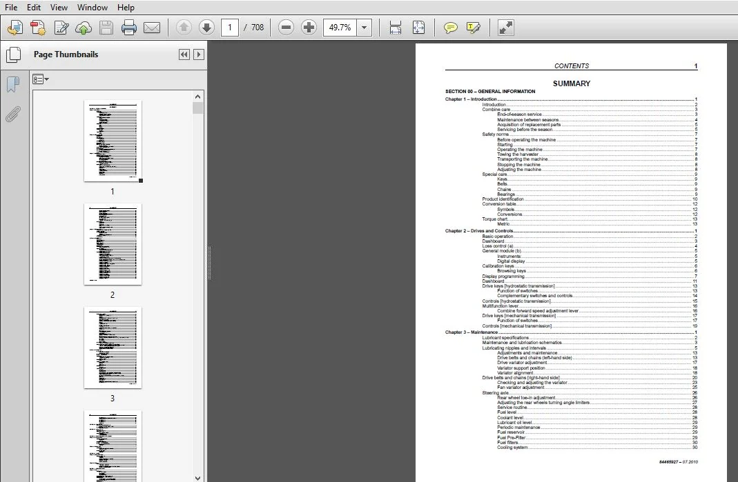
TABLE OF CONTENTS:
New Holland TC5070 Tractor Service Repair Manual (84270070)
Section 00 – GENERAL INFORMATION…………………………………………………… 14
Chapter 1 – Introduction………………………………………………………….. 14
INTRODUCTION…………………………………………………………………. 15
COMBINE CARE…………………………………………………………………. 16
END-OF-SEASON SERVICE……………………………………………………… 16
MAINTENANCE BETWEEN SEASONS………………………………………………… 17
ACQUISITION OF REPLACEMENT PARTS……………………………………………. 18
SERVICING BEFORE THE SEASON………………………………………………… 18
SAFETY NORMS…………………………………………………………………. 20
BEFORE OPERATING THE MACHINE……………………………………………….. 20
Starting…………………………………………………………………. 20
Operating the machine……………………………………………………… 20
TOWING THE HARVESTER………………………………………………………. 21
TRANSPORTING THE MACHINE…………………………………………………… 21
Stopping the machine………………………………………………………. 21
Adjusting the machine……………………………………………………… 21
SPECIAL CARE…………………………………………………………………. 22
KEYS…………………………………………………………………….. 22
BELTS……………………………………………………………………. 22
CHAINS…………………………………………………………………… 22
BEARINGS…………………………………………………………………. 22
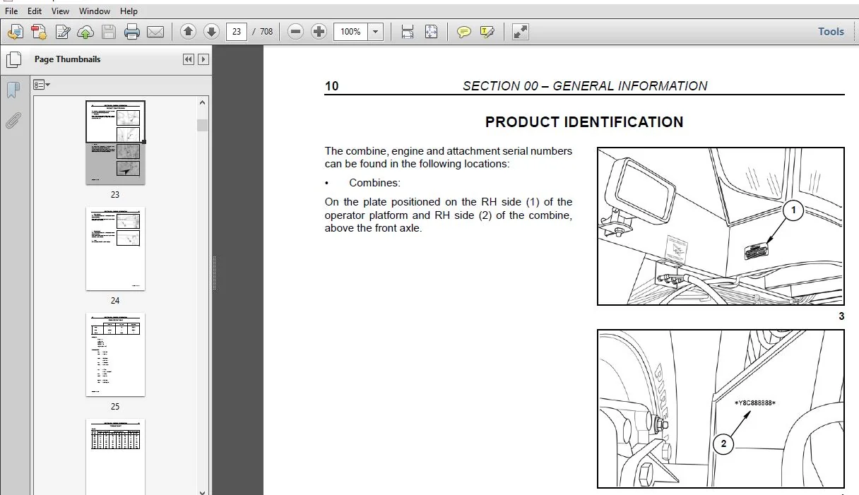
PRODUCT IDENTIFICATION………………………………………………………… 23
CONVERSION TABLE……………………………………………………………… 25
Symbols:…………………………………………………………………. 25
CONVERSIONS:……………………………………………………………… 25
TORQUE CHART…………………………………………………………………. 26
Metric…………………………………………………………………… 26
Chapter 2 – Drives and Controls……………………………………………………. 28
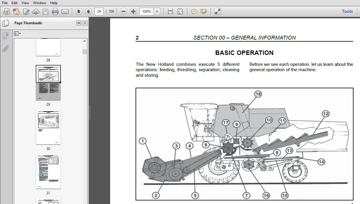
BASIC OPERATION………………………………………………………………. 29
DASHBOARD……………………………………………………………………. 30
LOSS CONTROL (A)……………………………………………………………… 31
General Module (B)……………………………………………………………. 32
Instruments:……………………………………………………………… 32
Digital Display…………………………………………………………… 32
CALIBRATION KEYS……………………………………………………………… 33
Browsing keys…………………………………………………………….. 33
DISPLAY PROGRAMMING…………………………………………………………… 34
DASHBOARD……………………………………………………………………. 38
DRIVE KEYS [hydrostatic transmission]…………………………………………… 40
Function of switches………………………………………………………. 40
Complementary Switches and Controls…………………………………………. 41
CONTROLS [hydrostatic transmission]…………………………………………….. 42
Multifunction Lever…………………………………………………………… 43
Combine forward speed adjustment lever………………………………………. 43
DRIVE KEYS [mechanical transmission]……………………………………………. 44
Function of switches………………………………………………………. 44
CONTROLS [mechanical transmission]……………………………………………… 46
Chapter 3 – Maintenance…………………………………………………………… 48
Lubricant specifications………………………………………………………. 49
MAINTENANCE AND LUBRICATION SCHEMATICS………………………………………….. 50
Lubricating nipples and intervals…………………………………………… 52
ADJUSTMENTS AND MAINTENANCE……………………………………………………. 61
Drive belts and chains (Left-hand side)……………………………………… 61
Drive variator adjustment………………………………………………….. 65
Variator Support Position………………………………………………….. 66
Variator Alignment………………………………………………………… 66
DRIVE BELTS AND CHAINS [right-hand side]………………………………………… 68
Checking and Adjusting the Variator…………………………………………. 71
Fan variator adjustment……………………………………………………. 73
STEERING AXLE………………………………………………………………… 74
Rear Wheel Toe-In Adjustment……………………………………………….. 74
Adjusting the Rear Wheels Turning Angle Limiters……………………………… 75
Service Routine…………………………………………………………… 76
Fuel level……………………………………………………………….. 76
Coolant level…………………………………………………………….. 76
Lubricant oil level……………………………………………………….. 77
Periodic maintenance………………………………………………………. 77
Fuel reservoir……………………………………………………………. 77
Fuel Pre-Filter…………………………………………………………… 77
Fuel filters……………………………………………………………… 78
Cooling system……………………………………………………………. 78
Cleaning the rotating screen……………………………………………….. 80
Cleaning the radiator……………………………………………………… 80
Air intake system…………………………………………………………. 81
Cleaning the pre-filter …………………………………………………… 81
Cleaning the primary filtering element………………………………………. 81
Element replacement……………………………………………………….. 82
Lubricant Oil Level……………………………………………………….. 83
Oil Change……………………………………………………………….. 83
Oil sump ventilation system………………………………………………… 84
Valve Clearances………………………………………………………….. 84
Head bolts……………………………………………………………….. 84
Precautions with the turbocharger…………………………………………… 84
AIR CONDITIONER………………………………………………………………. 85
Cab Air Filter……………………………………………………………. 85
Condenser………………………………………………………………… 85
Evaporator……………………………………………………………….. 85
Coolant charge and change………………………………………………….. 85
Charge…………………………………………………………………… 86
Coolant inspection and replacement………………………………………….. 86
Coolant hoses…………………………………………………………….. 86
Chapter 4 – Field Adjustment………………………………………………………. 89
Safety Precautions for Operating on Hills……………………………………….. 90
COMBINE ADJUSTMENTS…………………………………………………………… 91
MEASURING GRAIN LOSS………………………………………………………….. 94
Simplified Procedure………………………………………………………. 94
Example:…………………………………………………………………. 94
Specific Measurement Procedure……………………………………………… 94
LOSSES FROM THE MACHINE……………………………………………………….. 97
troubleshooting………………………………………………………………. 98
Section 10 – ENGINE……………………………………………………………….103
SPECIFICATIONS………………………………………………………………..105
ASSEMBLY DIMENSIONS……………………………………………………………106
TIGHTENING TORQUES…………………………………………………………….108
Special tools…………………………………………………………………113
Engine Cold Starting…………………………………………………………..113
Cooling System………………………………………………………………..114
Lubrication System…………………………………………………………….115
Fault diagnosis……………………………………………………………….116
Installing the engine on the trestle…………………………………………….119
Removing the turbocharger…………………………………………………..121
ENGINE DISASSEMBLY…………………………………………………………….121
Valve disassembly………………………………………………………….126
Replacing the cylinder block bushes………………………………………….132
Installing tappets and camshaft……………………………………………..133
Assembling the engine………………………………………………………….133
Installing oil sparger nozzles………………………………………………134
Installing the main bearings………………………………………………..134
Installing the main bearing covers…………………………………………..135
Assembling the piston/link conrod set………………………………………..136
Piston/link conrod coupling…………………………………………………136
Installing the rings……………………………………………………….136
Installing the piston/link conrod sets on the cylinder sleeves………………….137
Diagram for installing the piston/link conrod sets on the cylinder sleeves……….137
Camshaft sychronism………………………………………………………..138
Installing the synchronism gear box………………………………………….139
Installing the water pump…………………………………………………..140
Installing the oil pump…………………………………………………….140
Installing the engine sump sealing gasket…………………………………….142
Installing the engine oil sump………………………………………………142
Installing the engine flywheel………………………………………………142
Installing the oil filter head………………………………………………143
Installing the alternator…………………………………………………..144
Installing the cylinder head………………………………………………..145
Installing the rocker arm sets………………………………………………146
Installing the injection nozzles…………………………………………….147
Installing the valve cover………………………………………………….148
Installing the exhaust manifold……………………………………………..148
Installing the thermostat…………………………………………………..148
Installing the fan pulley…………………………………………………..149
Installing the alternator belt………………………………………………149
Installing the intake manifold………………………………………………149
Installing the pressure tube………………………………………………..151
Installing the turbocharger…………………………………………………153
Completing the engine………………………………………………………153
checking and measuring…………………………………………………………155
Cylinder block…………………………………………………………….155
Checking the head contact surface……………………………………………156
Tappets…………………………………………………………………..156
Crankshaft………………………………………………………………..157
Dimensions of main trunnions and the link conrod………………………………157
Main bushings clearance…………………………………………………….159
Checking the crankshaft thrust ring clearance…………………………………160
Checking the camshaft raising and alignment…………………………………..161
Bushes……………………………………………………………………161
Camshaft………………………………………………………………….161
Piston/Link Conrod Set……………………………………………………..162
Pistons…………………………………………………………………..164
Measuring piston diameter…………………………………………………..164
Piston pins……………………………………………………………….164
Conditions for correct coupling of the piston pin……………………………..164
Bushes……………………………………………………………………166
Torsion check……………………………………………………………..167
Warp check………………………………………………………………..167
Link conrod bushing clearance……………………………………………….168
Piston projection check…………………………………………………….169
Cylinder head……………………………………………………………..170
Cylinder head tightness check……………………………………………….170
Checking the cylinder head contact surface……………………………………170
Valves……………………………………………………………………171
Valve decarbonization, checking and overhauling……………………………….171
Checking the clearance between the valve rod and guide and centering the valve……171
Valve guides………………………………………………………………172
Valve seats……………………………………………………………….172
Valve springs……………………………………………………………..173
Rocker arm shaft…………………………………………………………..173
Valve clearance adjustment……………………………………………………..174
Procedure to remove the injection pump……………………………………….175
ROTARY injection pump removal, installation and synchronization…………………….175
Procedure to alter the injection pump static point arranged on a bench…………..180
Procedure to assemble the injection pump on the engine…………………………182
Cold start device operating test (kksb)………………………………………184
Deaeration (bleeding) the fuel system………………………………………..187
Checking injection pump synchronism………………………………………….187
Section 21 – TRANSMISSION………………………………………………………….191
Gearbox 3MD-35………………………………………………………………..192
Construction and Operation………………………………………………….192
List of Lubricants TE-ML.07…………………………………………………192
GEARBOX – TC5070 MECHANICAL…………………………………………………….193
GEARBOX – TC5070 HYDRO…………………………………………………………195
SPECIFICATIONS………………………………………………………………..197
Technical data and adjustment values…………………………………………197
Temperature for Assembly……………………………………………………197
Tightening Torques…………………………………………………………197
Disassembly Sequence…………………………………………………………..198
Cover…………………………………………………………………….198
Coupling and Inversion Carcass………………………………………………….199
Reverse Shaft……………………………………………………………..201
Idler Shaft……………………………………………………………….202
Drive Shaft……………………………………………………………….202
Differential Cover…………………………………………………………203
Differential………………………………………………………………….203
Differential………………………………………………………………204
Gearbox Carcass……………………………………………………………205
Assembly Sequence……………………………………………………………..205
Differential………………………………………………………………205
Gearbox Carcass……………………………………………………………207
Differential Cover…………………………………………………………208
Outer measurement of the differential cover (left-hand side)……………………209
Inner measurement of the differential cover (left-hand side)……………………209
Adjusting Differential Clearance…………………………………………….210
Measurement between the bearing and the carcass (left-hand side)………………..210
Drive Shaft……………………………………………………………….213
Idler Shaft……………………………………………………………….216
Reverse Shaft……………………………………………………………..218
Cover Adjustment…………………………………………………………..218
Fork assembly……………………………………………………………..219
Fork Setting………………………………………………………………220
Adjusting the Variator Shaft Bearing Axial Clearance…………………………..222
Measurement “A”……………………………………………………………222
Measurement “B”……………………………………………………………222
Adjusting the idler shaft bearing
axial clearance……………………………..223
Measurement “A”……………………………………………………………223
Measurement “B”……………………………………………………………223
Measurement “C”……………………………………………………………224
Measurement “D”……………………………………………………………224
Shift Cover……………………………………………………………….225
Section 22 – Drive clutch………………………………………………………….227
DRIVE CLUTCH [mechanical transmission]…………………………………………..228
Bleeding the clutch hydraulic command………………………………………..228
REAR WHEEL TOE-IN……………………………………………………………..229
Rear axle pivot positions…………………………………………………..229
Section 23 – Drive variator………………………………………………………..231
Belt Tension Adjustment………………………………………………………..232
Variator Adjustment……………………………………………………………232
Variator Support Position…………………………………………………..233
Variator Alignment…………………………………………………………….233
Vertical Alignment…………………………………………………………233
Horizontal Alignment……………………………………………………….233
Section 25 – FRONT MECHANICAL TRANSMISSION…………………………………………..235
Chapter 1 – Standard Final Drive……………………………………………………235
STANDARD REDUCER ratio 10/75……………………………………………………236
Disassembly……………………………………………………………….237
Assembly………………………………………………………………….237
WHEEL BOLT – REPLACEMENT……………………………………………………….238
FINAL DRIVE – Removal/Installation………………………………………………239
FINAL DRIVE – Disassembly/Assembly………………………………………………241
Disassembly……………………………………………………………….243
Assembly………………………………………………………………….243
Chapter 2 – Rice Final Drive……………………………………………………….246
Specifications………………………………………………………………..247
Technical Data and Adjustment Values…………………………………………247
Tightening Torques…………………………………………………………247
Rice Drive Ratio 10/75…………………………………………………………248
Disassembly……………………………………………………………….249
Assembly………………………………………………………………….249
Section 33 – BRAKES……………………………………………………………….250
Chapter 1 – Brake Pad Replacement…………………………………………………..250
BRAKE PAD REPLACEMENT………………………………………………………….251
Removal…………………………………………………………………..251
Installation………………………………………………………………251
Brake shoe disasembly and assembly…………………………………………..252
Brake disk disassembly……………………………………………………..252
Brake disk assembly………………………………………………………..252
Brake shoe assembly………………………………………………………..252
Chapter 2 – Brakes………………………………………………………………..254
BRAKES ………………………………………………………………………255
SERVICE BRAKE ADJUSTMENT……………………………………………………255
PARKING BRAKE ADJUSTMENT……………………………………………………255
BLEEDING THE CONNECTION BETWEEN THE TWO MAIN CYLINDERS…………………………256
BLEEDING THE RIGHT-HAND CIRCUIT……………………………………………..256
Section 35 – hydraulic system………………………………………………………258
Chapter 1 – Basics………………………………………………………………..258
specifications………………………………………………………………..259
FLOW RATE REDUCERS…………………………………………………………259
HYDRAULIC PUMP ……………………………………………………………260
Characteristics……………………………………………………………260
HYDRAULIC CYLINDERS………………………………………………………..260
HYDRAULIC SCHEMATICS – TC5070 Mechanical…………………………………………261
HYDRAULIC SCHEMATICS – TC5070 Hydro……………………………………………..262
HYDRAULIC SYSTEM………………………………………………………………263
TC5070 Combine [mechanical transmission]……………………………………..263
TC5070 Combine [hydrostatic transmission]…………………………………….264
HYDRAULIC CONTROL – FULL SET……………………………………………………265
HYDRAULIC CYLINDERS……………………………………………………………266
Disassembly/Assembly to change repair kit…………………………………….266
HYDROPNEUMATIC COMPENSATORS AND CYLINDERS………………………………………..267
Hydropneumatic compensators…………………………………………………267
Chapter 2 – Hydraulic Motors……………………………………………………….268
REVERSER HYDRAULIC MOTOR REMOVAL, INSTALLATION, DISASSEMBLY, INSPECTION AND ASSEMBLY….269
Preliminary Preparation
for Disassembly……………………………………..269
Removal and Installation……………………………………………………270
Removal…………………………………………………………………..270
Installation………………………………………………………………273
Disassembly and Inspection………………………………………………….275
Assembly………………………………………………………………….282
Final check……………………………………………………………….291
Rotor assembly…………………………………………………………….292
One Part Stator……………………………………………………………292
Practical maintenance tips for the
HYDRAULIC MOTOR – PARKER………………………..294
Chapter 3 – Steering………………………………………………………………296
SPECIAL TOOLS…………………………………………………………………297
SPECIFICATIONS………………………………………………………………..297
STEERING VALVE………………………………………………………………..298
Characteristics……………………………………………………………298
Removal…………………………………………………………………..299
Installation………………………………………………………………300
Disassembly……………………………………………………………….300
Assembly………………………………………………………………….305
PUMP GROUP……………………………………………………………………309
Main hydraulic pump………………………………………………………..310
Hydraulic pump (steering circuit)……………………………………………311
Hydraulic pump (side floating circuit)……………………………………….312
Chapter 4 – Hydrosatic System………………………………………………………354
GENERAL PRINCIPALS…………………………………………………………….355
Circuit ………………………………………………………………….355
Description and operation of the variable yield pump…………………………..355
Description and operation of the hydrostatic motor…………………………….357
Operation of the fixed displacement motor…………………………………….357
Rotating direction…………………………………………………………357
HYDROSTATIC TRANSMISSION……………………………………………………….358
Hydrostatic pump (cut view)…………………………………………………358
Hydrostatic motor (cut view)………………………………………………..359
HYDROSTATIC SYSTEM
(TC5070 Hydrostatic transmission)………………………………360
Technical Data…………………………………………………………….360
Hydrostatic system oil change and refilling…………………………………..360
Filling and bleeding the hydrostatic system…………………………………..360
Hydrostatic System mechanical adjsutments………………………………………..362
Adjust the control cable……………………………………………………362
Belt tension adjustment…………………………………………………….362
HYDROSTATIC CIRCUIT AND COMPONENTS………………………………………………363
MULTIFUNCTION VALVE……………………………………………………………366
Disassembling and assembling the main components………………………………….369
Troubleshooting and measurement points…………………………………………..369
Hydrostatic pump…………………………………………………………..369
Precautions……………………………………………………………….369
Retainer and shaft replacement………………………………………………369
Replacing the charge pressure relief valve……………………………………371
CHARGE PUMP……………………………………………………………….372
Replacing the charge pump…………………………………………………..372
Disassembly……………………………………………………………….372
Assembly………………………………………………………………….374
Replacing the control valve…………………………………………………375
Multifunction valves inspection and adjustment………………………………..376
Pressure valve adjusment……………………………………………………376
Bypass valves……………………………………………………………..376
Hydrostatic motor………………………………………………………….377
Replacing the shaft and retainer…………………………………………….377
Replacing the charge pressure relief valve……………………………………378
Replacing the shuttle valve…………………………………………………378
Chapter 5 – Auxiliary Drive I (4WD)…………………………………………………314
HYDROSTATIC CIRCUIT – AUXILIARY DRIVE……………………………………………315
How it Works………………………………………………………………316
Initial Yield Position (Drive system activated)……………………………….316
Maximum yield position……………………………………………………..317
Low neutral position……………………………………………………….317
Discharge position…………………………………………………………317
High Neutral Position………………………………………………………318
Wheel motor power distribution………………………………………………318
MAINTENANCE PROCEDURES…………………………………………………………320
Wheel-motor cut view……………………………………………………….320
Wheel-motor component………………………………………………………322
SHAFTS/GASKETS AND BEARINGS…………………………………………………….324
Disassembly……………………………………………………………….324
Assembly………………………………………………………………….330
Block and piston set…………………………………………………………..343
Disassembly……………………………………………………………….343
Assembly………………………………………………………………….347
DISTRIBUTOR (VALVE BLOCK) AND DISTRIBUTION GASKETS………………………………..348
Disassembly……………………………………………………………….348
Assembly………………………………………………………………….350
ACCUMULATOR…………………………………………………………………..352
Description and operation…………………………………………………..352
Disassembling the accumulator……………………………………………….352
Information to replace the accumulator……………………………………….353
Installing the accumulator………………………………………………….353
Chapter 6 – Auxiliary Drive II (4WD)………………………………………………..380
WHEEL MOTOR MAINTENANCE……………………………………………………………401
Preventive Maintenance and Precautions ………………………………………….401
General Recommendations………………………………………………………..401
TROUBLESHOOTING…………………………………………………………………..400
Wheel Motors………………………………………………………………….400
WHEEL MOTOR OPERATION……………………………………………………………..399
General Information……………………………………………………………399
Description…………………………………………………………………..399
DISASSEMBLY AND ASSEMBLY OF THE REAR AXLE……………………………………………398
Disassembly…………………………………………………………………..398
Assembly……………………………………………………………………..398
REAR AXLE MAINTENANCE……………………………………………………………..396
Basic maintenance requirements………………………………………………….396
Every 100 hours of Machine Operation:……………………………………………396
Cross-section…………………………………………………………………396
Every 100 hours of Machine Operation:……………………………………………397
STARTING PROCEDURE………………………………………………………………..395
TEST GAUGE LOCATIONS………………………………………………………………392
Test Procedure Nº 2……………………………………………………………392
Test Procedure Nº 3……………………………………………………………393
TESTING PROCEDURE…………………………………………………………………390
Test Procedure Nº 1……………………………………………………………390
Test Pressures versus Mode of Machine Operation…………………………………..391
Troubleshooting…………………………………………………………………..388
Fluidrive Rear Drive Systems……………………………………………………388
GENERAL INFORMATION……………………………………………………………….381
Safety Measures……………………………………………………………….381
Operation of the Fluidrive System……………………………………………….381
Chapter 7 – Troubleshooting………………………………………………………..402
Troubleshooting the Hydraulic Circuit……………………………………………403
Steering………………………………………………………………….403
Header……………………………………………………………………404
Reel……………………………………………………………………..405
Unloading Tube…………………………………………………………….405
Drive Variator…………………………………………………………….405
Lateral Flotation………………………………………………………….406
Reverser………………………………………………………………….406
Others……………………………………………………………………406
Section 36 – Pneumatic System………………………………………………………408
Chapter 1 – Pneumatic System……………………………………………………….408
SYMBOLS USED………………………………………………………………….409
HYDRAULIC CONTROL ROD ACTUATOR CYLINDER………………………………………….415
Installation of the sintered filter………………………………………….415
Installation kit…………………………………………………………..415
MICRO SOLENOID VALVE 3/2 PORTS – NC (Normally Closed)……………………………..416
TECHNICAL DATA…………………………………………………………….416
PNEUMATIC COMPONENTS…………………………………………………………..417
Solenoid Valve…………………………………………………………….417
Rotary Joint………………………………………………………………417
Drier Filter………………………………………………………………417
Pneumatic Cylinder…………………………………………………………417
Reverser Pneumatic Cylinder…………………………………………………418
Ball Valve………………………………………………………………..418
PNEUMATIC EQUIPMENT……………………………………………………………419
Selector Valve (“OR” Element)……………………………………………….419
Ball Valve………………………………………………………………..419
Reverser Control Valve……………………………………………………..419
PRESSURE REGULATOR…………………………………………………………….420
Schematic…………………………………………………………………420
Lubricator………………………………………………………………..421
PNEUMATIC SYSTEM………………………………………………………………422
PNEUMATIC SCHEMATIC……………………………………………………………423
Chapter 2 – Pneumatic components……………………………………………………424
Pneumatic clutch………………………………………………………………425
Removing the pneumatic clutch……………………………………………….425
Disassembling the pneumatic clutch…………………………………………..425
Assembling the pneumatic clutch……………………………………………..426
Disassembling the pneumatic clutch…………………………………………..434
Assembling the pneumatic clutch……………………………………………..437
Section 48 ‒ TRACKS……………………………………………………………….440
Specifications………………………………………………………………..441
Assembly Torques………………………………………………………………442
TRACKS……………………………………………………………………….443
New Holland Tracks for Rice Harvesters……………………………………….444
Introduction………………………………………………………………445
Front Axle………………………………………………………………..445
Rolling material…………………………………………………………..445
Straw elevator…………………………………………………………….445
Drive Wheels………………………………………………………………447
Shoes…………………………………………………………………….447
Attaching to the Harvester………………………………………………….448
Rear Tires………………………………………………………………..449
MAINTENANCE…………………………………………………………………..449
TRACK INSTALLATION…………………………………………………………….450
TOWING INSTRUCTIONS FOR HARVESTERS EQUIPPED WITH TRACKS……………………………454
Section 50 ‒ CLIMATE CONTROL/AIR CONDITIONER…………………………………………456
Chapter 1 – A/C SYSTEM…………………………………………………………….456
Introduction………………………………………………………………….457
Correct use of the air-conditioning system……………………………………458
Storage maintenance………………………………………………………..458
AIR CONDITIONING CIRCUIT……………………………………………………….459
Location of the A/C components………………………………………………460
Filter-drier (5)…………………………………………………………..460
Condenser (4)……………………………………………………………..460
Evaporator (7)…………………………………………………………….460
Compressor (1)…………………………………………………………….460
A/C CYCLE…………………………………………………………………….461
Air-conditioning process……………………………………………………461
Lubricants………………………………………………………………..462
Operation…………………………………………………………………462
COOLANT………………………………………………………………………463
Refrigerant recovery procedure………………………………………………463
Washing…………………………………………………………………..464
Recharge/Refilling…………………………………………………………464
Use of a manifold gauge set…………………………………………………464
Checking refrigerant for excess air………………………………………….465
Containers for the storage of recycled refrigerant…………………………….466
Transfer of refrigerant…………………………………………………….466
Disposal of empty or near empty disposable containers………………………….467
Applicable SAE standards……………………………………………………467
Related SAE standards………………………………………………………467
TESTING AND TROUBLESHOOTING, GENERAL…………………………………………….468
General safety and service precautions……………………………………….468
Check for leaks……………………………………………………………469
Cleanliness……………………………………………………………….469
Refilling…………………………………………………………………469
Contaminants………………………………………………………………470
Prevent mixing of service equipment………………………………………….470
PRELIMINARY TROUBLESHOOTING AND TESTING………………………………………….471
Operational checks ‒ Heating………………………………………………..471
Operational checks ‒ A/C……………………………………………………471
PRELIMINARY DIAGNOSTICS CHART…………………………………………………..472
TEST PROCEDURE ‒ STABILIZING THE SYSTEM TEST PORTS………………………………..473
A/C SYSTEM PERFORMANCE TEST AND DIAGNOSTICS CHART…………………………………474
GAUGE READINGS AND INTERPRETATIONS………………………………………………478
Chapter 2 – CONDENSER……………………………………………………………..490
Description…………………………………………………………………..491
Removal…………………………………………………………………..491
Installation………………………………………………………………492
Chapter 3 – FILTER DRIER…………………………………………………………..494
Description…………………………………………………………………..495
Troubleshooting……………………………………………………………495
Removal…………………………………………………………………..496
Installation………………………………………………………………496
Section 55 ‒ ELECTRICAL SYSTEM……………………………………………………..498
Chapter 1 ‒ Specifications…………………………………………………………498
SPECIFICATIONS………………………………………………………………..499
Chapter 2 ‒ Component Identification………………………………………………..500
SWITCHES……………………………………………………………………..501
Fuses and relays………………………………………………………………503
SUMMARY OF ALARMS……………………………………………………………..506
ALERT CONDITIONS………………………………………………………………508
Chapter 4 ‒ Troubleshooting Diagram…………………………………………………510
TROUBLESHOOTING……………………………………………………………….511
Chapter 5 ‒ Electric Schematics…………………………………………………….516
ELECTRICAL SYMBOLOGY…………………………………………………………..518
General…………………………………………………………………..518
Actuators or Consumers……………………………………………………..519
Generators and Storers……………………………………………………..520
Safety Elements……………………………………………………………520
Switches and Keys………………………………………………………….521
Relays……………………………………………………………………523
Panel Instruments………………………………………………………….523
Sensoring…………………………………………………………………524
Color code………………………………………………………………..524
Switches………………………………………………………………….525
ELECTRICAL SCHEMATICS………………………………………………………….526
BATTERY…………………………………………………………………..526
STARTING THE ENGINE………………………………………………………..527
ALTERNATOR/AIR RESTRICTION INDICATION………………………………………..528
IGINITION SWITCH…………………………………………………………..529
ENGINE MODULE……………………………………………………………..530
FUEL AND WATER LEVEL INDICATOR………………………………………………531
INDICATOR LIGHTS…………………………………………………………..532
INDICATOR LIGHTS/HORN………………………………………………………533
WORK LIGHTS/SIDE LIGHT……………………………………………………..534
DISTANCE LIGHTS/COURTESY LIGHT………………………………………………535
PARKING BRAKE/BRAKE LIGHTS………………………………………………….536
PARKING BRAKE/GRAIN TANK……………………………………………………537
MAIN LIGHTS……………………………………………………………….538
TRAFFIC WARNING LIGHTS……………………………………………………..539
REVERSE SOUND ALARM/REAR LIGHTS……………………………………………..540
WINDSCREEN WIPER…………………………………………………………..541
AIR CONDITIONER……………………………………………………………542
PNEUMATICS SAFETY CIRCUIT…………………………………………………..543
THRESHING ON………………………………………………………………544
HEADER ON…………………………………………………………………545
UNLOADING AUGER ON…………………………………………………………546
THRESHING CYLINDER VARIATOR…………………………………………………547
FAN VARIATOR………………………………………………………………548
REVERSER………………………………………………………………….549
OPEN AND CLOSE UNLOADING TUBE……………………………………………….550
LOWER HEADER………………………………………………………………551
SIDE FLOATING……………………………………………………………..552
VERTICAL REEL ADJUSTMENT……………………………………………………553
HORIZONTAL REEL ADJUSTMENT………………………………………………….554
REEL SPEED………………………………………………………………..555
CAAP / FL…………………………………………………………………556
LOSS MONITOR………………………………………………………………557
RPM SENSORS……………………………………………………………….558
ALARMS……………………………………………………………………559
SELF LEVELLING SIEVE……………………………………………………….560
4WD………………………………………………………………………561
RADIO…………………………………………………………………….562
Section 60 ‒ PRODUCT FEEDING……………………………………………………….563
Straw Elevator………………………………………………………………..564
Stone Trap……………………………………………………………………565
Cleanliness……………………………………………………………….565
Straw elevator removal……………………………………………………..565
STRAW ELEVATOR TRACK CHAINS…………………………………………………….566
Disassembly……………………………………………………………….566
Assembly………………………………………………………………….566
UPPER SHAFT…………………………………………………………………..567
Rear straw elevator shaft disassembly………………………………………..567
Rear straw elevator shaft assembly…………………………………………..567
Check the dimensional………………………………………………………….568
Straw elevator slip clutch disassembly……………………………………….568
Straw elevator slip clutch disassembly……………………………………….568
Section 66 ‒ THRESHING…………………………………………………………….569
Chapter 1 ‒ Cylinder and concave……………………………………………………569
THRESHING CYLINDER…………………………………………………………….570
Disassembly……………………………………………………………….570
Assembly………………………………………………………………….572
Cylinder balancing…………………………………………………………572
CONCAVES……………………………………………………………………..573
Concaves available…………………………………………………………573
Adjustments……………………………………………………………….573
TEETH CONCAVE OPENING (RICE)……………………………………………………575
Cylinder and Concave with Teeth……………………………………………..575
Accessing cylinder and concave………………………………………………575
Fine adjustment……………………………………………………………576
Concave replacement………………………………………………………..577
Dust plate………………………………………………………………..577
Section 72 ‒ Separation……………………………………………………………591
Chapter 1 ‒ Beater………………………………………………………………..591
BEATER……………………………………………………………………….592
Specifications…………………………………………………………….592
Cylinder type……………………………………………………………..592
Replacement of the shaft and the bearings…………………………………….593
Disassembly……………………………………………………………….593
Left side…………………………………………………………………594
Assembly………………………………………………………………….594
Chapter 2 ‒ Rotary Separator……………………………………………………….595
Rotary Separator………………………………………………………………596
Speed adjustments………………………………………………………….596
Procedure to replace the Rotary Separator…………………………………….597
Chapter 3 ‒ Straw Walker…………………………………………………………..599
Straw Walker………………………………………………………………….600
Fitting the crests…………………………………………………………600
Position of the crests……………………………………………………..601
Disassembly of the straw walker and shafts……………………………………602
Disassembly of the straw walker……………………………………………..602
Disassembly of the straw walker shafts……………………………………….602
Rear shaft………………………………………………………………..602
Front shaft……………………………………………………………….602
Assembly of the straw walker shafts………………………………………….603
Rear shaft………………………………………………………………..603
Front Axle………………………………………………………………..604
Care during shaft installation………………………………………………604
Straw walker bearings………………………………………………………604
Chapter 4 ‒ Grain pan……………………………………………………………..605
GRAIN PAN…………………………………………………………………….606
Characteristics……………………………………………………………606
Disassembly and assembly of the grain pan and the stone trap……………………607
Disassembly of the grain pan………………………………………………..607
Grain pan installation……………………………………………………..607
Section 74 – CLEANING……………………………………………………………..609
Fan………………………………………………………………………….610
CANVAS AIR DEFLECTOR…………………………………………………………..611
Replacement of the fan belts……………………………………………………612
Adjusting…………………………………………………………………612
VARIATOR ADJUSTMENT DEVICE……………………………………………………..613
Fan Case……………………………………………………………………..614
Disassembly……………………………………………………………….614
Left Side…………………………………………………………………614
Right Side………………………………………………………………..614
Assembly………………………………………………………………….614
SIEVES……………………………………………………………………….615
Types of sieve available……………………………………………………615
Factory sieve adjustment……………………………………………………616
Removing the sieves………………………………………………………..617
Installation………………………………………………………………617
Installation of the Upper Sieve with Self-Leveling System………………………618
Divider crests (1)…………………………………………………………619
With the Self-Leveling System……………………………………………….619
FITTING THE GRAIN PAN DIVIDERS………………………………………………….620
Procedure…………………………………………………………………620
Section 80 ‒ GRAIN STORAGE…………………………………………………………623
Grain and tailings auger……………………………………………………….624
Disassembly……………………………………………………………….624
Assembly………………………………………………………………….624
Leveling Auger and Tailings…………………………………………………….625
Tensioning of the grain/tailings elevator conveyor chains………………………625
Disassembly of the leveling auger……………………………………………626
Assembly………………………………………………………………….627
Disassembly of the tailings auger……………………………………………627
Assembly of the tailings auger………………………………………………627
Unloading tube auger…………………………………………………………..628
Disassembly of the unloading tube
and auger…………………………………..628
Installation of the unloading tube and auger………………………………….628
Adjustment of the unloading auger bearing…………………………………….629
Section 88 ‒ ACCESSORIES…………………………………………………………..631
Chapter 1 ‒ Straw Chopper………………………………………………………….631
STRAW CHOPPER…………………………………………………………………632
SPECIFICATIONS…………………………………………………………….632
OPERATION…………………………………………………………………632
Deflector…………………………………………………………………633
Straw guide vanes………………………………………………………….633
BELT TENSION ADJUSTMENT…………………………………………………….634
Front belt………………………………………………………………..634
Correct belt tension……………………………………………………….634
Rear Belt…………………………………………………………………634
STRAW CHOPPER SPEED ADJUSTMENT………………………………………………635
DEFLECTOR PLATE……………………………………………………………635
TROUBLESHOOTING……………………………………………………………….636
Section 90 ‒ HEADER, CAB, BODYWORK AND DECALS………………………………………..639
Chapter 1 ‒ Coupling grain header and corn spout……………………………………..639
CUTTING PLATFORM………………………………………………………………640
Specifications…………………………………………………………….640
Cutting platform coupling to the harvester……………………………………640
Uncoupling the cutting platform …………………………………………….642
Horizontal leveling of the platform………………………………………….643
Cutting platform…………………………………………………………..644
Flexible System……………………………………………………………644
C.A.A.P. Adjustment/F.3L……………………………………………………….645
CAAP Adjustment……………………………………………………………645
Lateral Flotation Adjustment………………………………………………..645
Lateral Flotation Components………………………………………………..645
BLADES AND BLADE BOX…………………………………………………………..647
Maintenance of the blade drive box…………………………………………..647
Oil Level…………………………………………………………………647
Oil Change………………………………………………………………..647
Knife Replacement………………………………………………………….648
Cutter Bar Alignment……………………………………………………….648
Blade Adjustment…………………………………………………………..648
REEL…………………………………………………………………………649
Leveling………………………………………………………………….649
Vertical adjustment………………………………………………………..649
Hydraulic Horizontal Adjustment……………………………………………..649
Bleeding of the horizontal adjustment hydraulic system…………………………649
Positioning of fingers……………………………………………………..650
Tensioning the drive chain………………………………………………….650
FEED AUGER……………………………………………………………………651
Drive…………………………………………………………………….651
Specifications…………………………………………………………….651
Flotation adjustment of the auger/retracting fingers…………………………..652
Chapter 2 ‒ Cutter bar drive box……………………………………………………655
Disassembly…………………………………………………………………..656
Assembly………………………………………………………………….658
TROUBLESHOOTING…………………………………………………………………..704
ADJUSTMENTS FOR THE CORN HARVEST……………………………………………………703
FIELD WORK……………………………………………………………………….702
ADJUSTMENTS AND MAINTENANCE………………………………………………………..701
LUBRICATING NIPPLES……………………………………………………………….699
Grease Nipples………………………………………………………………..699
Transmission Boxes…………………………………………………………….700
Chains……………………………………………………………………….700
Chain maintenance after the harvest……………………………………………..700
SERVICE SCHEDULE………………………………………………………………….698
LUBRICATION………………………………………………………………………698
ROW UNIT SAFETY CLUTCH (TORQUE LIMITER)……………………………………………..693
DISASSEMBLY OF THE GEARBOX AND ROW UNIT SAFETY CLUTCH……………………………..694
Gearbox………………………………………………………………………694
Removal of the gearbox…………………………………………………………695
Stalk rolls ‒ Synchronism of the pullers…………………………………………695
Gearbox disassembly……………………………………………………………696
Disassembly and assembly of the safety clutch…………………………………….696
Reinstallation of the divider points and dividers…………………………………697
Retaining bracket……………………………………………………………..697
Ear saver…………………………………………………………………….697
ROW UNIT TRANSMISSION BOX………………………………………………………….693
ARTICULATED DIVIDER POINTS…………………………………………………………690
Articulated Points…………………………………………………………….690
Drag Plates…………………………………………………………………..690
Angle of Inclination of Row Units……………………………………………….691
Vertical Inclination of the Row Units……………………………………………691
Row Unit Attachments…………………………………………………………..691
Row Unit Drive………………………………………………………………..692
SETTING THE DISTANCE BETWEEN ROWS…………………………………………………..686
SETTING THE ROW UNITS………………………………………………………….687
ROW UNIT GUARDS……………………………………………………………….689
REVERSER SYSTEM…………………………………………………………………..684
DECK PLATES…………………………………………………………………..685
LEFT SHIELD AND DEFLECTOR………………………………………………………685
ELECTRICAL CONTROL OF THE DECK PLATES……………………………………………….682
Corn Header Activation…………………………………………………………682
Corn Header Height Control [mechanical transmission]………………………………682
Corn Header Height Control [hydrostatic transmission]……………………………..682
Adjusting the Distance Between the Deck Plates……………………………………683
FEEDER AUGER AND ROW UNIT DRIVE…………………………………………………….680
Feeder auger with total helix in the center………………………………………680
Feeder auger height……………………………………………………………680
Adjustment of the safety clutch…………………………………………………681
FEEDER CHAINS…………………………………………………………………….674
Stalk rolls…………………………………………………………………..675
Replacement of the stalk rolls………………………………………………….677
Adjustment of the weed knives and the stalk rolls…………………………………678
Adjustments of the weed knives (Counter knives)…………………………………..678
Stalk roll adjustment………………………………………………………….679
PNEUMATIC SYSTEM………………………………………………………………….673
SIEVE……………………………………………………………………………672
FAN……………………………………………………………………………..671
STONE TRAP……………………………………………………………………….670
CONCAVE………………………………………………………………………….668
STRAW ELEVATOR ADJUSTMENTS…………………………………………………………667
Straw elevator chain tension……………………………………………………667
Adjustment of the front axle suspension spring……………………………………667
Chain………………………………………………………………………..667
STRAW ELEVATOR ‒ HEADER COUPLING……………………………………………………665
Support Shoes…………………………………………………………………665
Coupling the corn header to the combine………………………………………….666
HEADER SIZES……………………………………………………………………..663
REQUIRED PROCEDURES FOR CORN……………………………………………………664
SPECIFICATIONS……………………………………………………………………662
INTRODUCTION…………………………………………………………………….. 15
COMBINE CARE…………………………………………………………………….. 16
END-OF-SEASON SERVICE…………………………………………………………. 16
MAINTENANCE BETWEEN SEASONS……………………………………………………. 17
SERVICING BEFORE THE SEASON……………………………………………………. 18
SAFETY NORMS…………………………………………………………………….. 20
TOWING THE HARVESTER………………………………………………………….. 21
TRANSPORTING THE MACHINE………………………………………………………. 21
Stopping the machine………………………………………………………….. 21
Adjusting the machine…………………………………………………………. 21
SPECIAL CARE…………………………………………………………………….. 22
PRODUCT IDENTIFICATION……………………………………………………………. 23
CONVERSION TABLE…………………………………………………………………. 25
TORQUE CHART…………………………………………………………………….. 26
BASIC OPERATION………………………………………………………………….. 29
DASHBOARD……………………………………………………………………….. 30
LOSS CONTROL (A)…………………………………………………………………. 31
General Module (B)……………………………………………………………….. 32
Instruments:…………………………………………………………………. 32
CALIBRATION KEYS…………………………………………………………………. 33
DISPLAY PROGRAMMING………………………………………………………………. 34
DASHBOARD……………………………………………………………………….. 38
DRIVE KEYS [hydrostatic transmission]………………………………………………. 40
Function of switches………………………………………………………….. 40
Complementary Switches and Controls…………………………………………….. 41
CONTROLS [hydrostatic transmission]………………………………………………… 42
Multifunction Lever………………………………………………………………. 43
DRIVE KEYS [mechanical transmission]……………………………………………….. 44
Function of switches………………………………………………………….. 44
CONTROLS [mechanical transmission]…………………………………………………. 46
Safety Precautions for Operating on Hills…………………………………………… 90
COMBINE ADJUSTMENTS………………………………………………………………. 91
MEASURING GRAIN LOSS……………………………………………………………… 94
Simplified Procedure………………………………………………………….. 94
Specific Measurement Procedure…………………………………………………. 94
LOSSES FROM THE MACHINE…………………………………………………………… 97
troubleshooting………………………………………………………………….. 98
Gearbox 3MD-35……………………………………………………………………192
GEARBOX ‒ TC5070 MECHANICAL………………………………………………………..193
GEARBOX ‒ TC5070 HYDRO…………………………………………………………….195
SPECIFICATIONS……………………………………………………………………197
Technical data and adjustment values…………………………………………….197
Temperature for Assembly……………………………………………………….197
Tightening Torques…………………………………………………………….197
Disassembly Sequence………………………………………………………………198
Coupling and Inversion Carcass……………………………………………………..199
Idler Shaft…………………………………………………………………..202
Drive Shaft…………………………………………………………………..202
Differential Cover…………………………………………………………….203
Differential……………………………………………………………………..203
Differential………………………………………………………………….204
Gearbox Carcass……………………………………………………………….205
Assembly Sequence…………………………………………………………………205
Differential………………………………………………………………….205
Gearbox Carcass……………………………………………………………….207
Differential Cover…………………………………………………………….208
Drive Shaft…………………………………………………………………..213
Idler Shaft…………………………………………………………………..216
Reverse Shaft…………………………………………………………………218
Cover Adjustment………………………………………………………………218
Fork assembly…………………………………………………………………219
Fork Setting………………………………………………………………….220
Adjusting the Variator Shaft Bearing Axial Clearance………………………………222
Adjusting the idler shaft bearing axial clearance…………………………………223
Shift Cover…………………………………………………………………..225
DRIVE CLUTCH [mechanical transmission]………………………………………………228
Bleeding the clutch hydraulic command……………………………………………228
REAR WHEEL TOE-IN…………………………………………………………………229
Rear axle pivot positions………………………………………………………229
Belt Tension Adjustment……………………………………………………………232
Variator Adjustment……………………………………………………………….232
Variator Alignment………………………………………………………………..233
Specifications……………………………………………………………………247
Rice Drive Ratio 10/75…………………………………………………………….248
Disassembly…………………………………………………………………..249
Assembly……………………………………………………………………..249
BRAKE PAD REPLACEMENT……………………………………………………………..251
Removal………………………………………………………………………251
Installation………………………………………………………………….251
Brake shoe disasembly and assembly………………………………………………252
BRAKES ………………………………………………………………………….255
SERVICE BRAKE ADJUSTMENT……………………………………………………….255
PARKING BRAKE ADJUSTMENT……………………………………………………….255
BLEEDING THE CONNECTION BETWEEN THE TWO MAIN CYLINDERS…………………………….256
BLEEDING THE RIGHT-HAND CIRCUIT…………………………………………………256
REVERSER HYDRAULIC MOTOR REMOVAL, INSTALLATION, DISASSEMBLY, INSPECTION AND ASSEMBLY……..269
Preliminary Preparation for Disassembly………………………………………….269
Removal and Installation……………………………………………………….270
Disassembly and Inspection……………………………………………………..275
Assembly……………………………………………………………………..282
Final check…………………………………………………………………..291
Rotor assembly………………………………………………………………..292
Practical maintenance tips for the
HYDRAULIC MOTOR ‒ PARKER……………………………294
SPECIAL TOOLS…………………………………………………………………….297
SPECIFICATIONS……………………………………………………………………297
STEERING VALVE……………………………………………………………………298
Characteristics……………………………………………………………….298
Removal………………………………………………………………………299
Installation………………………………………………………………….300
Disassembly…………………………………………………………………..300
Assembly……………………………………………………………………..305
PUMP GROUP……………………………………………………………………….309
Main hydraulic pump……………………………………………………………310
Hydraulic pump (steering circuit)……………………………………………….311
Hydraulic pump (side floating circuit)…………………………………………..312
HYDROSTATIC CIRCUIT – AUXILIARY DRIVE……………………………………………….315
How it Works………………………………………………………………….316
MAINTENANCE PROCEDURES…………………………………………………………….320
Wheel–motor cut view…………………………………………………………..320
Wheel–motor component………………………………………………………….322
SHAFTS/GASKETS AND BEARINGS………………………………………………………..324
Disassembly…………………………………………………………………..324
Assembly……………………………………………………………………..330
Block and piston set………………………………………………………………343
Disassembly…………………………………………………………………..343
Assembly……………………………………………………………………..347
DISTRIBUTOR (VALVE BLOCK) AND DISTRIBUTION GASKETS……………………………………348
Disassembly…………………………………………………………………..348
Assembly……………………………………………………………………..350
ACCUMULATOR………………………………………………………………………352
Description and operation………………………………………………………352
Disassembling the accumulator…………………………………………………..352
Information to replace the accumulator…………………………………………..353
Installing the accumulator……………………………………………………..353
GENERAL PRINCIPALS………………………………………………………………..355
Circuit ……………………………………………………………………..355
Description and operation of the variable yield pump………………………………355
Description and operation of the hydrostatic motor………………………………..357
Operation of the fixed displacement motor………………………………………..357
Rotating direction…………………………………………………………….357
HYDROSTATIC TRANSMISSION…………………………………………………………..358
Hydrostatic pump (cut view)…………………………………………………….358
Hydrostatic motor (cut view)……………………………………………………359
HYDROSTATIC SYSTEM (TC5070 Hydrostatic transmission)………………………………….360
Technical Data………………………………………………………………..360
Hydrostatic system oil change and refilling………………………………………360
Hydrostatic System mechanical adjsutments……………………………………………362
Adjust the control cable……………………………………………………….362
Belt tension adjustment………………………………………………………..362
HYDROSTATIC CIRCUIT AND COMPONENTS………………………………………………….363
MULTIFUNCTION VALVE……………………………………………………………….366
Disassembling and assembling the main components……………………………………..369
Troubleshooting and measurement points………………………………………………369
Hydrostatic pump………………………………………………………………369
CHARGE PUMP…………………………………………………………………..372
Disassembly…………………………………………………………………..372
Assembly……………………………………………………………………..374
Hydrostatic motor……………………………………………………………..377
GENERAL INFORMATION……………………………………………………………….381
Safety Measures……………………………………………………………….381
Operation of the Fluidrive System……………………………………………….381
Troubleshooting…………………………………………………………………..388
Fluidrive Rear Drive Systems……………………………………………………388
TESTING PROCEDURE…………………………………………………………………390
Test Procedure Nº 1……………………………………………………………390
Test Pressures versus Mode of Machine Operation…………………………………..391
TEST GAUGE LOCATIONS………………………………………………………………392
Test Procedure Nº 2……………………………………………………………392
Test Procedure Nº 3……………………………………………………………393
STARTING PROCEDURE………………………………………………………………..395
REAR AXLE MAINTENANCE……………………………………………………………..396
Basic maintenance requirements………………………………………………….396
DISASSEMBLY AND ASSEMBLY OF THE REAR AXLE……………………………………………398
Disassembly…………………………………………………………………..398
Assembly……………………………………………………………………..398
WHEEL MOTOR OPERATION……………………………………………………………..399
General Information……………………………………………………………399
TROUBLESHOOTING…………………………………………………………………..400
Wheel Motors………………………………………………………………….400
WHEEL MOTOR MAINTENANCE……………………………………………………………401
Preventive Maintenance and Precautions ………………………………………….401
Troubleshooting the Hydraulic Circuit……………………………………………….403
Steering……………………………………………………………………..403
Header……………………………………………………………………….404
Reel…………………………………………………………………………405
Unloading Tube………………………………………………………………..405
Drive Variator………………………………………………………………..405
Lateral Flotation……………………………………………………………..406
Reverser……………………………………………………………………..406
Others……………………………………………………………………….406
SYMBOLS USED……………………………………………………………………..409
HYDRAULIC CONTROL ROD ACTUATOR CYLINDER……………………………………………..415
Installation of the sintered filter……………………………………………..415
MICRO SOLENOID VALVE 3/2 PORTS – NC (Normally Closed)…………………………………416
PNEUMATIC COMPONENTS………………………………………………………………417
Solenoid Valve………………………………………………………………..417
Rotary Joint………………………………………………………………….417
Drier Filter………………………………………………………………….417
Pneumatic Cylinder…………………………………………………………….417
Reverser Pneumatic Cylinder…………………………………………………….418
Ball Valve……………………………………………………………………418
PNEUMATIC EQUIPMENT……………………………………………………………….419
Selector Valve (“OR” Element)…………………………………………………..419
Ball Valve……………………………………………………………………419
Reverser Control Valve…………………………………………………………419
PRESSURE REGULATOR………………………………………………………………..420
Schematic…………………………………………………………………….420
Lubricator……………………………………………………………………421
PNEUMATIC SYSTEM………………………………………………………………….422
PNEUMATIC SCHEMATIC……………………………………………………………….423
Pneumatic clutch………………………………………………………………….425
Removing the pneumatic clutch…………………………………………………..425
Disassembling the pneumatic clutch………………………………………………425
Assembling the pneumatic clutch…………………………………………………426
Disassembling the pneumatic clutch………………………………………………434
Assembling the pneumatic clutch…………………………………………………437
Specifications……………………………………………………………………441
Assembly Torques………………………………………………………………….442
TRACKS…………………………………………………………………………..443
New Holland Tracks for Rice Harvesters…………………………………………..444
Introduction………………………………………………………………….445
Front Axle……………………………………………………………………445
Rolling material………………………………………………………………445
Straw elevator………………………………………………………………..445
Drive Wheels………………………………………………………………….447
Shoes………………………………………………………………………..447
Attaching to the Harvester……………………………………………………..448
Rear Tires……………………………………………………………………449
MAINTENANCE………………………………………………………………………449
TRACK INSTALLATION………………………………………………………………..450
TOWING INSTRUCTIONS FOR HARVESTERS EQUIPPED WITH TRACKS……………………………….454
Introduction……………………………………………………………………..457
Correct use of the air-conditioning system……………………………………….458
Storage maintenance……………………………………………………………458
AIR CONDITIONING CIRCUIT…………………………………………………………..459
Location of the A/C components………………………………………………….460
A/C CYCLE………………………………………………………………………..461
Air-conditioning process……………………………………………………….461
Lubricants……………………………………………………………………462
Operation…………………………………………………………………….462
COOLANT………………………………………………………………………….463
Refrigerant recovery procedure………………………………………………….463
Washing………………………………………………………………………464
Recharge/Refilling…………………………………………………………….464
Use of a manifold gauge set…………………………………………………….464
Checking refrigerant for excess air……………………………………………..465
Containers for the storage of recycled refrigerant………………………………..466
Transfer of refrigerant………………………………………………………..466
Disposal of empty or near empty disposable containers……………………………..467
Applicable SAE standards……………………………………………………….467
Related SAE standards………………………………………………………….467
TESTING AND TROUBLESHOOTING, GENERAL………………………………………………..468
General safety and service precautions…………………………………………..468
Check for leaks……………………………………………………………….469
Cleanliness…………………………………………………………………..469
Refilling…………………………………………………………………….469
Contaminants………………………………………………………………….470
Prevent mixing of service equipment……………………………………………..470
PRELIMINARY TROUBLESHOOTING AND TESTING……………………………………………..471
Operational checks ‒ Heating……………………………………………………471
Operational checks ‒ A/C……………………………………………………….471
PRELIMINARY DIAGNOSTICS CHART………………………………………………………472
TEST PROCEDURE ‒ STABILIZING THE SYSTEM TEST PORTS……………………………………473
A/C SYSTEM PERFORMANCE TEST AND DIAGNOSTICS CHART…………………………………….474
GAUGE READINGS AND INTERPRETATIONS………………………………………………….478
Description………………………………………………………………………491
Removal………………………………………………………………………….491
Installation……………………………………………………………………..492
Description………………………………………………………………………495
Troubleshooting…………………………………………………………………..495
Removal………………………………………………………………………….496
Installation……………………………………………………………………..496
SPECIFICATIONS……………………………………………………………………499
SWITCHES…………………………………………………………………………501
Fuses and relays………………………………………………………………….503
SUMMARY OF ALARMS…………………………………………………………………506
ALERT CONDITIONS………………………………………………………………….508
Cylinder VARIATOR BELT ‒ Removal/Installation………………………………………..580
THRESHING CYLINDER VARIATOR DRIVEN DISKS ‒
Removal/Installation………………………..583
Threshing cylinder variator drive disks ‒
Removal/Installation…………………………587
CYLINDER VARIATOR ADJUSTMENT……………………………………………………….590
BEATER…………………………………………………………………………..592
Specifications………………………………………………………………..592
Replacement of the shaft and the bearings………………………………………..593
Rotary Separator………………………………………………………………….596
Speed adjustments……………………………………………………………..596
Procedure to replace the Rotary Separator………………………………………..597
Straw Walker……………………………………………………………………..600
Fitting the crests…………………………………………………………….600
Position of the crests…………………………………………………………601
Disassembly of the straw walker and shafts……………………………………….602
Assembly of the straw walker shafts……………………………………………..603
Care during shaft installation………………………………………………….604
Straw walker bearings………………………………………………………….604
GRAIN PAN………………………………………………………………………..606
Characteristics……………………………………………………………….606
Disassembly and assembly of the grain pan and the stone trap……………………….607
Fan……………………………………………………………………………..610
CANVAS AIR DEFLECTOR………………………………………………………………611
Replacement of the fan belts……………………………………………………….612
VARIATOR ADJUSTMENT DEVICE…………………………………………………………613
Fan Case…………………………………………………………………………614
Disassembly…………………………………………………………………..614
Assembly……………………………………………………………………..614
SIEVES…………………………………………………………………………..615
Types of sieve available……………………………………………………….615
Factory sieve adjustment……………………………………………………….616
Removing the sieves……………………………………………………………617
Installation………………………………………………………………….617
Installation of the Upper Sieve with Self-Leveling System………………………….618
FITTING THE GRAIN PAN DIVIDERS……………………………………………………..620
Grain and tailings auger…………………………………………………………..624
Disassembly…………………………………………………………………..624
Assembly……………………………………………………………………..624
Leveling Auger and Tailings………………………………………………………..625
Tensioning of the grain/tailings elevator conveyor chains………………………….625
Disassembly of the leveling auger……………………………………………….626
Assembly……………………………………………………………………..627
Disassembly of the tailings auger……………………………………………….627
Assembly of the tailings auger………………………………………………….627
Unloading tube auger………………………………………………………………628
Disassembly of the unloading tube
and auger………………………………………628
Installation of the unloading tube and auger……………………………………..628
Adjustment of the unloading auger bearing………………………………………..629
STRAW CHOPPER…………………………………………………………………….632
SPECIFICATIONS………………………………………………………………..632
OPERATION…………………………………………………………………….632
Deflector…………………………………………………………………….633
Straw guide vanes……………………………………………………………..633
BELT TENSION ADJUSTMENT………………………………………………………..634
Front belt……………………………………………………………………634
STRAW CHOPPER SPEED ADJUSTMENT………………………………………………….635
DEFLECTOR PLATE……………………………………………………………….635
TROUBLESHOOTING…………………………………………………………………..636
CUTTING PLATFORM………………………………………………………………….640
Specifications………………………………………………………………..640
Cutting platform coupling to the harvester……………………………………….640
Uncoupling the cutting platform ………………………………………………..642
Horizontal leveling of the platform……………………………………………..643
Cutting platform………………………………………………………………644
C.A.A.P. Adjustment/F.3L…………………………………………………………..645
CAAP Adjustment……………………………………………………………….645
Lateral Flotation Adjustment……………………………………………………645
BLADES AND BLADE BOX………………………………………………………………647
Maintenance of the blade drive box………………………………………………647
Knife Replacement……………………………………………………………..648
Cutter Bar Alignment…………………………………………………………..648
Blade Adjustment………………………………………………………………648
REEL…………………………………………………………………………….649
Leveling……………………………………………………………………..649
Vertical adjustment……………………………………………………………649
Hydraulic Horizontal Adjustment…………………………………………………649
Positioning of fingers…………………………………………………………650
Tensioning the drive chain……………………………………………………..650
FEED AUGER……………………………………………………………………….651
Drive………………………………………………………………………..651
Specifications………………………………………………………………..651
Flotation adjustment of the auger/retracting fingers………………………………652
Disassembly………………………………………………………………………656
Assembly…………………………………………………………………………658
SPECIFICATIONS……………………………………………………………………662
HEADER SIZES……………………………………………………………………..663
STRAW ELEVATOR ‒ HEADER COUPLING……………………………………………………665
Support Shoes…………………………………………………………………665
STRAW ELEVATOR ADJUSTMENTS…………………………………………………………667
CONCAVE………………………………………………………………………….668
STONE TRAP……………………………………………………………………….670
FAN……………………………………………………………………………..671
SIEVE……………………………………………………………………………672
PNEUMATIC SYSTEM………………………………………………………………….673
FEEDER CHAINS…………………………………………………………………….674
Stalk rolls…………………………………………………………………..675
Replacement of the stalk rolls………………………………………………….677
Adjustment of the weed knives and the stalk rolls…………………………………678
FEEDER AUGER AND ROW UNIT DRIVE…………………………………………………….680
Feeder auger with total helix in the center………………………………………680
Feeder auger height……………………………………………………………680
Adjustment of the safety clutch…………………………………………………681
ELECTRICAL CONTROL OF THE DECK PLATES……………………………………………….682
Corn Header Activation…………………………………………………………682
Corn Header Height Control [mechanical transmission]………………………………682
Corn Header Height Control [hydrostatic transmission]……………………………..682
Adjusting the Distance Between the Deck Plates……………………………………683
REVERSER SYSTEM…………………………………………………………………..684
DECK PLATES…………………………………………………………………..685
LEFT SHIELD AND DEFLECTOR………………………………………………………685
SETTING THE DISTANCE BETWEEN ROWS…………………………………………………..686
ARTICULATED DIVIDER POINTS…………………………………………………………690
ROW UNIT TRANSMISSION BOX………………………………………………………….693
ROW UNIT SAFETY CLUTCH (TORQUE LIMITER)……………………………………………..693
DISASSEMBLY OF THE GEARBOX AND ROW UNIT SAFETY CLUTCH……………………………..694
LUBRICATION………………………………………………………………………698
SERVICE SCHEDULE………………………………………………………………….698
LUBRICATING NIPPLES……………………………………………………………….699
Grease Nipples………………………………………………………………..699
Transmission Boxes…………………………………………………………….700
Chains……………………………………………………………………….700
ADJUSTMENTS AND MAINTENANCE………………………………………………………..701
FIELD WORK……………………………………………………………………….702
ADJUSTMENTS FOR THE CORN HARVEST……………………………………………………703
TROUBLESHOOTING…………………………………………………………………..704
PLEASE NOTE:
- This is the same manual used by the dealers to diagnose and troubleshoot your vehicle
- You will be directed to the download page as soon as the purchase is completed. The whole payment and downloading process will take anywhere between 2-5 minutes
- Need any other service / repair / parts manual, please feel free to contact [email protected] . We still have 50,000 manuals unlisted