MTU Propulsion plant Remote Control System RCS-5 FPP 01-03 B Operation Manual E531942-01E PDF DOWNLOAD
$27.95
MTU Propulsion plant Remote Control System RCS-5 FPP 01-03 B Operation Manual E531942-01E PDF DOWNLOAD
Propulsion plant
Remote Control System
RCS-5 FPP 01-03/B
E 531 942 / 01 E
Documentation Parts 1, 2
Description
MTU Propulsion plant Remote Control System RCS-5 FPP 01-03 B Operation Manual E531942-01E PDF DOWNLOAD
FILE DETAILS:
MTU Propulsion plant Remote Control System RCS-5 FPP 01-03 B Operation Manual E531942-01E PDF DOWNLOAD
Language : English
Pages : 166
Downloadable : Yes
File Type : PDF
IMAGES PREVIEW OF THE MANUAL:
Questions? Email us: [email protected]
https://vimeo.com/858944177?share=copy
DESCRIPTION:
MTU Propulsion plant Remote Control System RCS-5 FPP 01-03 B Operation Manual E531942-01E PDF DOWNLOAD
General Information about Documentation
Documentation Structure
| Documentation Part | Title/Contents | Target Group(s) |
|---|---|---|
| 1 | Structure and function | Operating personnel, etc. |
| 2 | Operation | Operating personnel |
| 3 | Maintenance and repair | Plant personnel |
| 4 | Service manual | Electronic service personnel |
| 5 | Illustrated parts catalog | Operating personnel, electronic service personnel, logistics personnel |
| 6 | Plant-specific configuration | Electronic service personnel, installation personnel, start-up personnel |
| 7 | Mechanical and electrical installation | Installation personnel (electromechanical/mechatronic engineer) |
| 8 | Initial start-up | Start-up personnel |
Note: Not all parts of the documentation are written for every product.
TABLE OF CONTENTS:
MTU Propulsion plant Remote Control System RCS-5 FPP 01-03 B Operation Manual E531942-01E PDF DOWNLOAD
Propulsion plant
Remote Control System
RCS-5 FPP 01-03/B
E 531 942 / 01 E
Documentation Parts 1, 2
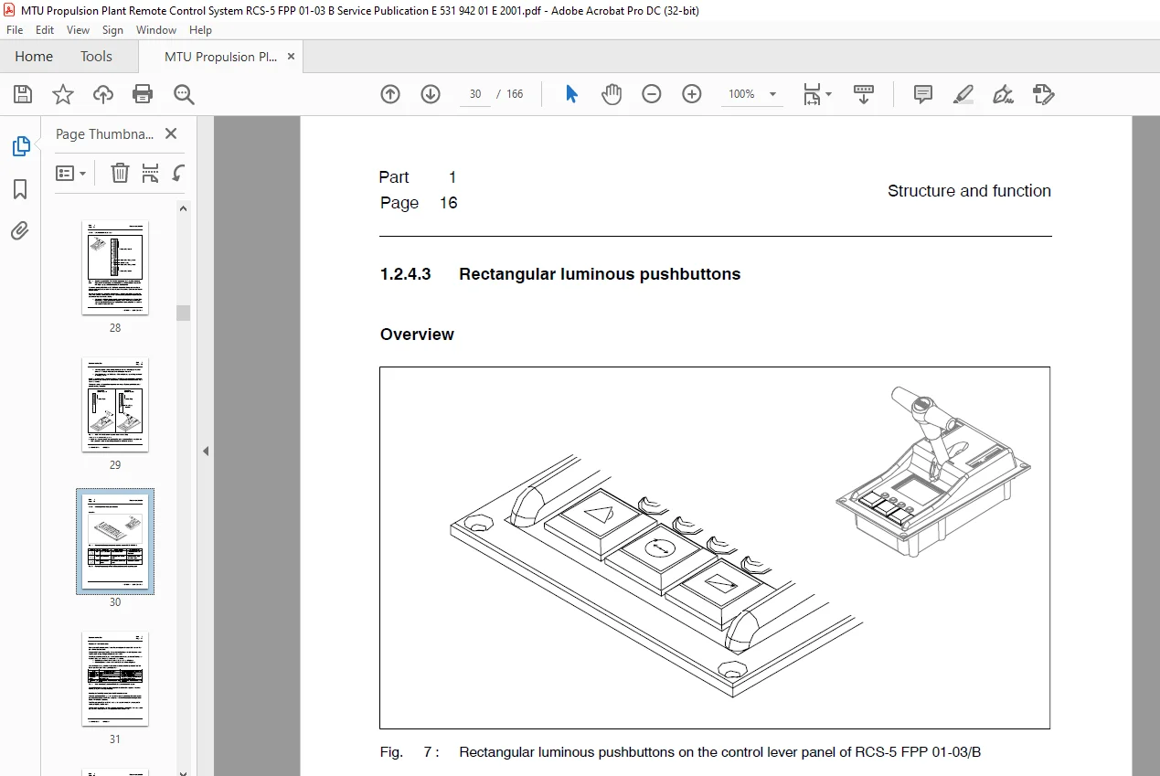
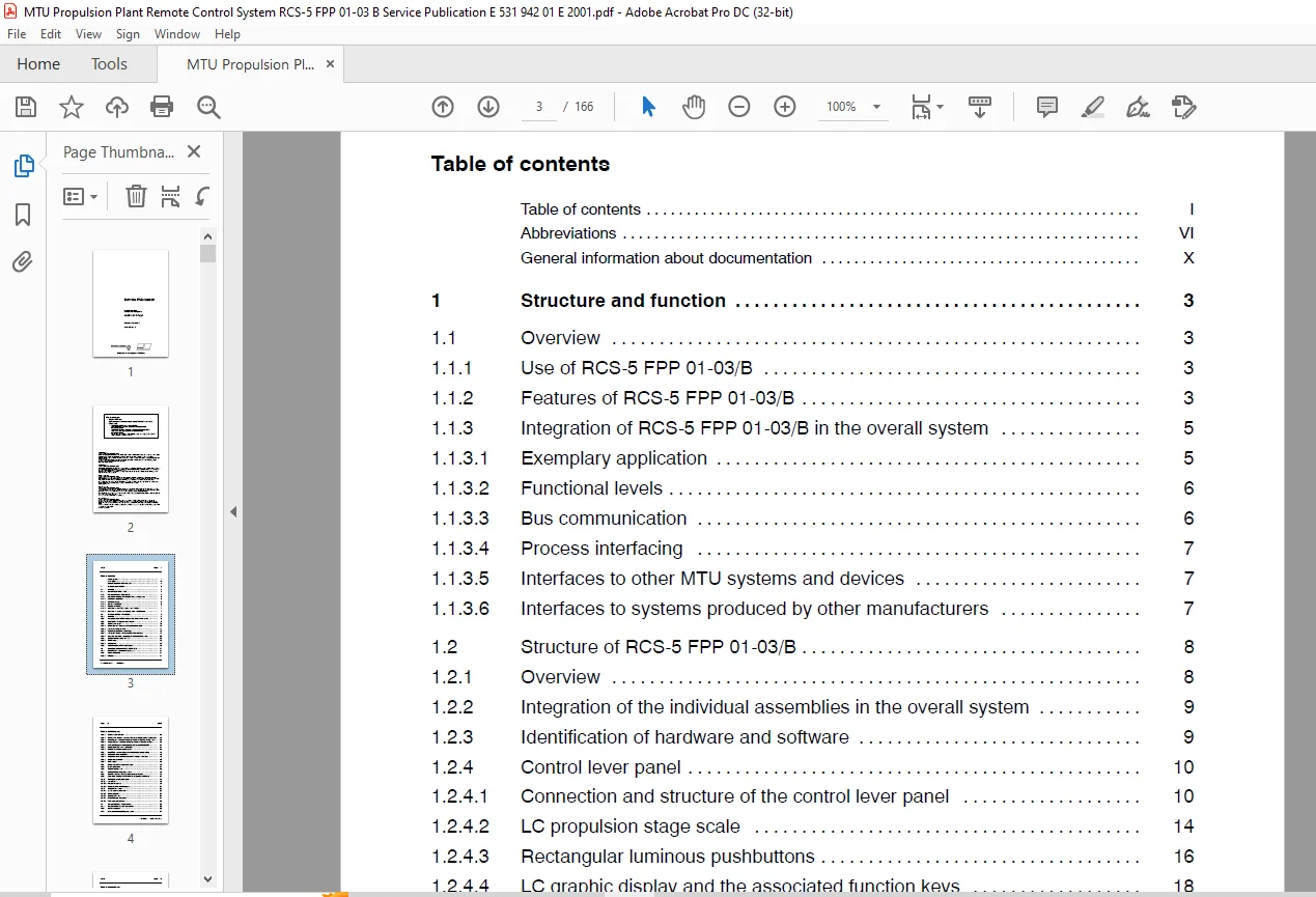
Title........................................................................................................................................  1
Guide........................................................................................................................................  3
	Table of contents........................................................................................................................  3
	Abbreviations............................................................................................................................  8
	General information about documentation.................................................................................................. 12
Part 1 Structure and function................................................................................................................ 15
	1 Structure and function................................................................................................................. 17
		1.1 Overview......................................................................................................................... 17
			1.1.1 Use of RCS-5 FPP 01-03/B................................................................................................... 17
			1.1.2 Features of RCS-5 FPP 01-03/B.............................................................................................. 17
			1.1.3 Integration of RCS-5 FPP 01-03/B in the overall system..................................................................... 19
				1.1.3.1 Exemplary application................................................................................................ 19
				1.1.3.2 Functional levels.................................................................................................... 20
				1.1.3.3 Bus communication.................................................................................................... 20
				1.1.3.4 Process interfacing.................................................................................................. 21
				1.1.3.5 Interfaces to other MTU systems and devices.......................................................................... 21
				1.1.3.6 Interfaces to systems produced by other manufacturers................................................................ 21
		1.2 Structure of RCS-5 FPP 01-03/B................................................................................................... 22
			1.2.1 Overview................................................................................................................... 22
			1.2.2 Integration of the individual assemblies in the overall system............................................................. 23
			1.2.3 Identification of hardware and software.................................................................................... 23
			1.2.4 Control lever panel........................................................................................................ 24
				1.2.4.1 Connection and structure of the control lever panel.................................................................. 24
				1.2.4.2 LC propulsion stage scale............................................................................................ 28
				1.2.4.3 Rectangular luminous pushbuttons..................................................................................... 30
				1.2.4.4 LC graphic display and the associated function keys.................................................................. 32
				1.2.4.5 Interfaces and cable connections of the control lever panel.......................................................... 49
			1.2.5 Option: Trolling Control Unit TCU.......................................................................................... 50
				1.2.5.1 Terminal box......................................................................................................... 50
				1.2.5.2 Trolling PIM......................................................................................................... 50
			1.2.6 Option: Additional PAN control panels...................................................................................... 50
		1.3 Operating functions of RCS-5 FPP 01-03/B......................................................................................... 51
			1.3.1 Assuming command after switching on........................................................................................ 51
			1.3.2 Command transfer........................................................................................................... 51
				1.3.2.1 Initiation........................................................................................................... 51
				1.3.2.2 Control station priorities........................................................................................... 52
				1.3.2.3 Control lever requirement, slave display, transitional phase and timeout............................................. 54
				1.3.2.4 Assuming command when the target control station has priority 1 or 2................................................. 56
				1.3.2.5 Requesting command when the target control station has priority 3.................................................... 57
				1.3.2.6 Relinquishing command (regardless of control station priority)....................................................... 58
				1.3.2.7 Special cases for command transfer................................................................................... 58
				1.3.2.8 Option: “Parallel command transfer”.................................................................................. 59
			1.3.3 Acquisition and processing of the control lever handle setting............................................................. 60
				1.3.3.1 Propulsion stage acquisition......................................................................................... 60
				1.3.3.2 Propulsion curves and engagement/disengagement ranges................................................................ 60
				1.3.3.3 Engine speed control................................................................................................. 62
				1.3.3.4 Gear control......................................................................................................... 62
			1.3.4 Single control lever mode (SCL mode)....................................................................................... 64
			1.3.5 Warm-up function........................................................................................................... 68
			1.3.6 Option: Trolling mode...................................................................................................... 69
			1.3.7 Option: Additional operating modes......................................................................................... 70
			1.3.8 Changing between Remote control and Local mode............................................................................. 71
			1.3.9 Responses of RCS-5 FPP 01-03/B to emergency engine stop.................................................................... 72
			1.3.10 Testing and monitoring features........................................................................................... 73
				1.3.10.1 Lamp test........................................................................................................... 73
				1.3.10.2 Integral Test System................................................................................................ 73
				1.3.10.3 Fault categories and fault codes.................................................................................... 75
			1.3.11 Signalling and alarms..................................................................................................... 76
				1.3.11.1 Types, sources and media............................................................................................ 76
				1.3.11.2 Neutral signalling.................................................................................................. 76
				1.3.11.3 Operator prompts.................................................................................................... 77
				1.3.11.4 Automatic alarm sequences........................................................................................... 78
				1.3.11.5 Alarm acknowledgement............................................................................................... 79
		1.4 Customization and dialog features................................................................................................ 80
			1.4.1 Customization of system components......................................................................................... 80
			1.4.2 Software and data.......................................................................................................... 80
			1.4.3 Dialog function and dialog parameters...................................................................................... 81
		1.5 Redundancy....................................................................................................................... 82
			1.5.1 Shaft-related field bus (propulsion arrangement field bus)................................................................. 82
			1.5.2 Control lever panels....................................................................................................... 82
			1.5.3 Control lever panel on the main control station............................................................................ 83
			1.5.4 Data management............................................................................................................ 83
		1.6 Technical data of the control lever panel........................................................................................ 86
Part 2 Operation............................................................................................................................. 89
	2 Operation.............................................................................................................................. 91
		2.1 Safety requirements.............................................................................................................. 91
		2.2 About the operating tables....................................................................................................... 93
			2.2.1 Structure and reading order................................................................................................ 93
			2.2.2 Phraseology, terms and key designations.................................................................................... 93
		2.3 Overview of operating procedures................................................................................................. 94
		2.4 Switching the Remote Control System on........................................................................................... 95
		2.5 Assuming initial command at a control lever panel................................................................................ 98
		2.6 Command transfer without the “parallel command transfer” option.................................................................. 99
			2.6.1 Initiation by the inactive control station................................................................................. 99
				2.6.1.1 Assuming command on a priority 1 or 2 target control station......................................................... 99
				2.6.1.2 Requesting command on a priority 3 target control station............................................................104
			2.6.2 Initiation by the active control station...................................................................................109
		2.7 Command transfer with the “Parallel command transfer” option.....................................................................114
			2.7.1 Initiation by the inactive control station.................................................................................114
			2.7.1.1 Assuming command on a priority 1 or 2 target control station.............................................................114
		2.8 Engaging/disengaging and changing speed (without special operating modes, e.g. Trolling mode)....................................119
			2.8.1 Engaging ahead.............................................................................................................119
			2.8.2 Increasing forward thrust with the gear engaged ahead......................................................................120
			2.8.3 Decreasing forward thrust with the gear engaged ahead......................................................................121
			2.8.4 Disengaging with the gear engaged ahead....................................................................................122
			2.8.5 Engaging astern............................................................................................................123
			2.8.6 Increasing reverse thrust with the gear engaged astern.....................................................................124
			2.8.7 Decreasing reverse thrust with the gear engaged astern.....................................................................125
			2.8.8 Disengaging with the gear engaged astern...................................................................................126
		2.9 Single control lever mode (SCL mode).............................................................................................127
			2.9.1 Selecting single control lever mode........................................................................................127
			2.9.2 Deselecting single control lever mode for an SCL passive propulsion shaft..................................................130
			2.9.3 Deselecting single control lever mode for all propulsion shafts............................................................131
		2.10 Using the warm-up function......................................................................................................133
		2.11 Optional operating modes........................................................................................................135
			2.11.1 Selecting an operating mode...............................................................................................135
			2.11.2 Deselecting an operating mode.............................................................................................136
			2.11.3 Example: Selecting Trolling mode..........................................................................................137
			2.11.4 Example: Deselecting trolling mode........................................................................................138
		2.12 Changing between Remote control and Local mode..................................................................................140
			2.12.1 Selecting Local mode during multi control lever mode......................................................................140
			2.12.2 Selecting Local mode on an SCL passive shaft in SCL mode..................................................................141
			2.12.3 Selecting Local mode on an SCL active shaft in SCL mode...................................................................142
			2.12.4 Deselecting Local mode....................................................................................................144
		2.13 Performing a lamp test..........................................................................................................146
		2.14 Switching text language on the LC graphic display...............................................................................147
		2.15 Adjusting brightness and contrast...............................................................................................148
		2.16 Responding to faults............................................................................................................150
			2.16.1 First step: Defining the fault............................................................................................150
			2.16.2 General: Checking alarm entries on the LC graphic display.................................................................150
			2.16.3 Responses to combined alarms during multi control lever mode..............................................................150
				2.16.3.1 Category 1 combined alarm...........................................................................................151
				2.16.3.2 Category 2 combined alarm caused by failure of the control lever panel on a non-commanding slave control station....152
				2.16.3.3 Category 2 combined alarm caused by failure of the control lever panel on the commanding slave control station......153
				2.16.3.4 Category 3 combined alarm caused by failure of the control lever panel on the main control station..................156
				2.16.3.5 Category 3 combined alarm caused by failure of another element vital to remote control..............................157
			2.16.4 Special partial failure of control lever panels of one propulsion shaft...................................................158
				2.16.4.1 Failure of electronic circuit A in the control lever panel of the main control station..............................158
				2.16.4.2 Failure of electronic circuit A in the commanding control lever panel...............................................159
				2.16.4.3 Failure of electronic circuit B in the commanding control lever panel...............................................160
		2.17 Switching the Remote Control System off.........................................................................................161
Appendix.....................................................................................................................................163
	A Control station priority settings......................................................................................................165
PLEASE NOTE:
- This is the same manual used by the dealers to diagnose and troubleshoot your vehicle
- You will be directed to the download page as soon as the purchase is completed. The whole payment and downloading process will take anywhere between 2-5 minutes
- Need any other service / repair / parts manual, please feel free to contact [email protected] . We still have 50,000 manuals unlisted
G.P