Trusted Business
Verified & Licensed
Virus Free Files
100% Safe Downloads
Secure Payment
SSL Protected
Instant Delivery
Available Immediately
MTU MURPHY EMS-GC10 Genset Controller Unit Operator’s Manual PDF DOWNLOAD
$27.95
MTU MURPHY EMS-GC10 Genset Controller Unit Operator’s Manual PDF DOWNLOAD
Instant PDF Download
Available immediately
Save to Your Device
Download & keep forever
Antivirus Scanned
100% virus-free
Trusted Worldwide
175,000+ customers
Description
MTU MURPHY EMS-GC10 Genset Controller Unit Operator’s Manual PDF DOWNLOAD
FILE DETAILS:
MTU MURPHY EMS-GC10 Genset Controller Unit Operator’s Manual PDF DOWNLOAD
Language : English
Pages : 183
Downloadable : Yes
File Type : PDF
IMAGES PREVIEW OF THE MANUAL:
Need help? Contact: [email protected]
https://vimeo.com/858925063?share=copy
DESCRIPTION:
MTU MURPHY EMS-GC10 Genset Controller Unit Operator’s Manual PDF DOWNLOAD
INTRODUCTION:
Operator’s Manual Overview:
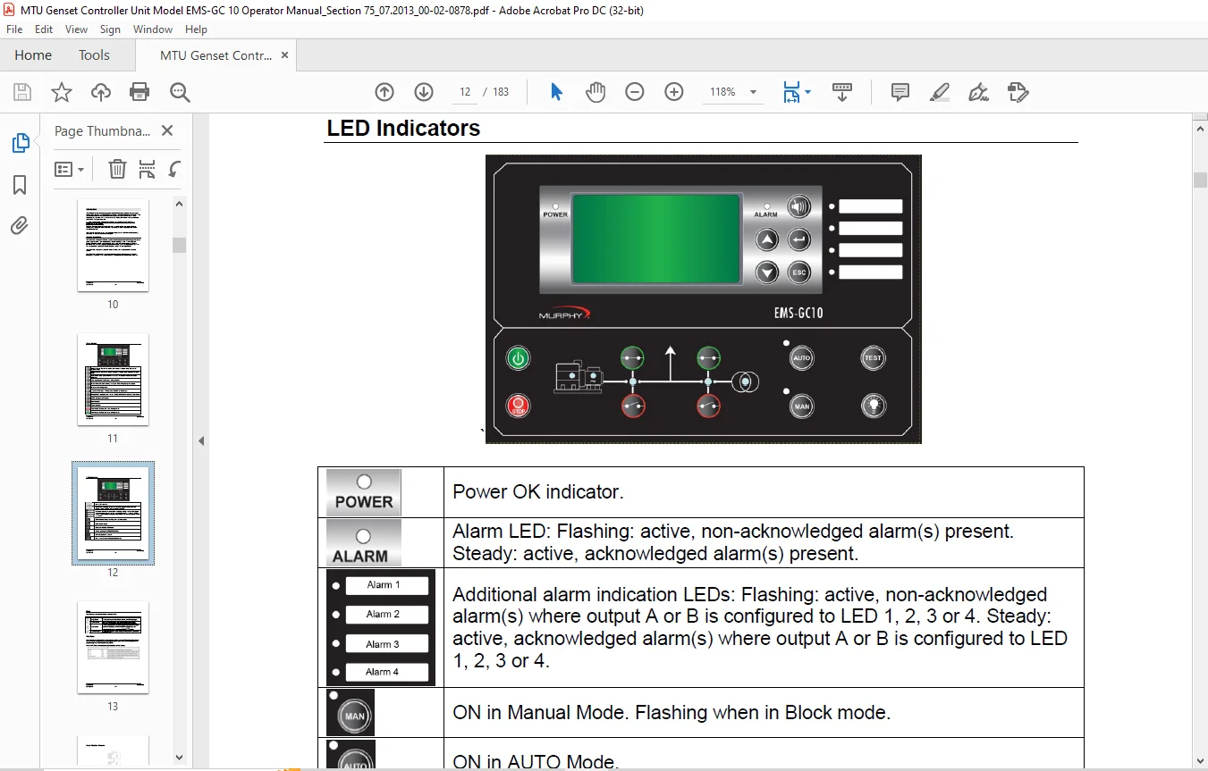
- This Operator’s Manual includes general product information, display readings, push-button, LED functions, alarm handling descriptions, and presentation of the log list.
- This manual is intended to help optimize the operator’s daily use. On the basis of this document, the operator will be able to carry out simple procedures such as start/stop and control of the generator set.
Reference Point:
As a Reference point: Please note that the “U” symbol is also used as an indication for the voltage.
EMS-GC10 Features:
- EMS-GC10 delivers field-adjustable operating parameters but may require further configuration using the Utility Software.
- It can support both mechanical and J1939 electronic engines.
- The EMS-GC10 is ideal for use with a remote modem or in a SCADA system offering Modbus® RTU protocol on the RS485 port.
Product Description:
- The EMS-GC10 Genset Controller provides flexible control and monitoring for industrial genset applications. Typical applications include backup power, power supply for remote locations without a connection to the power grid, and mobile power for remote locations.
- The controller supports programmable logic, up to 40 expressions, and can be configured for specific predefined functions unique to your application.
- The EMS-GC10 supports Automatic Mains Failure (AMF) and generator breaker control.
- The EMS-GC10 offers field-adjustable operating parameters that can be changed through the controller or an easy-to-use PC configuration tool called Utility Software.
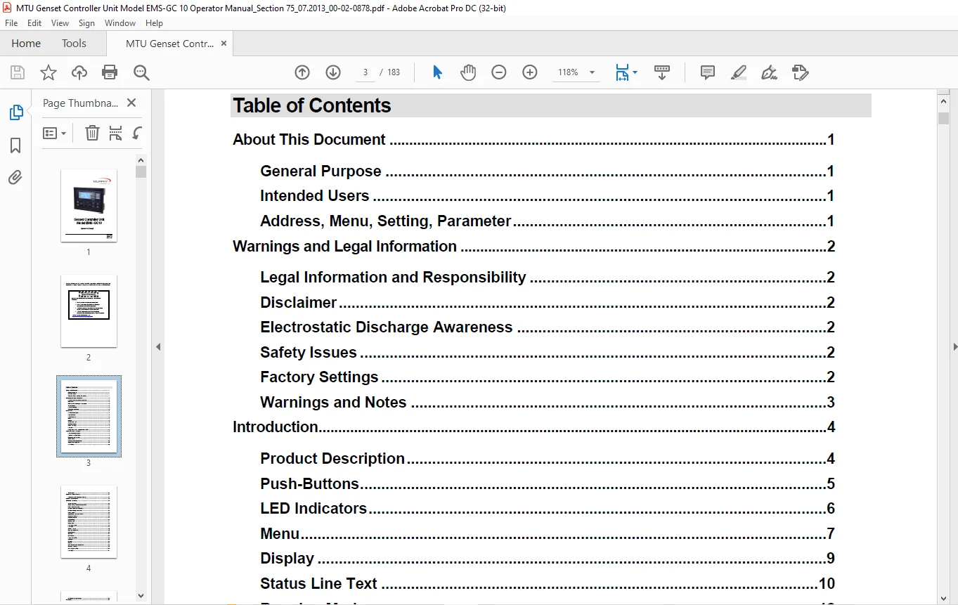
TABLE OF CONTENTS:
MTU MURPHY EMS-GC10 Genset Controller Unit Operator’s Manual PDF DOWNLOAD
Table of Contents...............................................................................................................  3
About This Document.............................................................................................................  7
	General Purpose.............................................................................................................  7
	Intended Users..............................................................................................................  7
	Address, Menu, Setting, Parameter...........................................................................................  7
Warnings and Legal Information..................................................................................................  8
	Legal Information and Responsibility........................................................................................  8
	Disclaimer..................................................................................................................  8
	Electrostatic Discharge Awareness...........................................................................................  8
	Safety Issues...............................................................................................................  8
	Factory Settings............................................................................................................  8
	Warnings and Notes..........................................................................................................  9
		Notes...................................................................................................................  9
		Warnings................................................................................................................  9
Introduction.................................................................................................................... 10
	Product Description......................................................................................................... 10
	Push-Buttons................................................................................................................ 11
	LED Indicators.............................................................................................................. 12
	Menu........................................................................................................................ 13
		View Menu............................................................................................................... 13
		Menu Structure Diagram.................................................................................................. 14
	Display..................................................................................................................... 15
	Status Line Text............................................................................................................ 16
	Running Modes............................................................................................................... 18
	Alarm and Logs.............................................................................................................. 18
	Log List.................................................................................................................... 19
	Parameters—Only Available With USW.......................................................................................... 19
General Product Information..................................................................................................... 21
	Functional Descriptions..................................................................................................... 21
		Standard Functions...................................................................................................... 21
		Operation Modes......................................................................................................... 21
		Engine Control.......................................................................................................... 21
		Generator Protection (ANSI)............................................................................................. 21
		Busbar Protection (ANSI)................................................................................................ 21
		Display................................................................................................................. 22
		M-Logic................................................................................................................. 22
	Terminal Strip Overview..................................................................................................... 22
		Reference to Installation Instructions.................................................................................. 22
	Measurement Systems......................................................................................................... 22
		Single Phase System..................................................................................................... 23
		Split Phase System...................................................................................................... 23
	Applications................................................................................................................ 24
		Applications and Genset Modes........................................................................................... 24
		AMF (No Back Synchronization)........................................................................................... 24
		Island Operation........................................................................................................ 25
		Load Takeover........................................................................................................... 25
	Running Mode Description.................................................................................................... 26
		Manual Mode............................................................................................................. 26
		Test mode............................................................................................................... 27
		Simple Test............................................................................................................. 27
		Full Test............................................................................................................... 27
		Block Mode.............................................................................................................. 28
	Single-Line Diagrams........................................................................................................ 29
		Application Illustration................................................................................................ 29
		Automatic Mains Failure (AMF)........................................................................................... 29
		Island Operation........................................................................................................ 30
		Load Takeover........................................................................................................... 30
	Flowcharts.................................................................................................................. 31
		Mode Shift.............................................................................................................. 32
		MB Open Sequence........................................................................................................ 33
		GB Open Sequence........................................................................................................ 34
		Stop Sequence........................................................................................................... 35
		Start Sequence.......................................................................................................... 36
		MB Close Sequence....................................................................................................... 37
		GB Close Sequence....................................................................................................... 38
		Load Takeover (LTO)..................................................................................................... 39
		Island Operation........................................................................................................ 40
		Automatic Mains Failure (AMF)........................................................................................... 41
		Test Sequence........................................................................................................... 42
	Sequences................................................................................................................... 43
		Start Sequence.......................................................................................................... 44
		Start Sequence Conditions............................................................................................... 45
		Running Feedback........................................................................................................ 46
		Stop Sequence........................................................................................................... 48
		Breaker Sequences....................................................................................................... 50
		AMF Timers.............................................................................................................. 51
Display and Menu Structure...................................................................................................... 53
	Passwords and Parameter Access.............................................................................................. 53
		Passwords............................................................................................................... 53
		Parameter Access........................................................................................................ 55
Engine Communication............................................................................................................ 55
	EMS-GC10 Unit and Engine Controller......................................................................................... 55
Additional Functions............................................................................................................ 56
	Start Functions............................................................................................................. 56
		Digital Feedbacks....................................................................................................... 57
		Analog Tach Feedback.................................................................................................... 58
		Oil Pressure............................................................................................................ 59
	Mains Voltage Unbalance Detection........................................................................................... 60
	Phase Sequence Error........................................................................................................ 60
		Description of Phase Sequence Error..................................................................................... 60
	Breaker Types and Feedback.................................................................................................. 60
		Breaker Types........................................................................................................... 60
		Breaker Feedback........................................................................................................ 61
	Breaker Spring Load Time.................................................................................................... 61
		Island Mode Condition................................................................................................... 63
	Alarm Inhibit............................................................................................................... 64
		Run Status (parameter 6160)............................................................................................. 67
	Digital Mains Breaker Control............................................................................................... 68
	Command Timers.............................................................................................................. 69
	Running Output.............................................................................................................. 70
	Idle Running................................................................................................................ 71
		Description............................................................................................................. 71
		Examples................................................................................................................ 72
		Inhibit................................................................................................................. 73
		Running Signal.......................................................................................................... 73
		Idle speed flowcharts................................................................................................... 73
		Start................................................................................................................... 74
		Engine Heater........................................................................................................... 76
		Engine Heater Alarm..................................................................................................... 76
	Battery Test................................................................................................................ 77
		Input Configuration..................................................................................................... 78
		Auto Configuration...................................................................................................... 78
		Ventilation............................................................................................................. 79
		Max. Ventilation Alarm.................................................................................................. 79
	Not in Auto................................................................................................................. 79
	Fuel Pump Logic............................................................................................................. 80
		Full to Fuel Fill Check................................................................................................. 81
	Fail Class.................................................................................................................. 81
		Engine Running.......................................................................................................... 82
		Engine Stopped.......................................................................................................... 82
		Fail Class Configuration................................................................................................ 83
	Service Timers.............................................................................................................. 84
	Wire Fail Detection......................................................................................................... 85
	Digital Inputs.............................................................................................................. 86
		Functional Description—Input............................................................................................ 87
	Outputs..................................................................................................................... 90
		Functional Description—Output........................................................................................... 91
	Multi-Inputs................................................................................................................ 92
		4-20 mA................................................................................................................. 92
		RMI (Analog) Inputs..................................................................................................... 92
		RMI Oil................................................................................................................. 93
		RMI Water............................................................................................................... 94
		RMI Fuel................................................................................................................ 95
		Illustration of Configurable Inputs..................................................................................... 96
		Configuration........................................................................................................... 96
		Scaling Of 4-20 Ma Inputs............................................................................................... 97
		Binary.................................................................................................................. 99
	Text in Status Line.........................................................................................................100
	Counters....................................................................................................................102
	M-Logic.....................................................................................................................102
	Buzzer......................................................................................................................103
		GSM Communication.......................................................................................................103
	USW Remote Communication....................................................................................................104
	Nominal Settings............................................................................................................105
		How to Change the Nominal Settings......................................................................................105
	AC Voltage Scaling..........................................................................................................106
	Fan Logic...................................................................................................................107
		Fan Parameters..........................................................................................................107
		Input for Fan Control...................................................................................................108
		Fan Start/Stop..........................................................................................................108
		Fan Output..............................................................................................................109
		Fan Start Delay.........................................................................................................109
		Fan Failure.............................................................................................................110
		Fan Priority (Running Hours)............................................................................................110
		Fan Priority Update.....................................................................................................111
	Differential Measurement....................................................................................................112
Protections.....................................................................................................................113
	General.....................................................................................................................113
		Phase-Neutral Voltage Trip..............................................................................................113
Appendix I —Can Bus Engine Interface Communication..............................................................................115
	Terminal Description for EMS-GC10...........................................................................................115
	Modbus Communication........................................................................................................115
	Terminals...................................................................................................................115
	Principle Diagram...........................................................................................................115
Functional Description..........................................................................................................116
	Electronic Control Module (ECM).............................................................................................116
		ECM.....................................................................................................................116
	Engine Types................................................................................................................116
	Communication System........................................................................................................117
	EIC Unit....................................................................................................................117
	Common for all Alarm Functions..............................................................................................117
	J1939 Measurement Table.....................................................................................................117
		The display values corresponding to the engine communication have a description beginning with “EIC”. Error Messages....117
		Object Selection, J1939.................................................................................................118
		For the Iveco Vector 8 Type Only:.......................................................................................120
		For the MTU Smart Connect Type Only:....................................................................................120
	Showing Engine Values in Display............................................................................................120
		Configuration of the User View..........................................................................................121
		Activation of Auto Views................................................................................................121
	Verification of J1939 Objects...............................................................................................121
	Displaying Alarms - J1939 DM1/DM2, Scania KWP2000, Caterpillar/Perkins......................................................122
		J1939...................................................................................................................122
		Scania KWP 2000.........................................................................................................123
		Caterpillar/Perkins.....................................................................................................123
	Displaying Alarms - EMS-GC10................................................................................................124
		J1939...................................................................................................................124
		Scania KWP 2000.........................................................................................................124
		Caterpillar/Perkins.....................................................................................................125
	Control Commands Sent to the Engine.........................................................................................125
		EIC 50 Hz – 60 Hz Switch................................................................................................126
		EIC Droop...............................................................................................................126
		EIC Inhibit.............................................................................................................127
		EIC Idle................................................................................................................127
Specific Engine Type Descriptions...............................................................................................128
	About Type Descriptions.....................................................................................................128
	Caterpillar/Perkins (J1939).................................................................................................128
		Warnings and Shutdowns..................................................................................................128
		Write Commands to Engine Controller.....................................................................................129
	Cummins CM850-CM570 (J1939).................................................................................................129
		Warnings and Shutdowns..................................................................................................129
		Write Commands to Engine Controller.....................................................................................130
		Cummins After Treatment.................................................................................................131
	Detroit Diesel DDEC (J1939).................................................................................................132
		Warnings and Shutdowns..................................................................................................132
		Write Commands to Engine Controller.....................................................................................132
	Deutz EMR 2 – EMR 3 (J1939).................................................................................................132
		Warnings and Shutdowns..................................................................................................132
		Write Commands to Engine Controller.....................................................................................133
	Generic J1939 (J1939).......................................................................................................133
		Warnings and Shutdowns..................................................................................................133
		Write Commands to Engine Controller.....................................................................................133
	Iveco (J1939)...............................................................................................................134
		Warnings and Shutdowns..................................................................................................134
		Write Commands to Engine Controller.....................................................................................134
	John Deere JDEC (1939)......................................................................................................135
		Warnings and Shutdowns..................................................................................................135
		Write Commands to Engine Controller.....................................................................................135
	MTU J1939 Smart Connect.....................................................................................................136
		Smart Connect...........................................................................................................136
		Warnings and Shutdowns..................................................................................................136
		Write Commands to Engine Controller.....................................................................................136
	MTU ADEC (CANopen)..........................................................................................................137
		Display Readings........................................................................................................137
		Warning.................................................................................................................138
		Shutdown................................................................................................................139
		Write Commands to Engine Controller.....................................................................................139
	MTU MDEC Module 302/303 (MTU)...............................................................................................140
		Alarms..................................................................................................................140
		Write Commands to Engine Controller.....................................................................................141
	Scania EMS (J1939)..........................................................................................................141
		Warning/Shutdown........................................................................................................141
		Write Commands to Engine Controller.....................................................................................141
	Scania EMS 2 S6 (J1939).....................................................................................................141
		Scania EMS 2 S6 (J1939).................................................................................................141
		Warnings and Shutdowns (DNL2 Alarms)....................................................................................141
		Error Log...............................................................................................................142
		Write Commands to Engine Controller.....................................................................................143
		Control.................................................................................................................143
	Volvo Penta EMS (J1939).....................................................................................................144
		Warnings and Shutdowns..................................................................................................144
		Write Commands to Engine Controller.....................................................................................144
	Volvo Penta EMS 2 (J1939)...................................................................................................145
		Warnings and Shutdowns..................................................................................................145
		Write Commands to Engine Controller.....................................................................................145
		Readable States - Preheat and Running...................................................................................145
Modbus Communication............................................................................................................146
	Additional Information......................................................................................................146
	Readings....................................................................................................................146
		Analog Values...........................................................................................................146
		Diagnostic Codes........................................................................................................149
Alarms..........................................................................................................................153
	Caterpillar/Perkins.........................................................................................................153
	Cummins.....................................................................................................................154
	DDEC – Detroit Engines......................................................................................................155
	EMR 2 – EMR 3 - Deutz Engines...............................................................................................156
	Generic J1939...............................................................................................................157
	Iveco.......................................................................................................................158
		JDEC – John Deere Engines...............................................................................................159
	Mtu Smart Connect...........................................................................................................160
	MTU ADEC....................................................................................................................161
	MTU MDEC Series - 2000/4000 - Module 302 & 303..............................................................................163
	Scania......................................................................................................................164
	Volvo Penta.................................................................................................................166
Appendix II —M-Logic............................................................................................................167
	Introduction to M-Logic.....................................................................................................167
Configuration...................................................................................................................168
	Starting the M-Logic........................................................................................................168
		Read/Write and Save/Open................................................................................................169
	Basic Functions.............................................................................................................170
		Events A, B, and C......................................................................................................171
		Operators...............................................................................................................172
		Enable the Rule.........................................................................................................172
		Output..................................................................................................................172
	Definitions.................................................................................................................173
	Examples....................................................................................................................174
		Virtual Events..........................................................................................................174
		Set/Reset Function......................................................................................................174
		Power Up In a Specific Mode.............................................................................................175
		Flip-Flop Function......................................................................................................175
List of Events and Commands.....................................................................................................176
	Operators...................................................................................................................179
	Outputs.....................................................................................................................179
PLEASE NOTE:
- This is the same manual used by the dealers to diagnose and troubleshoot your vehicle
- You will be directed to the download page as soon as the purchase is completed. The whole payment and downloading process will take anywhere between 2-5 minutes
- Need any other service / repair / parts manual, please feel free to contact [email protected] . We still have 50,000 manuals unlisted
G.P