Description
MTU Diesel Engine 20V4000Gx2 Operating Instructions Manual M015565-03E PDF DOWNLOAD
FILE DETAILS:
MTU Diesel Engine 20V4000Gx2 Operating Instructions Manual M015565-03E PDF DOWNLOAD
Language : English
Pages : 143
Downloadable : Yes
File Type : PDF
IMAGES PREVIEW OF THE MANUAL:


TABLE OF CONTENTS:
MTU Diesel Engine 20V4000Gx2 Operating Instructions Manual M015565-03E PDF DOWNLOAD
Operating Instructions 1
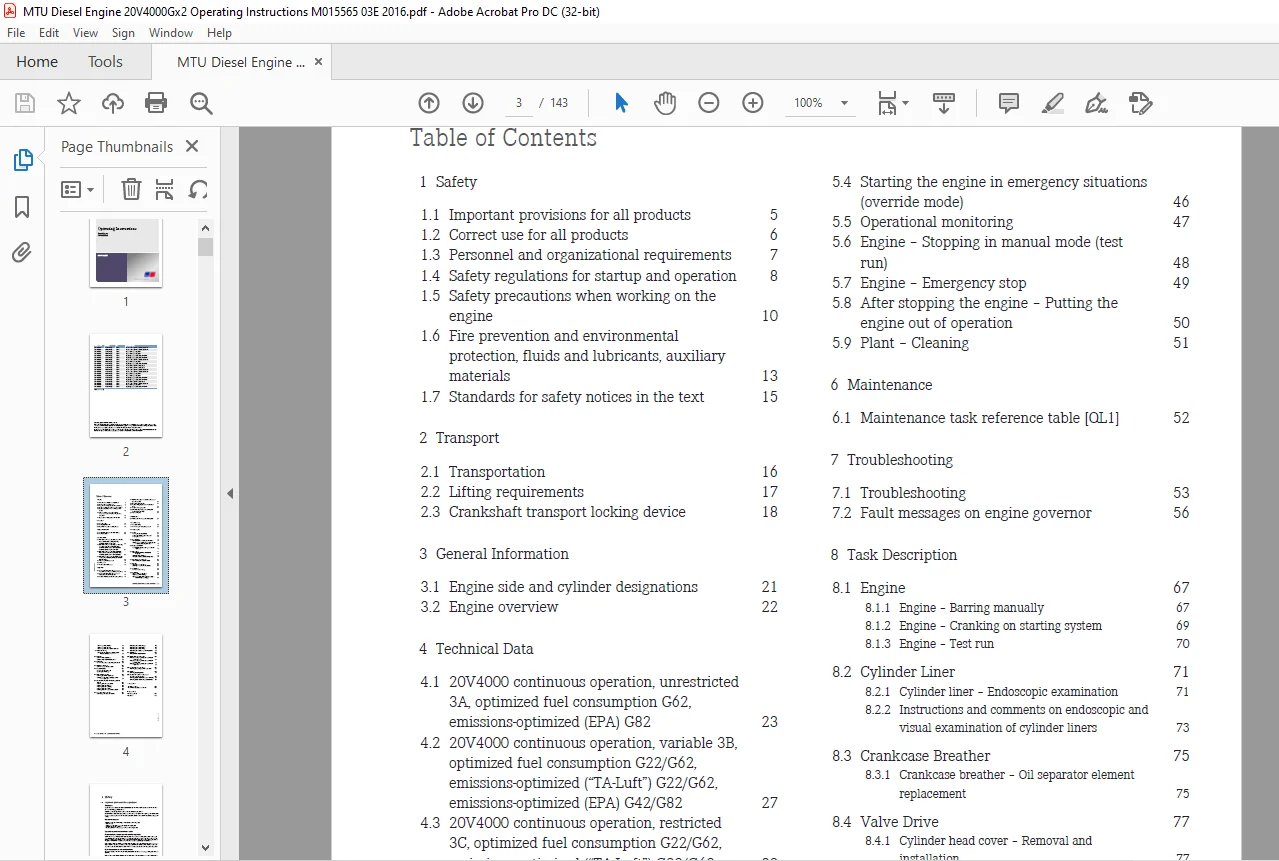
Table of Contents 3
1 Safety 5
11 Important provisions for all products 5
12 Correct use for all products 6
13 Personnel and organizational requirements 7
14 Safety regulations for startup and operation 8
15 Safety precautions when working on the engine 10
16 Fire prevention and environmental protection, fluids and lubricants, auxiliary materials 13
17 Standards for safety notices in the text 15
2 Transport 16
21 Transportation 16
22 Lifting requirements 17
23 Crankshaft transport locking device 18
3 General Information 21
31 Engine side and cylinder designations 21
32 Engine overview 22
4 Technical Data 23
41 20V4000 continuous operation, unrestricted 3A, optimized fuel consumption G62, emissions-optimized (EPA) G82 23
42 20V4000 continuous operation, variable 3B, optimized fuel consumption G22/G62, emissions-optimized (“TA-Luft”) G22/G62, emissions-optimized (EPA) G42/G82 27
43 20V4000 continuous operation, restricted 3C, optimized fuel consumption G22/G62, emissions-optimized (“TA-Luft”) G22/G62 32
44 20V4000 standby power 3D, optimized fuel consumption G22/G62, emissions-optimized (EPA) G42/G82 36
45 Final compression pressure 40
46 Firing order 41
47 Main engine dimensions 42
5 Operation 43
51 Putting the engine into operation after extended out-of-service periods (>3 months) 43
52 Putting the engine into operation after scheduled out-of-service-period 44
53 Engine – Starting in manual mode (test run) 45
54 Starting the engine in emergency situations (override mode) 46
55 Operational monitoring 47
56 Engine – Stopping in manual mode (test run) 48
57 Engine – Emergency stop 49
58 After stopping the engine – Putting the engine out of operation 50
59 Plant – Cleaning 51
6 Maintenance 52
61 Maintenance task reference table [QL1] 52
7 Troubleshooting 53
71 Troubleshooting 53
72 Fault messages on engine governor 56
8 Task Description 67
81 Engine 67
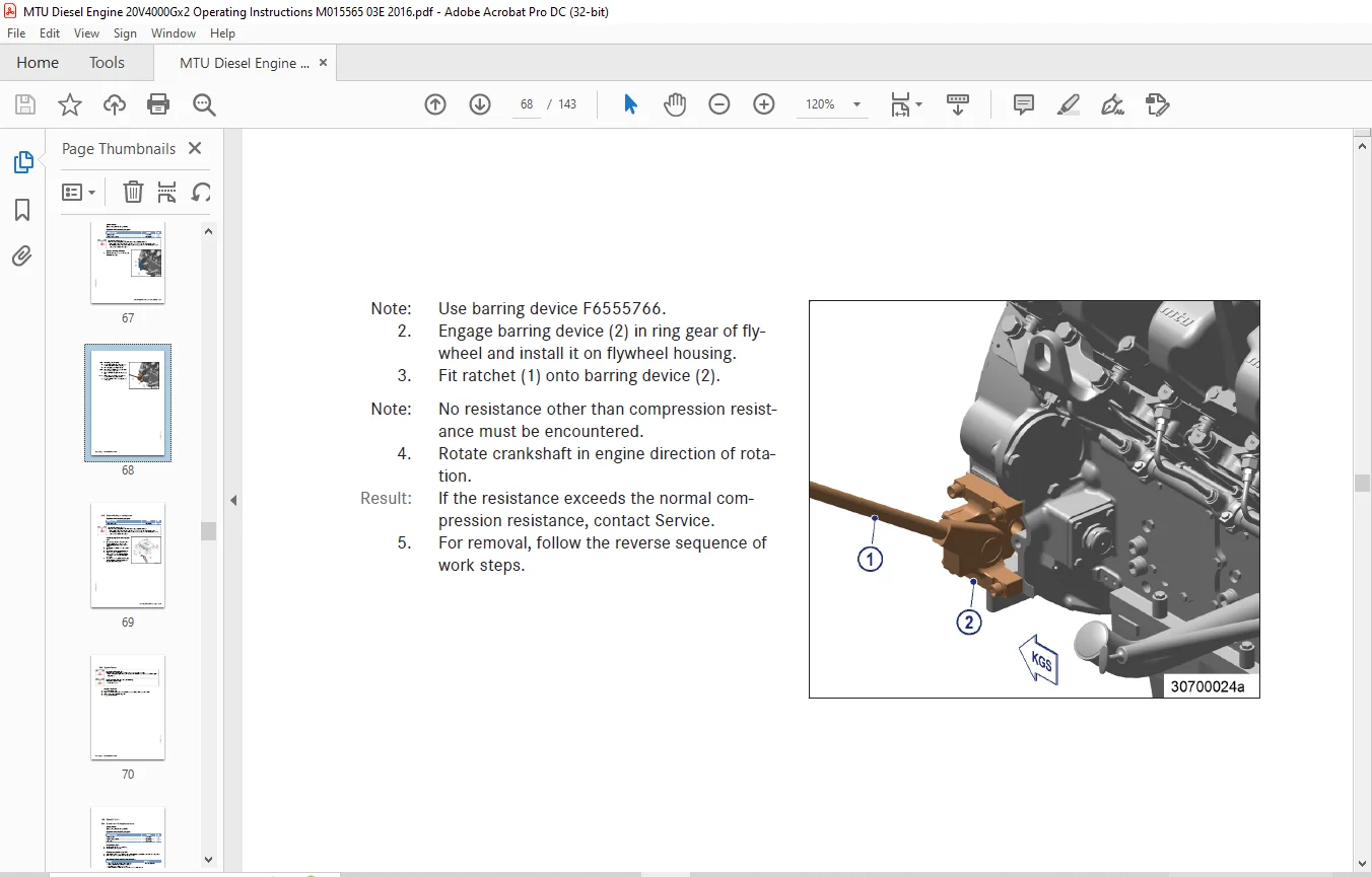
811 Engine – Barring manually 67
812 Engine – Cranking on starting system 69
813 Engine – Test run 70
82 Cylinder Liner 71
821 Cylinder liner – Endoscopic examination 71
822 Instructions and comments on endoscopic and visual examination of cylinder liners 73
83 Crankcase Breather 75
831 Crankcase breather – Oil separator element replacement 75
84 Valve Drive 77
841 Cylinder head cover – Removal and installation 77
842 Valve gear – Lubrication 78
843 Valve clearance – Check and adjustment 79
85 Injection Pump / HP Pump 84
851 HP fuel pump – Relief bore check 84
86 Injector 85
861 Injector – Replacement 85
862 Injector – Removal and installation 86
87 Fuel System 91
871 Fuel system – Venting 91
88 Fuel Filter 92
881 Fuel filter – Replacement 92
882 Fuel prefilter – Cleaning 93
883 Fuel prefilter – Differential pressure gage check and adjustment of gage 94
884 Fuel prefilter – Draining 95
885 Fuel prefilter – Flushing 96
886 Fuel prefilter – Filter element replacement 98
89 Charge-Air Cooling100
891 Intercooler – Check water drain for coolant leakage and absence of restrictions100
810 Air Filter101
8101 Air filter ‒ Replacement101
8102 Air filter – Removal and installation102
811 Air Intake103
8111 Service indicator – Signal ring position check103
812 Starting Equipment104
8121 Air starter – Manual operation104
813 Lube Oil System105
8131 Engine oil – Level check105
8132 Engine oil – Change106
814 Oil Filtration / Cooling108
8141 Engine oil filter – Replacement108
8142 Centrifugal oil filter – Cleaning and filter-sleeve replacement109
815 Coolant Circuit, General, High-Temperature Circuit111
8151 Engine coolant – Level check111
8152 Engine coolant – Change112
8153 Engine coolant – Draining113
8154 Engine coolant – Filling114
8155 Engine coolant pump – Relief bore check116
816 Low-Temperature Circuit117
8161 Charge-air coolant – Level check117
8162 Charge-air coolant – Change118
8163 Charge-air coolant draining119
8164 Charge-air coolant – Filling 120
8165 Charge-air coolant pump – Relief bore check122
817 Belt Drive123
8171 Drive belt – Condition check123
818 Battery-Charging Generator124
8181 Battery-charging generator drive – Drive belt tension adjustment124
8182 Battery-charging generator drive – Drive belt condition check125
8183 Battery-charging generator drive – Drive belt replacement126
819 Engine Mounting / Support127
8191 Engine mounting – Resilient mount check127
820 Cabling128
8201 Engine cabling – Check128
821 Accessories for (Electronic) Engine Governor / Control System 129
8211 Engine Control Unit and connectors – Cleaning129
8212 Engine Control Unit – Plug connection check130
9 Appendix A131
91 Abbreviations131
92 MTU Contact/Service Partners134
10 Appendix B135
101 Special Tools135
102 Index141
Need help? Contact: [email protected]
https://vimeo.com/858578080?share=copy
DESCRIPTION:
MTU Diesel Engine 20V4000Gx2 Operating Instructions Manual M015565-03E PDF DOWNLOAD
SAFETY INSTRUCTIONS:
Important Provisions for All Product
Nameplate
The product is identified by a nameplate, model designation, or serial number and must match the information on the title page of this manual. The nameplate, model designation, or serial number can be found on the product.
All EU-certified engines delivered by MTU come with a second nameplate. When operating the machine in the EU: The second nameplate must be affixed in a prominent position as described in the accompanying specifications.
General Information
This product may pose a risk of injury or damage in the following cases:
- Incorrect use
- Operation, maintenance, and repair by unqualified personnel
- Modifications or conversions
- Noncompliance with the safety instructions and warning notices
Emission Regulations and Emission Labels
Responsibility for Compliance with Emission Regulations
Modification or removal of any mechanical/electronic components or the installation of additional components, including the execution of calibration processes that might affect the emission characteristics of the product, are prohibited by emission regulations. Emission control units/systems may only be maintained, exchanged, or repaired if the components used for this purpose are approved by the manufacturer.
Noncompliance with these regulations will invalidate the design type approval issued by the emissions regulation authorities. The manufacturer does not accept any liability for violations of the emission regulations.
The maintenance schedules of the manufacturer must be observed over the entire life cycle of the product.
Replacing Components with Emission Labels
On all MTU engines fitted with emission labels, these labels must remain on the engine throughout its operational life.
Engines used exclusively in land-based, military applications other than by US government agencies are excepted from this proviso.
Please note the following when replacing components with emission labels:
The relevant emission labels must be affixed to the spare part.
Do not transfer the emission labels from the replaced part to the spare part.
Remove the emission labels from the replaced part and destroy them.
PLEASE NOTE:
- This is the same manual used by the dealers to diagnose and troubleshoot your vehicle
- You will be directed to the download page as soon as the purchase is completed. The whole payment and downloading process will take anywhere between 2-5 minutes
- Need any other service / repair / parts manual, please feel free to contact [email protected] . We still have 50,000 manuals unlisted
G.P