Trusted Business
Verified & Licensed
Virus Free Files
100% Safe Downloads
Secure Payment
SSL Protected
Instant Delivery
Available Immediately
Moto Guzzi V 1000 SP G5 Workshop Manual – PDF DOWNLOAD
$25.95
Moto Guzzi V 1000 SP G5 Workshop Manual – PDF DOWNLOAD
Instant PDF Download
Available immediately
Save to Your Device
Download & keep forever
Antivirus Scanned
100% virus-free
Trusted Worldwide
175,000+ customers
Description
Moto Guzzi V 1000 SP G5 Workshop Manual – PDF DOWNLOAD
FILE DETAILS:
Moto Guzzi V 1000 SP G5 Workshop Manual – PDF DOWNLOAD
Language : English
Pages : 154
Downloadable : Yes
File Type : PDF
IMAGES PREVIEW OF THE MANUAL:
DESCRIPTION:
Moto Guzzi V 1000 SP G5 Workshop Manual – PDF DOWNLOAD
- Purpose of this manual is to give the necessary instructions for overhauling and carrying out repairs in a rational way.
- All data herein contained are meant to give a general knowledge of the main checking operations to be done when overhauling the different component groups.
- To this end, the manual contains many illustrations. drawings, diagrams. and tables to assist you in the stripping, checking. and assembling operations.
- This manual will also be a guidance for anybody who wishes to familiarize with the manufacturing characteristics of the various component parts of the V 1000 G 5 and 1000 SP models.
- The knowledge of these will be an essential factor for performing a good job.
- All illustrations and descriptions in this manual should be intended as indicative only as the Manufacturer reserves itself the right to introduce at any time and without prior advice any modification it may deem useful for a better performance or for any other reason of a constructional or commercial nature.
TABLE OF CONTENTS:
Moto Guzzi V 1000 SP G5 Workshop Manual – PDF DOWNLOAD
1. IDENTIFICATION DATA
1.1 Spare parts
1.2 Warranty
1.2 Warranty
2. MAIN FEATURES
2.1 Model V 1000 G 5
2.2 Model 1000 SP
2.2 Model 1000 SP
3. CONTROLS AND ACCESSORIES
3.1 Model V 1000 G 5
3.2 Model 1000 SP
3.2 Model 1000 SP
4. LUBRICATIONS
4.1 Engine lubrication
4.2 Replacing the oil filter cartridge and cleaning the wire gauze filter
4.3 Lubricating the gearbox
4.4 Lubricating the rear drive box
4.5 Fork lubrication
4.6 Lubrication of steering bearings and swing arm
4.2 Replacing the oil filter cartridge and cleaning the wire gauze filter
4.3 Lubricating the gearbox
4.4 Lubricating the rear drive box
4.5 Fork lubrication
4.6 Lubrication of steering bearings and swing arm
5. INSTRUMENTS AND CONTROLS
5.1 Panel board – model V 1000 G 5
5.2 Ignition key – model V 1000 G 5
5.3 Panel board – model 1000 SP
5.4 Light switches
5.5 Horn, turn lights, and flashing light buttons
5.6 Engine starting and emergency stop button
5.7 Easy starter lever
5.8 Throttle control grip
5.9 Clutch control lever
5.10 Right front brake control lever
5.11 Twin brake control, front left and rear
5.12 Gearshift pedal
5.13 Fuel filter cap
5.14 Fuel level
5.15 Fuel tap – V 1000 G 5 model
5.16 Fuel tap – V 1000 SP model
5.17 Electrovalve – V 1000 G 5
5.18 Terminal block with fuses
5.19 Steering
5.20 Side stand – V 1000 G 5 model
5.21 Side stand – 1000 SP model
5.22 Steering damper – 1000 SP model
6. MAINTENANCE AND ADJUSTMENTS
6.1 Adjusting the clutch lever play
6.2 Adjusting the right front brake lever
6.3 Adjusting the front left and rear brake pedal
6.4 Adjusting the steering
6.5 Adjusting the rear suspension
6.6 Adjusting the throttle control grip
6.7 Adjusting the rear wheel spokes – V 1000 G 5
6.8 Adjusting the headlight beam – V 1000 G 5
6.9 Adjusting the headlight beam – 1000 SP
6.10 Rocker clearance
6.11 Adjusting the double contact breaker
6.12 Maintenance
6.13 Cleaning the windshield
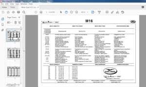
7. LUBRICATION AND MAINTENANCE CHART
8. TORQUE WRENCH SETTINGS
9. SPECIAL TOOLS FOR REPAIR SHOPS
10. REMOVING THE ENGINE-GEARBOX UNIT FROM THE FRAME
10.1 Introduction
10.2 Removal
10.2 Removal
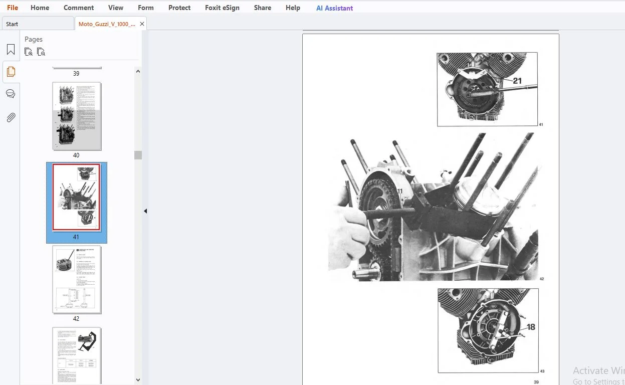
11. STRIPPING THE ENGINE
12. OVERHAULING AND CHECKING OPERATIONS
12.1 Rocker covers
12.2 Stripping the cylinder heads
12.3 Cylinder heads
12.4 Valve guides
12.5 Valve seats
12.6 Valves
12.7 Checking the inlet and exhaust valve opening
12.8 Inspecting the valve springs
12.9 Refitting the valve springs assembly on heads
12.10 Assembling the cylinder barrels
12.11 Refitting the cylinder heads on the cylinders
12.12 Cylinder barrels
12.13 Piston rings and oil scraper
12.14 Connecting rods
12.15 Fitting the con-rods on crankshaft
12.16 Crankshaft
12.17 Checking the weight for engine balancing
12.18 Fitting the flywheel on the crankshaft
12.19 Drive side flange complete with main journal
12.20 Seal for flange, drive side
12.21 Fitting the flange c/w journal in crankcase, drive side
12.22 Assembling the seal on timing cover
12.23 Crankcase
12.24 Checking oil leakages from the crankcase
13. TIMING
13.1 Timing data
13.2 Diameter of camshaft bearings in their housings in crankcase
13.3 Tappet-guide in crankcase – coupling data
13.4 Assembling the crankshaft assembly, gears with chain on shaft, engine-timing, oil pump
13.5 How to change the chain and/or gear with engine assembled on the frame
13.6 Valve timing
13.2 Diameter of camshaft bearings in their housings in crankcase
13.3 Tappet-guide in crankcase – coupling data
13.4 Assembling the crankshaft assembly, gears with chain on shaft, engine-timing, oil pump
13.5 How to change the chain and/or gear with engine assembled on the frame
13.6 Valve timing
14. ENGINE LUBRICATION
14.1 Oil delivery pump
14.2 Oil sump
14.3 Replacing the oil filter cartridge
14.4 Wire gauze filter
14.5 Oil pressure relief valve
14.6 Oil breather valve on the crankcase piping to the re-cycling, oil over on filter assy
14.7 Oil pressure solenoid
14.8 Checking the oil pressure with engine on the bike
14.2 Oil sump
14.3 Replacing the oil filter cartridge
14.4 Wire gauze filter
14.5 Oil pressure relief valve
14.6 Oil breather valve on the crankcase piping to the re-cycling, oil over on filter assy
14.7 Oil pressure solenoid
14.8 Checking the oil pressure with engine on the bike
15. CARBURATION
15.1 Carburettors
15.2 Float levelling
15.3 Adjusting the carburation and idling speed
15.4 Checking carburation with a vacuometer
15.5 Carburettor components
15.6 Replacing the air filter cartridge on assembled engine
15.2 Float levelling
15.3 Adjusting the carburation and idling speed
15.4 Checking carburation with a vacuometer
15.5 Carburettor components
15.6 Replacing the air filter cartridge on assembled engine
16. CLUTCH
16.1 Removing the clutch assembly
16.2 Inspections
16.3 Assembling the clutch on flywheel
16.2 Inspections
16.3 Assembling the clutch on flywheel
17. GEARBOX
17.1 Stripping the gearbox
17.2 Checking and overhauling the gearbox components
17.3 Assembling the gearbox on the bench
17.2 Checking and overhauling the gearbox components
17.3 Assembling the gearbox on the bench
18. REAR DRIVE
18.1 Removing the gear drive box
18.2 Inspections and overhauls
18.3 Re-assembly
18.2 Inspections and overhauls
18.3 Re-assembly
19. FRAME
20. REAR SUSPENSION
21. FRONT SUSPENSION AND STEERING
22. SWINGING ARM
22.1 Inspection
22.2 Removing the bearings from the swing fork
22.3 Pressing the outer races on the swing arm taper bearings
22.4 Pressing the bearings into the R/H arm of the swing fork
22.5 Adjusting the swing arm play
22.2 Removing the bearings from the swing fork
22.3 Pressing the outer races on the swing arm taper bearings
22.4 Pressing the bearings into the R/H arm of the swing fork
22.5 Adjusting the swing arm play
23. WHEELS
23.1 Removing the front wheel – V 1000 G 5 model
23.2 Removing the front wheel – 1000 SP model
23.3 Rear wheel – V 1000 G 5 model
23.4 Rear wheel – 1000 SP model
23.5 Tires
23.6 Tensioning the wheel spokes – V 1000 G 5
23.7 Wheel balancing
23.8 Tire removal and refitting – V 1000 G 5
23.9 Tire removal and refitting – 1000 SP
23.10 Checking and overhauling the braking circuits
23.11 Master cylinder for right front brake
23.12 Master cylinder for left front and rear brakes
23.13 Brake caliper for front brakes (model V 1000 G 5) and rear brakes (model 1000 SP)
23.14 Front brake caliper for 1000 SP model
23.15 Brake pads
23.16 Pipes
23.17 Braking discs
23.18 Braking circuit faults
23.19 Recommendations
24. ELECTRICAL EQUIPMENT
24.1 Battery
24.2 Alternator-generator
24.3 Regulator
24.4 Rectifier
24.5 Starter motor
24.6 Ignition system
24.7 Automatic advance
24.8 Capacitors
24.9 Ignition coils
24.10 Spark plugs
24.11 Twin contact breaker
24.12 Assembling the breaker on the crankcase
24.13 Ignition timing
24.14 Checking the ignition advance (static + dynamic) using probe lamp
24.15 Lighting equipment and horns – V 1000 G 5
24.16 Lighting equipment and horns – 1000 SP
25. WIRING DIAGRAM
25.1 Legend – V 1000 G 5 model
25.2 Legend – 1000 SP model
25.2 Legend – 1000 SP model
S.S 20/03/2025