Mitsubishi Forklift FG20S FD20HS FG25S FD25HS FG30S FG30HS Service Manual – PDF DOWNLOAD
Original price was: $76.95.$33.95Current price is: $33.95.
Mitsubishi Forklift FG20S FD20HS FG25S FD25HS FG30S FG30HS Chassis & Mast Service Manual – PDF DOWNLOAD
For use with K25 and S4S Engine Service Manuals.
Pub.No :99729-10100
FG20S CF54-10011-up
FG25S CF54-50011-up
FG30S CF55-10011-up
FD20HS CF50-10011-up
FD25HS CF50-50011-up
FD30HS CF51-10011-up
Description
Mitsubishi Forklift FG20S FD20HS FG25S FD25HS FG30S FG30HS Service Manual – PDF DOWNLOAD
FILE DETAILS:
Mitsubishi Forklift FG20S FD20HS FG25S FD25HS FG30S FG30HS Service Manual – PDF DOWNLOAD
Format: PDF
Language: English
Brand: Mitsubishi
DESCRIPTION:
Mitsubishi Forklift FG20S FD20HS FG25S FD25HS FG30S FG30HS Chassis & Mast Service Manual – PDF DOWNLOAD
For use with K25 and S4S Engine Service Manuals.
Pub.No :99729-10100
FG20S CF54-10011-up
FG25S CF54-50011-up
FG30S CF55-10011-up
FD20HS CF50-10011-up
FD25HS CF50-50011-up
FD30HS CF51-10011-up
FOREWORD :
This service manual is a guide for servicing Mitsubishi forklift trucks. The long productive life of your truck(s) depends on regular and proper servicing, servicing consistent with what you will learn by reading this service manual. Read the respective sections of this manual carefully and familiarize yourself with all of the components before attempting to start a test, repair, or rebuild job. The descriptions, illustrations and specifications contained in this manual are for forklift trucks with serial numbers in effect at the time of printing. Mitsubishi Forklift Trucks reserves the right to change specifications or designs without notice and without incurring obligations. For your convenience the instructions are grouped by systems as an easy reference. For engine servicing, please refer to the applicable engine service manual.
- K25 Gasoline engine
- S4S Diesel engine
SAFETY PRECAUTIONS:
- This service manual contains the proper and safe lubrication and maintenance information recommended by Mitsubishi Forklift Trucks. Please read this service manual carefully and fully understand the procedures before proceeding with any maintenance work. Improper lubrication or maintenance work is dangerous and could result in injury or death.
- Be sure to read this service manual and understand the contents before proceeding with the work. Improper truck operation is dangerous and could result in injury or death. Be sure to familiarize yourself with the systems and components described herein before proceeding with removal or disassembly work. For heavyweight components, BE SURE to check the weight of each component beforehand by referring to this service manual. Also, for safety, use proper lifting equipment for removal/ installation work. Following is a list of basic precautions that should always be observed.
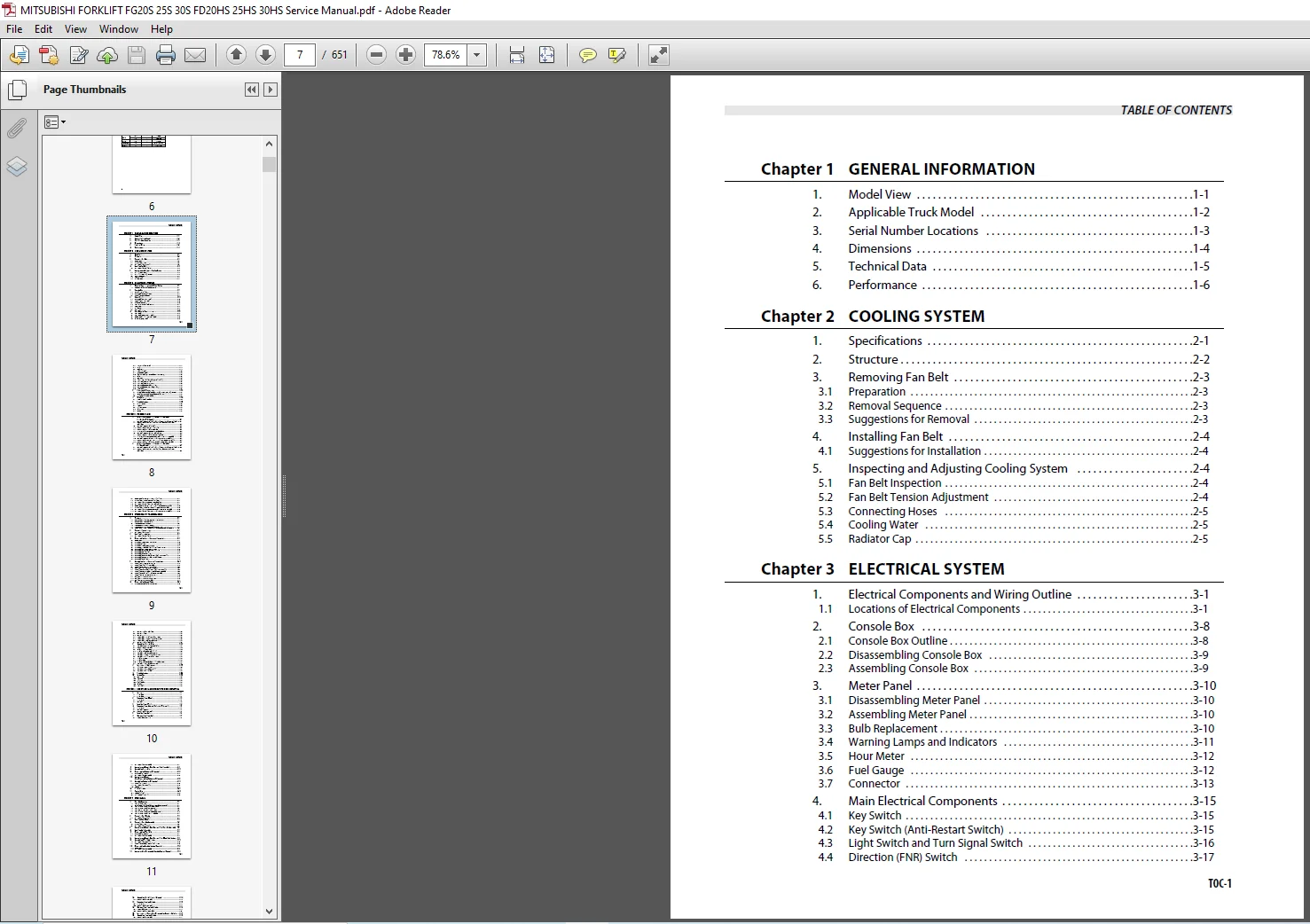
TABLE OF CONTENTS:
Mitsubishi Forklift FG20S FD20HS FG25S FD25HS FG30S FG30HS Service Manual – PDF DOWNLOAD
Chapter 1 GENERAL INFORMATION
1 Model View 1-1
2 Applicable Truck Model 1-2
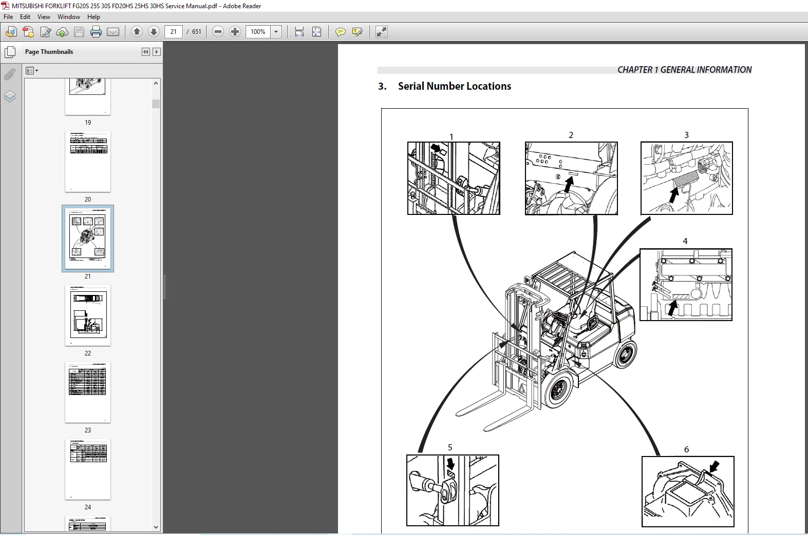
3 Serial Number Locations 1-3
4 Dimensions 1-4
5 Technical Data 1-5
6 Performance 1-6
Chapter 2 COOLING SYSTEM
1 Specifications 2-1
2 Structure 2-2
3 Removing Fan Belt 2-3
3 1 Preparation 2-3
3 2 Removal Sequence 2-3
3 3 Suggestions for Removal 2-3
4 Installing Fan Belt 2-4
4 1 Suggestions for Installation 2-4
5 Inspecting and Adjusting Cooling System 2-4
5 1 Fan Belt Inspection 2-4
5 2 Fan Belt Tension Adjustment 2-4
5 3 Connecting Hoses 2-5
5 4 Cooling Water 2-5
5 5 Radiator Cap 2-5
Chapter 3 ELECTRICAL SYSTEM
1 Electrical Components and Wiring Outline 3-1
1 1 Locations of Electrical Components 3-1
2 Console Box 3-8
2 1 Console Box Outline 3-8
2 2 Disassembling Console Box 3-9
2 3 Assembling Console Box 3-9
3 Meter Panel 3-10
3 1 Disassembling Meter Panel 3-10
3 2 Assembling Meter Panel 3-10
3 3 Bulb Replacement 3-10
3 4 Warning Lamps and Indicators 3-11
3 5 Hour Meter 3-12
3 6 Fuel Gauge 3-12
3 7 Connector 3-13
4 Main Electrical Components 3-15
4 1 Key Switch 3-15
4 2 Key Switch (Anti-Restart Switch) 3-15
4 3 Light Switch and Turn Signal Switch 3-16
4 4 Direction (FNR) Switch 3-17
TABLE OF CONTENTS
TOC-2
4 5 GAS/LPG Select Switch 3-18
4 6 Horn 3-19
4 7 Tank Unit 3-19
4 8 Brake Oil Level 3-20
4 9 Stop Light Switch 3-20
4 10 Thermoswitch (Engine Coolant Temperature) 3-21
4 11 Relay 3-22
4 12 Fuse Box 3-25
4 13 Glow Timer and Glow Relay (Diesel Model) 3-26
4 14 Front Combination Light 3-28
4 15 Front Combination Harness 3-29
4 16 Rear Combination Light (Option) 3-30
4 17 Rear Combination Harness (Option) 3-31
4 18 List of Lights 3-32
5 Battery and Maintenance 3-33
5 1 State of Charge and Electrolyte Specific Gravity (S G ) Adjustment 3-33
5 2 Specific Gravity Reading and State of Charge 3-33
5 3 Precautions for Battery Charging 3-33
6 Wire Color 3-34
6 1 List of Wire Color Codes 3-34
7 Troubleshooting 3-35
7 1 Starter System 3-35
7 2 Gauges 3-35
7 3 Lighting System 3-36
7 4 Alarm Unit 3-37
7 5 Battery 3-37
Chapter 4 POWER TRAIN
1 Installation of Engine and Transmission Assembly
(for Dual Gas/LPG Models) 4-1
1 1 Removal Sequence of Overhead Guard Cover, Air Cleaner, and Others 4-1
1 2 Suggestions for Removing Overhead Guard Cover, Air Cleaner,
and Others 4-2
1 3 Removal Sequence of Controls 4-3
1 4 Suggestions for Removing Controls 4-3
1 5 Suggestions for Installing Controls 4-3
1 6 Preparation for Removing Pipes and Radiator 4-4
1 7 Removal Sequence of Pipes and Radiator 4-4
1 8 Suggestions for Installing Pipes and Radiator 4-4
1 9 Preparation for Removing Engine and Transmission Assembly 4-5
1 10 Removal Sequence of Engine and Transmission Assembly 4-5
1 11 Suggestions for Removing Engine and Transmission Assembly 4-5
1 12 Suggestions for Installing Engine and Transmission Assembly 4-6
2 Installation of Engine and Transmission Assembly
(for Diesel Model) 4-7
2 1 Removal Sequence of Overhead Guard Cover, Air Cleaner, and Others 4-7
2 2 Suggestions for Removing Overhead Guard Cover, Air Cleaner,
and Others 4-8
TABLE OF CONTENTS
TOC-3
2 3 Preparation for Removing Pipes and Radiator 4-9
2 4 Removal Sequence of Pipes and Radiator 4-9
2 5 Suggestions for Removing Pipes and Radiator 4-9
2 6 Suggestions for Installing Pipes and Radiator 4-9
2 7 Preparation for Removing Engine and Transmission Assembly 4-10
2 8 Removal Sequence of Engine and Transmission Assembly 4-10
2 9 Suggestions for Removing Engine and Transmission Assembly 4-10
2 10 Suggestions for Installing Engine and Transmission Assembly 4-10
Chapter 5 POWERSHIFT TRANSMISSION
1 Structure 5-1
1 1 External View of Torque Converter Transmission 5-1
1 2 External View of Control Valve 5-2
1 3 Transmission Components 5-3
1 4 Torque Converter Components 5-5
1 5 Torque Converter Drive Control Components 5-6
1 6 Schematic Diagram of Powershift Transmission Hydraulic System 5-7
2 Removing Transmission 5-8
2 1 Suggestions for Removal 5-8
3 Installing Transmission 5-8
3 1 Suggestions for Installation 5-8
4 Disassembling Torque Converter Transmission 5-9
4 1 Preparation 5-9
4 2 Removing Transmission Accessories 5-10
4 3 Removing Oil Pump 5-14
4 4 Removing Transmission Housing 5-15
4 5 Removing Input Shaft, Idler Shaft, and Output Gear 5-17
4 6 Disassembling Transmission Housing 5-19
4 7 Disassembling Torque Converter Housing 5-19
4 8 Disassembling Idler Shaft 5-20
4 9 Disassembling Output Gear 5-21
4 10 Disassembling Forward Side Input Shaft Gear Assembly 5-22
4 11 Disassembling Reverse Side Input Shaft Gear 5-26
4 12 Disassembling Oil Pump 5-27
5 Assembling Torque Converter Transmission 5-29
5 1 Assembling Transmission Housing 5-29
5 2 Assembling Idler Shaft Assembly 5-29
5 3 Assembling Output Gear Assembly 5-30
5 4 Inspecting Input Shaft Gear Assembly 5-31
5 5 Assembling Forward Side Input Shaft Gear Assembly 5-33
5 6 Assembling Reverse Side Input Shaft Gear Assembly 5-38
5 7 Assembling and Installing Oil Pump Assembly 5-39
5 8 Assembling Torque Converter Housing 5-44
5 9 Installing Transmission Housing 5-47
5 10 Installing Transmission Accessories 5-49
5 11 Installing Servo Case Assembly 5-51
6 Disassembling Control Valve 5-56
6 1 Removing Control Valve Accessories 5-56
TABLE OF CONTENTS
TOC-4
6 2 Removing Valve Body Plate 5-56
6 3 Removing Plugs 5-57
6 4 Removing Strainer 5-58
6 5 Disassembling Regulator Valve Section 5-58
6 6 Disassembling Accumulator Valve Section 5-59
6 7 Disassembling Inching Valve Section 5-60
6 8 Removing Oil Seal and Plug 5-62
7 Assembling Control Valve 5-63
7 1 Assembly Sequence of Control Valve 5-63
7 2 Suggestions for Assembly 5-64
7 3 Washing and Inspecting 5-64
7 4 Installing Valve Plug and Oil Seal 5-65
7 5 Assembling Inching Valve Section 5-66
7 6 Assembling Accumulator Valve Section 5-68
7 7 Assembling Regulator Valve Section 5-69
7 8 Installing Strainer 5-71
7 9 Installing Plug 5-71
7 10 Installing Valve Body Plate and Breather Cover 5-73
7 11 Assembling Control Valve Accessories 5-73
8 Inspection and Adjustment 5-75
8 1 Oil Pressure Measurement 5-75
8 2 Adjusting Brake (Inching) Pedal 5-77
8 3 Adjusting Inching Cable 5-79
9 Troubleshooting 5-80
10 Service Data 5-85
10 1 Pump Boss 5-85
10 2 Pilot Boss 5-86
10 3 Oil Pump 5-86
10 4 Flexible Plate 5-87
10 5 Clutches 5-87
10 6 Input Shaft 5-88
Chapter 6 FRONT AXLE AND REDUCTION DIFFERENTIAL
1 Structure 6-1
1 1 2 Ton Class 6-1
1 2 3 Ton Class 6-2
2 Removing Front Wheels 6-3
2 1 Preparation 6-3
2 2 Removal 6-4
3 Installing Front Wheels 6-4
4 Removing Front Axle and Reduction Differential 6-5
4 1 Preparation 6-5
4 2 Removal Sequence 6-5
4 3 Suggestions for Removal 6-6
5 Installing Front Axle 6-6
6 Disassembling Front Axle 6-7
6 1 Disassembly Sequence 6-7
TABLE OF CONTENTS
TOC-5
6 2 Suggestions for Disassembly 6-8
7 Inspection and Repair After Disassembling Front Axle 6-9
8 Assembling Front Axle 6-10
9 Disassembling Reduction Differential 6-12
9 1 Disassembly Sequence 6-12
9 2 Suggestions for Disassembly 6-13
10 Inspection and Repair
After Disassembling Reduction Differential 6-15
11 Assembling Reduction Differential 6-16
11 1 Assembly Sequence 6-16
11 2 Suggestions for Assembly 6-17
11 3 Adjustment 6-21
12 Troubleshooting 6-23
13 Service Data 6-24
13 1 Hub and Wheels 6-24
13 2 Reduction Differential 6-25
Chapter 7 REAR AXLE
1 Rear Axle Structure 7-1
1 1 Main Components 7-1
1 2 Specifications for Wheel Alignment and Steering Angle 7-2
1 3 Main Components of Wheel Hub Section 7-2
1 4 Main Components of Kingpin Section 7-3
1 5 Main components of Tie Rod Section 7-3
1 6 Main Components of Rear Axle Center Section 7-4
1 7 Main Components of Steering Cylinder 7-5
2 Removing Rear Wheels 7-6
2 1 Suggestions for Removal 7-6
3 Installing Rear Wheels 7-6
4 Removing Rear Axle Assembly 7-7
4 1 Removal Sequence 7-7
4 2 Suggestions for Removal 7-7
5 Inspection and Repair After Disassembling Rear Axle Assembly 7-7
6 Installing Axle Assembly 7-8
7 Disassembling Wheel Hub 7-8
7 1 Disassembly Sequence 7-8
7 2 Suggestions for Disassembly 7-9
8 Inspection and Repair After Disassembling Wheel Hub Section 7-9
9 Assembling Wheel Hub Section 7-10
9 1 Suggestions for Assembly 7-10
9 2 Assembling and Adjusting Wheel Bearing 7-10
10 Disassembling Knuckle Section (Kingpin) 7-12
10 1 Preparation 7-12
10 2 Suggestions for Disassembly 7-12
11 Inspection After Disassembly Knuckle Section (Kingpin) 7-13
TABLE OF CONTENTS
TOC-6
12 Assembling Knuckle Section (Kingpin) 7-14
12 1 Suggestions for Assembly 7-14
13 Removing Steering Cylinder 7-15
13 1 Preparation 7-15
13 2 Suggestions for Removal 7-15
14 Disassembling Steering Cylinder 7-16
14 1 Disassembly Sequence 7-16
14 2 Suggestions for Disassembly 7-17
15 Inspection and Repair After Disassembling Steering Cylinder 7-17
16 Assembling Steering Cylinder 7-18
16 1 Suggestions for Assembly 7-18
17 Disassembling Tie Rod 7-18
17 1 Disassembly Sequence 7-18
17 2 Suggestions for Disassembly 7-18
18 Assembling Tie Rod 7-18
18 1 Suggestions for Assembly 7-18
Chapter 8 BRAKE SYSTEM
1 Structure of Brake System 8-1
2 Disassembling Master Cylinder 8-2
2 1 Disassembly Sequence 8-2
3 Inspection and Repair After Disassembling Master Cylinder 8-3
4 Assembling Master Cylinder 8-3
4 1 Suggestions for Assembly 8-3
5 Structure of Wheel Brakes 8-4
6 Disassembling Wheel Brakes 8-5
6 1 Preparation 8-5
6 2 Disassembly Sequence 8-5
6 3 Suggestions for Disassembly 8-6
7 Inspection and Repair After Disassembling Wheel Brakes 8-7
8 Assembling Wheel Brakes 8-8
8 1 Assembly Sequence 8-8
8 2 Suggestions for Assembly 8-9
9 Disassembling Wheel Cylinder 8-10
9 1 Disassembly Sequence 8-10
10 Inspection and Repair After Disassembling Wheel Cylinder 8-11
11 Assembling Wheel Cylinder 8-11
12 Inspecting and Adjusting Brake System 8-12
12 1 Operation Test of Automatic Adjuster 8-12
12 2 Manual Adjustment Procedure 8-13
12 3 Adjusting Parking Brake Cable 8-14
12 4 Adjusting Brake Pedal 8-15
12 5 Bleeding Brake Oil Line 8-16
12 6 Braking Performance Test 8-16
12 7 Adjusting Parking Brake Lever 8-17
TABLE OF CONTENTS
TOC-7
13 Troubleshooting 8-18
14 Service Data 8-20
Chapter 9 STEERING SYSTEM
1 Structure and Functions 9-1
1 1 General 9-1
1 2 Steering Valve 9-2
1 3 Steering Column 9-3
2 Disassembling and Assembling Pipes and Hoses 9-4
2 1 Suggestions for Disassembly and Assembly 9-4
3 Disassembling Steering Wheel and Steering Valve 9-5
3 1 Disassembly Sequence 9-5
3 2 Suggestions for Disassembly 9-5
4 Installing Steering Wheel and Steering Valve 9-6
5 Installation 9-7
5 1 Inspection After Installation 9-7
6 Removing Steering Valve 9-8
7 Installing Steering Valve 9-8
8 Disassembling Tilt Lock Lever 9-8
9 Assembling Tilt Lock Lever 9-9
10 Disassembling Steering Valve 9-10
10 1 Disassembly Sequence 9-10
10 2 Suggestions for Disassembly 9-11
11 Inspection After Disassembly 9-12
12 Assembling Steering Valve 9-13
12 1 Assembly Sequence 9-13
13 Troubleshooting 9-18
14 Service Data 9-19
Chapter 10 HYDRAULIC SYSTEM
1 Structure and Functions 10-1
1 1 Outline 10-1
1 2 Hydraulic Lines Diagram 10-2
1 3 Hydraulic Tank 10-3
1 4 Gear Pump 10-4
1 5 Control Valve 10-5
1 6 Down Safety Valve 10-6
1 7 Lift Cylinder (First Cylinder for Duplex and Triplex Mast) 10-7
1 8 Lift Cylinder (Second Lift Cylinder for Simplex Mast and Triplex Mast) 10-8
1 9 Lift Cylinder (Second Lift Cylinder for Duplex Mast) 10-11
1 10 Tilt Cylinder 10-14
2 Removing Hydraulic Pump 10-16
2 1 Removal Sequence 10-16
2 2 Suggestions for Removal 10-16
TABLE OF CONTENTS
TOC-8
3 Installing Hydraulic Pump 10-16
3 1 Suggestions for Installation 10-16
4 Disassembling Hydraulic Pump 10-17
4 1 Disassembly Sequence 10-17
4 2 Suggestions for Disassembly 10-17
5 Inspecting and Repairing Hydraulic Pump 10-18
6 Assembling Hydraulic Pump 10-18
6 1 Suggestions for Assembly 10-18
6 2 Operation Test 10-18
7 Removing Lift Cylinders 10-19
8 Disassembling Lift Cylinder
(First Cylinder for Duplex and Triplex Masts) 10-19
8 1 Disassembly Sequence 10-19
8 2 Suggestions for Disassembly 10-20
9 Inspecting Lift Cylinder
(First Cylinder for Duplex and Triplex Masts) 10-20
10 Assembling Lift Cylinders
(First Cylinder for Duplex and Triplex Masts) 10-21
10 1 Assembly Sequence 10-21
10 2 Suggestions for Assembly 10-21
11 Disassembling Lift Cylinder
(Second Cylinder for Simplex Mast and Triplex Mast) 10-22
11 1 Disassembly Sequence 10-22
11 2 Suggestions for Disassembly 10-23
12 Inspecting Lift Cylinder
(Second Cylinder for Simplex Mast and Triplex Mast) 10-24
13 Assembling Lift Cylinders
(Second Cylinder for Simplex Mast and Triplex Mast) 10-25
13 1 Assembly Sequence 10-25
13 2 Suggestions for Assembly 10-25
14 Removing Tilt Cylinders 10-26
14 1 Preparation 10-26
14 2 Removal Sequence 10-26
14 3 Suggestions for Removal 10-26
15 Installing Tilt Cylinders 10-26
15 1 Suggestions for Installation 10-26
16 Disassembling Tilt Cylinder 10-27
16 1 Disassembly Sequence 10-27
16 2 Suggestions for Disassembly 10-27
17 Inspection After Disassembling Tilt Cylinder 10-28
18 Assembling Tilt Cylinder 10-28
18 1 Assembly Sequence 10-28
18 2 Suggestions for Assembly 10-29
19 Piping 10-30
19 1 Piping for Diesel Engine Models 10-30
TABLE OF CONTENTS
TOC-9
19 2 Piping for Dual Gas/LPG Engine Models 10-31
20 Removing Suction Strainer and Return Filter 10-32
20 1 Removal Sequence 10-32
20 2 Suggestions for Removal 10-32
21 Inspecting Suction Strainer and Return Filter 10-32
22 Installing Suction Strainer and Return Filter 10-32
22 1 Suggestions for Installation 10-32
23 Inspection and Adjustment 10-33
23 1 Inspecting and Adjusting Hydraulic Tank 10-33
23 2 Inspecting Control Valve 10-33
23 3 Vertical Drift Test 10-35
23 4 Tilt Drift Test 10-36
24 Troubleshooting 10-36
24 1 Hydraulic Tank 10-36
24 2 Gear Pump 10-37
24 3 Control Valve 10-37
24 4 Lift and Tilt Cylinders 10-38
25 Service Data 10-39
25 1 First Cylinder for Duplex and Triplex Masts 10-40
25 2 Second Cylinder for Simplex and Triplex Masts 10-41
25 3 Second Cylinder for Duplex Mast 10-42
25 4 Tilt Cylinder 10-43
26 Outline of Control Valve 10-44
26 1 Hydraulic Lines Diagram of Hydraulic Control Valve 10-45
26 2 Inlet Section 10-46
26 3 Lift and Tilt Section (Lift Function) 10-48
26 4 Lift and Tilt Section (Tilt Function) 10-51
26 5 Unload Valve 10-53
27 Removing Control Valve 10-54
27 1 Removal Sequence 10-54
28 Installing Control Valve 10-54
28 1 Suggestions for Installation 10-54
29 Disassembling Control Valve – Inlet Section 10-55
29 1 Disassembly Sequence 10-55
29 2 Suggestions for Disassembly 10-55
30 Disassembling Control Valve – Lift Valve 10-56
30 1 Disassembly Sequence 10-56
30 2 Suggestions for Disassembly 10-56
31 Disassembling Control Valve – Tilt Valve 10-57
31 1 Disassembly Sequence 10-57
31 2 Suggestions for Disassembly 10-57
32 Disassembling Control Valve – End Cover Section 10-58
32 1 Disassembly Sequence 10-58
33 Disassembling Control Valve – End Cover Section 10-58
34 Assembling Control Valve – End Cover Section 10-59
34 1 Suggestions for Assembly 10-59
TABLE OF CONTENTS
TOC-10
35 Assembling Attachment Section (Option) 10-60
35 1 Assembly Sequence 10-60
35 2 Suggestions for Assembly 10-61
Chapter 11 MAST AND FORKS
1 Simplex Mast 11-1
1 1 Mast System 11-1
1 2 Structure and Functions (5V25D to 5V30D) 11-2
1 3 Removal Sequence of Mast and Lift Bracket Assembly 11-4
1 4 Suggestions for Removing Mast and Lift Bracket Assembly 11-4
1 5 Suggestions for Installing Mast and Lift Bracket Assembly 11-6
1 6 Removal Sequence of Mast and Lift Bracket 11-7
1 7 Suggestions for Disassembling Mast and Lift Bracket 11-7
1 8 Inspection of Mast and Lift Bracket (All Mast Models) 11-8
1 9 Assembly Sequence of Lift Bracket Roller (All Mast Models) 11-9
1 10 Lift Bracket Clearance Adjustment (All Mast Models) 11-10
1 11 Installing Mast Rollers (All Mast Models) 11-12
1 12 Installing Mast Strips (All Mast Models) 11-13
1 13 Installing Lift Cylinders 11-14
1 14 Connecting Chains 11-15
1 15 Installing Hydraulic Lines 11-16
1 16 Removing and Installing Mast Rollers and Strips
Without Removing Mast from Truck 11-18
1 17 Inspection and Adjustment 11-19
1 18 Inspecting Forks (All Mast Models) 11-19
1 19 Inspecting and Adjusting Chain Tension (All Mast Models) 11-20
1 20 Measuring Chain Elongation (All Mast Models) 11-21
1 21 Adjusting Clearance Between Lift Bracket Roller and Inner Mast
(All Mast Models) 11-22
1 22 Adjusting Mast Roller Clearance (All Mast Models) 11-24
1 23 Inspecting and Adjusting Mast Strip Clearance (All Mast Models) 11-25
1 24 Adjusting Mast Tilt Angle (All Mast Models) 11-26
1 25 Inspecting and Adjusting Right and Left Lift Cylinder Stroke
(All Mast Models) 11-26
1 26 Troubleshooting 11-27
1 27 Service Data 11-28
2 Duplex Mast 11-30
2 1 Mast System 11-30
2 2 Structure and Functions (5F25C to 5F30C) 11-31
2 3 Removal Sequence of Mast and Lift Bracket Assembly 11-33
2 4 Suggestions for Removing Mast and Lift Bracket Assembly 11-33
2 5 Suggestions for Installing Mast and Lift Bracket Assembly 11-35
2 6 Disassembly Sequence of Mast and Lift Bracket 11-36
2 7 Preparation for Disassembling Mast and Lift Bracket 11-36
2 8 Suggestions for Disassembling Mast and Lift Bracket 11-37
2 9 Inspection of Mast and Lift Bracket (All Mast Models) 11-38
2 10 Assembly Sequence of Lift Bracket Roller (All Mast Models) 11-39
2 11 Lift Bracket Clearance Adjustment (All Mast Models) 11-40
2 12 Installing Mast Rollers (All Mast Models) 11-42
TABLE OF CONTENTS
TOC-11
2 13 Installing Mast Strips (All Mast Models) 11-43
2 14 Installing Second Lift Cylinder 11-44
2 15 Installing First Lift Cylinder 11-45
2 16 Connecting Chains 11-45
2 17 Installing Hydraulic Lines 11-46
2 18 Removing and Installing Mast Rollers and Strips
Without Removing Mast from Truck 11-48
2 19 Inspection and Adjustment 11-49
2 20 Inspecting Forks (All Mast Models) 11-49
2 21 Inspecting and Adjusting Chain Tension (All Mast Models) 11-51
2 22 Measuring Chain Elongation (All Mast Models) 11-52
2 23 Adjusting Clearance Between Lift Bracket Roller and Inner Mast
(All Mast Models) 11-53
2 24 Adjusting Mast Roller Clearance (All Mast Models) 11-54
2 25 Inspecting and Adjusting Mast Strip Clearance (All Mast Models) 11-56
2 26 Adjusting Mast Tilt Angle (All Mast Models) 11-57
2 27 Inspecting and Adjusting Right and Left Lift Cylinder Stroke
(All Mast Models) 11-57
2 28 Troubleshooting 11-58
2 29 Service Data 11-59
3 Triplex Mast 11-61
3 1 Mast System 11-61
3 2 Structure and Functions (5M25D to 5M30D) 11-62
3 3 Removal Sequence of Mast and Lift Bracket Assembly 11-64
3 4 Suggestions for Removing Mast and Lift Bracket Assembly 11-64
3 5 Suggestions for Installing Mast and Lift Bracket Assembly 11-66
3 6 Disassembly Sequence of Mast and Lift Bracket (All Mast Models) 11-67
3 7 Preparation for Disassembling Mast and Lift Bracket 11-67
3 8 Suggestions for Disassembling Mast and Lift Bracket 11-68
3 9 Inspecting Mast and Lift Bracket (All Mast Models) 11-69
3 10 Assembly Sequence of Lift Bracket Roller (All Mast Models) 11-70
3 11 Lift Bracket Clearance Adjustment (All Mast Models) 11-71
3 12 Installing Mast Rollers (All Mast Models) 11-73
3 13 Installing Mast Strips (All Mast Models) 11-74
3 14 Installing Second Lift Cylinder 11-75
3 15 Installing First Lift Cylinder 11-76
3 16 Connecting Chains 11-77
3 17 Installing Hydraulic Lines 11-78
3 18 Removing and Installing Mast Rollers and Strips
Without Removing Mast from Truck 11-80
3 19 Inspection and Adjustment 11-81
3 20 Inspecting Forks (All Mast Models) 11-81
3 21 Inspecting and Adjusting Chain Tension (All Mast Models) 11-82
3 22 Measuring Chain Elongation (All Mast Models) 11-83
3 23 Adjusting Clearance Between Lift Bracket Roller and Inner Mast
(All Mast Models) 11-84
3 24 Adjusting Mast Roller Clearance (All Mast Models) 11-85
3 25 Inspecting and Adjusting Mast Strip Clearance (All Mast Models) 11-87
3 26 Adjusting Mast Tilt Angle (All Mast Models) 11-88
3 27 Inspecting and Adjusting Right and Left Lift Cylinder Stroke
(All Mast Models) 11-88
TABLE OF CONTENTS
TOC-12
3 28 Troubleshooting 11-89
3 29 Service Data 11-90
Chapter 12 SERVICE DATA
1 Maintenance Schedule 12-1
2 Tightening Torques for Standard Bolts and Nuts 12-6
2 1 Metric Fine Thread 12-6
2 2 Metric Coarse Thread 12-8
3 Periodic Replacement Parts 12-9
3 1 Safety Critical Parts 12-10
4 Lubrication Schedule 12-11
4 1 Lubrication Chart 12-11
4 2 Fuel and Lubricant Specifications 12-13
4 3 Adjustment Value and Oil Capacity 12-14
5 Special tools 12-15
5 1 Special Service Tools (Powershift Transmission) 12-15
5 2 Special Service Tools (Front Axle and Reduction Differential) 12-17
5 3 Special Service Tools (Brake System) 12-19
5 4 Special Service Tools (Steering System) 12-19
5 5 Special Service Tools (Hydraulic System) 12-20
Chapter 13 HOW TO READ CIRCUIT DIAGRAMS
1 Description of Circuit Diagrams 13-1
1 1 Circuit Diagrams 13-1
1 2 Connector Diagrams 13-1
2 How to Read Circuit Diagrams 13-2
2 1 Symbols 13-3
2 2 Sheet Symbol 13-6
2 3 Connecting Lines 13-7
2 4 Equipment 13-8
2 5 Relay Contactor and Coil 13-9
2 6 Connectors 13-9
2 7 Indication of Connecting Line 13-10
2 8 Indication of GND (Earth) 13-10
2 9 Indication of Another Specification 13-11
3 How to Read Connector Diagrams 13-12
Chapter 14 CIRCUIT DIAGRAM FOR DUAL GAS/LPG ENGINE MODELS
Chapter 15 CIRCUIT DIAGRAM FOR DIESEL ENGINE MODELS
MITSUBISHI FORKLIFT FG20S FD20HS FG25S FD25HS FG30S FG30HS SERVICE MANUAL – PDF DOWNLOAD:
IMAGES PREVIEW OF THE MANUAL:
PLEASE NOTE:
- This is the same manual used by the DEALERSHIPS to SERVICE your vehicle.
- The manual can be all yours – Once payment is complete, you will be taken to the download page from where you can download the manual. All in 2-5 minutes time!!
- Need any other service / repair / parts manual, please feel free to contact us at heydownloadss @gmail.com . We may surprise you with a nice offer