Mitsubishi Forklift ESR15N-36V ESR18N-36V ESR20N-36V ESR23N-36V EDR13N-36V EDR15N-36V ESS15N-36V ESS20N-36V Service Manual PDF
$31.95
Mitsubishi Forklift Truck ESR15N-36V ESR18N-36V ESR20N-36V ESR23N-36V EDR13N-36V EDR15N-36V ESS15N-36V ESS20N-36V Service Manual – PDF DOWNLOAD
Description
Mitsubishi Forklift Truck ESR15N-36V ESR18N-36V ESR20N-36V ESR23N-36V EDR13N-36V EDR15N-36V ESS15N-36V ESS20N-36V Service Manual – PDF DOWNLOAD
FILE DETAILS:
Mitsubishi Forklift Truck ESR15N-36V ESR18N-36V ESR20N-36V ESR23N-36V EDR13N-36V EDR15N-36V ESS15N-36V ESS20N-36V Service Manual – PDF DOWNLOAD
Language : English
Pages : 665
Downloadable : Yes
File Type : PDF
IMAGES PREVIEW OF THE MANUAL:
TABLE OF CONTENTS:
Mitsubishi Forklift Truck ESR15N-36V ESR18N-36V ESR20N-36V ESR23N-36V EDR13N-36V EDR15N-36V ESS15N-36V ESS20N-36V Service Manual – PDF DOWNLOAD
MAST INSTALLATION INSTRUCTIONS
Truck
How the Truck is Shipped . 1-1
Uprighting a Cradled Truck . 1-1
Option 1: Uprighting with Two Chain Hoist 1-2
Option 2: Uprighting with One Chain Hoist and a Forklift Truck1-3
Mast Installation Instructions
Truck System Requirements . 1-3
Mast Inspection. 1-3
Chain Lubrication 1-3
Upright and Carriage Position, Chain Tension1-3
Channel Lubrication 1-4
Mast Mounting Bolts and Torque Specifications 1-5
Overhead Guard Mounting Bolts and Torque Specifications. 1-6
Hydraulic Fluid Level. 1-7
Hydraulic Functions1-7
Pump Intake Coupling (Bleed Points) . 1-7
GENERAL INFORMATION FEATURES
Glossary2-1
Reach Truck Serial Number Definition2-3
General Overview 2-4
Jacking Truck2-8
Load Wheel Replacement Guide 2-9
Caster Adjustment2-10
Brake Assembly Inspection and Adjustment . 2-11
Adjustment of Air Gap with Brake Applied. 2-11
Friction Disc Replacement. 2-11
Transmission. 2-13
THEORY OF OPERATIONS
Solenoid Activation Chart3-1
Main Hydraulic Manifold. 3-1
Theory of Operation . 3-2
Plugging in the Battery . 3-2
B+ Feed to3-2
B-Feed to3-2
Additional Safety Circuit (Emergency Power Off) 3-2
Turning Key Switch (S2) On 3-2
Can Bus Communication3-3
i
TABLE OF CONTENTS
THEORY OF OPERATIONS (continued)
Stepping on the Operator Presence Pedal . 3-3
Steer Request. 3-3
Electric Steer Controller “APS” . 3-4
Travel Request3-4
Plugging Request . 3-6
Regenerative Braking . 3-6
Lift / Lower Request 3-6
Lift Activation3-7
Lower Activation 3-7
Auxiliary Functions 3-7
Tilt Request3-8
Tilt Activation3-8
Reach / Retract Request3-8
Sideshift Request 3-8
Reach / Retract and Sideshift Activation. 3-8
Reach / Retract Activation3-8
Sideshift Activation . 3-8
Lift Pressure Adjustment. 3-9
Max. Lowering Speed Adjustment (Mechanical) . 3-9
Emergency Lowering3-10
Electrical Lowering Speed Adjustment . 3-10
OPERATOR DISPLAY
Operator Display . 4-1
General Information 4-2
ESC (Escape) Button 4-2
Scroll Left Button4-2
Scroll Up Button 4-2
Scroll Down Button . 4-2
Scroll Right Button4-2
Enter Key4-2
Battery State of Charge4-2
Parking Brake . 4-2
Clock. 4-2
Mode of Operation (Optional) . 4-2
Travel Direction . 4-2
Travel Speed Indicator4-2
Text Messaging . 4-3
Shelf Selector (Option) . 4-3
Load Weight Display . 4-3
Turn KEY On 4-4
Under General Settings4-4
History Folder . 4-5
ii
TABLE OF CONTENTS
OPERATOR DISPLAY (continued)
Shelf Height (Option) 4-5
To Change Self Height Option . 4-6
Mode of Operation (Performance Modes I, II, III and IV)4-6
Thermal Monitoring4-7
SelfTest4-7
Operation Hours 4-7
Battery State of Charge 4-7
OPERATOR DISPLAY INFORMATION & PROGRAMMING
Password Protected Mode
Management Mode. 5-1
How to Enter “Management” Mode5-1
Service Mode 5-1
How to Enter “Service Mode”. 5-1
Display Enabled Functions
General Settings . 5-2
History Folder . 5-2
Password Manage5-2
Parameters . 5-2
Display Parameters 5-2
Configuration Settings 5-2
Display Parameters
Pre-Height Selection. 5-3
How to Activate the “Pre-select Shelf Height Setting” Function . 5-3
Mode Change . 5-4
How to Change the “Mode Change” Function 5-4
Height Display *Service Mode Only*. 5-5
How to Activate the “Height Display” Function . 5-5
Weight Display *Service Mode Only*5-6
How to Activate the “Weight Display” Function5-6
LCD Contrast5-7
How to Change “LCD Contrast” . 5-7
LCD Heater. 5-8
How to Activate the “LCD Heater Control” Function. 5-8
Keyless Entry “Pin Code” *Service Mode Only* 5-9
How to Activate the “Keyless Entry” Function5-9
Truck Parameters *Service Mode Only* 5-10
How to Access “Truck Parameters . 5-10
BDI Curve. 5-11
BDI Timer . 5-11
BDI Reset. 5-11
iii
TABLE OF CONTENTS
OPERATOR DISPLAY INFORMATION & PROGRAMMING (continued)
Low Batt . 5-11
Maintenance Warning. 5-11
Stand-by-Timer. 5-11
Travel Alarm . 5-11
Max Speed Fwd . 5-11
Max Speed Bwd . 5-12
Release Braking . 5-12
Inverse Braking. 5-12
Steer Sensitivity 5-12
Forward Steering5-12
Lower Stop / Batt Lock . 5-12
Cutback Linear . 5-12
Cutback 1 Speed 5-12
Cutback 2 Height / Cutback 2 Speed . 5-12
Cutback 3 Height / Cutback 3 Speed . 5-12
PreSensor Low. 5-13
PreSensor Low. 5-13
Real Load Weight . 5-13
Max Lift. 5-13
FreeLift . 5-13
LiftLimit . 5-13
Reach 2 5-14
Retract 2. 5-14
Reach2 / Retr2 . 5-14
2nd Pump. 5-14
E Cushion. 5-14
Wheel Centering. 5-14
Diagnostics
Diagnostics *Service Mode Only* . 5-15
How to Access “Onboard Diagnostics”. 5-15
Digital Inputs5-15
Analog Inputs . 5-16
Outputs. 5-16
Temperatures 5-17
Motor Controls 5-17
Service
Service *Service Mode Only* . 5-18
How to Access “Service” 5-18
Set Maintenace Intervals5-18
Clear History Folder . 5-18
Reset Pre-Height Select . 5-19
Restore Truck Param 5-19
Restore Perf Mode . 5-19
Restore Passwords. 5-19
iv
TABLE OF CONTENTS
OPERATOR DISPLAY INFORMATION & PROGRAMMING (continued)
Height Detection (Option)
Height Detection Overview . 5-20
Height Detection Installation . 5-21
Pre_Selected Shelf Height Option5-22
To Change the Shelf Height . 5-22
Cold Storage Option. 5-24
Operator Mode Entering Chart5-25
Management Mode Entering Chart5-27
Service Mode Entering Chart. 5-29
MAST
Where to Find Serial Number on Mast6-1
Hydraulic Manifold with Cover. 6-1
Hydraulic Manifold with Cover Removed 6-1
Contents6-2
Periodic Maintenance . 6-2
Inspection 6-2
500 Hour Inspection . 6-2
Troubleshooting6-3
Mast Removal 6-4
Cylinders
Main Lift Cylinder 6-4
Description. 6-4
Free Lift Cylinder6-5
Description. 6-5
Cylinder Operation 6-6
Cylinder Raising. 6-6
Cylinder Lowering . 6-6
Main Lift Cylinder Service
Main Lift Cylinder Disassembly. 6-7
Cleaning and Inspection . 6-7
Main Lift Cylinder Reassembly . 6-8
Piston Rod and Piston . 6-8
Retainer / Retainer Assembly6-8
Free Lift Cylinder Service
Free Lift Cylinder Disassembly . 6-9
Cleaning and Inspection . 6-9
Free Lift Cylinder Reassembly6-10
v
TABLE OF CONTENTS
MAST (continued)
Piston Rod and Piston . 6-10
Retainer / Retainer Assembly6-10
Mast Uprights
Upright Desciption6-11
Outer Upright Assembly . 6-11
Intermediate Upright Assembly6-11
Inner Upright Assembly 6-11
Upright Chain Inspection
Elongation. 6-12
Edge Wear6-12
Turning or Protruding Pins6-12
Cracked Plates 6-13
Fatigue Cracking6-13
Stress-Corrosion Cracking . 6-13
Corrosion Fatigue6-13
Ultimate Strength Failure6-13
Tight Joints . 6-13
Chain Length Adjustment 6-14
Periodic Inspection
Triple-Stage Upright (TSU) Chain Length Adjustment6-14
Chain Lubrication 6-16
General Guidelines . 6-16
Chain Removal and Replacement
Lift Chains (Standard & TSU) . 6-17
Primary Cylinder / Carriage (TSU’s) . 6-17
Other Chain Service Notes . 6-17
Periodic Inspection—Upright & Lift Bracket Removal &
Replace Roller Shim Adjustments
Lift Bracket Removal Preperation . 6-18
Removal & Replace Roller Shim. 6-19
Upright & Lift Bracket Removal . 6-23
Upright Removal6-23
Preparation6-23
Disconnect Battery 6-23
Upright Disassembly
Rail Cylinders . 6-25
Rollers and Shims 6-25
Cable, Hose and Chain Sheaves6-27
Free Lift Cylinder6-27
Cable and Chain Sheaves6-28
Lift Bracket Assembly
Shimming 6-30
Pantograph Carriage Roller6-30
vi
TABLE OF CONTENTS
MAST (continued)
Checks and Adjustments6-30
Roller Clearance Inspection 6-35
Service. 6-35
Checking Lower Roller Clearance with
Upright 6″ from Fully Retracted Position . 6-35
When Using a Pry Bar6-35
“C” Clamp Method. 6-36
Checking Upper Roller Clearance with
Upright Extended Approx. 1/2 Full Extension . 6-37
Checking Upper Roller Clearance with
Upright Extended Approx. to Full Extension . 6-39
Checking Lower Roller clearance with
Upright Extended Approx. Within 6” of Full Extension. 6-40
Fork Removal
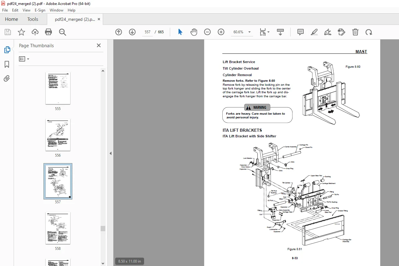
Lift Bracket Service. 6-43
Fork Carriage Removal6-43
Models Equipped with Sideshift Only . 6-43
Models Equipped with Tilt Only6-44
Servicing Lift Bracket Arm Rollers . 6-45
Tilt Cylinder Overhaul6-47
Cylinder Removal . 6-47
ITA Lift Brackets
ITA Lift Bracket with Sidesifter6-47
ITA Lift Bracket without Sideshifter . 6-48
Cylinder Removal. 6-48
Preparation and Cleaning6-48
Disassembly. 6-49
Retainer Assembly . 6-49
Piston Rod and Assembly6-49
Cleaning and Inspection . 6-50
Reassembly . 6-50
Retainer Assembly . 6-50
Reach Cylinder Overhaul
Cylinder Removal 6-50
Remove Forks 6-50
Remove the Fork Carriage. 6-51
Preparation, Cleaning and Inspection . 6-51
Disassembly . 6-53
Retainer Assembly . 6-53
Piston Rod and Piston . 6-53
Cleaning and Inspection6-53
Reassembly6-54
Retainer Assembly 6-54
vii
TABLE OF CONTENTS
MAST (continued)
Sideshift Cylinder Overhaul
Cylinder Removal—Lift Bracket6-55
Remove Forks 6-55
Preparation Cleaning and Inspection6-55
Disassembly . 6-55
Retainer Assembly . 6-55
Lift Bracket Service
Cleaning and Inspection . 6-57
Reassembly6-57
Reach and Sideshift Selector Valve
Preparation . 6-57
Mast Hydraulic Schematic 6-59
Reach and Tilt Selector Valve
Removal 6-60
Disassembly . 6-60
Mounting Selector Valve . 6-60
Connecting Hydraulic Plumbing6-61
Sideshifter Solenoid Control Valve
Removal 6-62
Installation6-63
Mount Selector Valve . 6-63
Install Hoses6-63
Connect Coils6-63
Servicing a Double Reach Lift Bracket . 6-64
Installing Reach Cylinders . 6-66
Reach and Tilt Selector Valve Service
Disassembly . 6-67
Cleaning . 6-68
Reassembly—Solenoid Valves 6-69
Reassembly—Counterbalance Valves6-71
Installation6-71
Sideshifter Selector Valve
Disassembly . 6-72
Cleaning . 6-72
Reassembly6-73
Mast Triline Hose / Cable Routing . 6-74
Field Replacement of Mast Triline Harness6-75
Mast “Auxiliary” Hydraulic Flushing Procedure . 6-77
viii
TABLE OF CONTENTS
HYDRAULIC SCHEMATICS
Legend. 7-1
Standard Performance with Tilt . 7-2
Standard Performance with Tilt and Sideshift7-3
High Performance with Tilt . 7-4
High Performance with Tilt and Sideshift . 7-5
CONTROLLER
System Configuration and Outline8-1
System Configuration 8-1
Outline8-2
Logic Unit. 8-2
Inverter. 8-2
Output Unit (RIO). 8-3
Display Unit 8-3
APS (Advanced Power Steering) Unit8-3
External Logic. 8-4
Logic Unit. 8-4
Inverter. 8-5
Output Unit. 8-6
Display Unit 8-7
Controller Area Network (CAN). 8-8
AC Motor System Basics8-9
Feature of AC Motor8-9
Speed Control of Induction Motor8-9
Inverter. 8-10
Function. 8-11
Traction Control Function8-11
Powering8-11
Limitation of Maximum Travel Speed 8-12
Regeneration . 8-13
Controlled Roll Back8-13
Steering . 8-14
Stall Timer 8-14
Free Lift 8-14
Hydraulic Control Function 8-16
Hydraulic Controller . 8-16
Priority . 8-17
Inhibition of Simultaneous Operation . 8-17
Attachments 2 and 3 8-17
Steering Control Function . 8-18
OPP (Operator Presence Pedal) Function8-19
Preventing Operator’s Absence 8-19
Other Functions8-20
ix
TABLE OF CONTENTS
CONTROLLER (continued)
BDI (Battery Discharge Indicator)8-20
Service Indicator8-20
Hour Meter Function8-20
Chime Control Function . 8-21
Battery Voltage Monitor 8-21
Display Function (See Display Section)8-22
Normal Operation Display 8-22
Error Display8-23
Password Display. 8-23
Removal and Installation 8-24
Inspecting Before Replacing Controllers. 8-24
Checking Inverter and DSP Card. 8-24
Checking Logic Card 8-25
Checking Power Supply Card8-26
Checking Output Unit. 8-27
Checking Display Unit8-28
Discharging Electric Charges from Inverters and APS Unit8-29
Replacing Inverter. 8-30
Replacing DSP (Digital Signal Processor) Card . 8-32
Replacing Logic Unit. 8-34
Replacing Logic Card . 8-35
Replacing Power Supply Card8-36
Replacing Output Unit. 8-37
Replacing APS (Advanced Power Steering) Unit8-38
Basic8-38
Basic Items . 8-38
Testing Tools . 8-38
Pin by Pin Voltage Measurement8-39
Pin by Pin Measurement Chart . 8-40
Coil Resistances . 8-50
Checking Contactor 8-51
Checking Contactor Coil . 8-51
Checking Contactor Tip8-51
Checking Inverter 8-52
Regeneration Check . 8-52
TROUBLESHOOTING FOR CONTROL CIRCUITS
General Information 9-1
Before Replacing Devices. 9-1
Connection of the Service Tool . 9-1
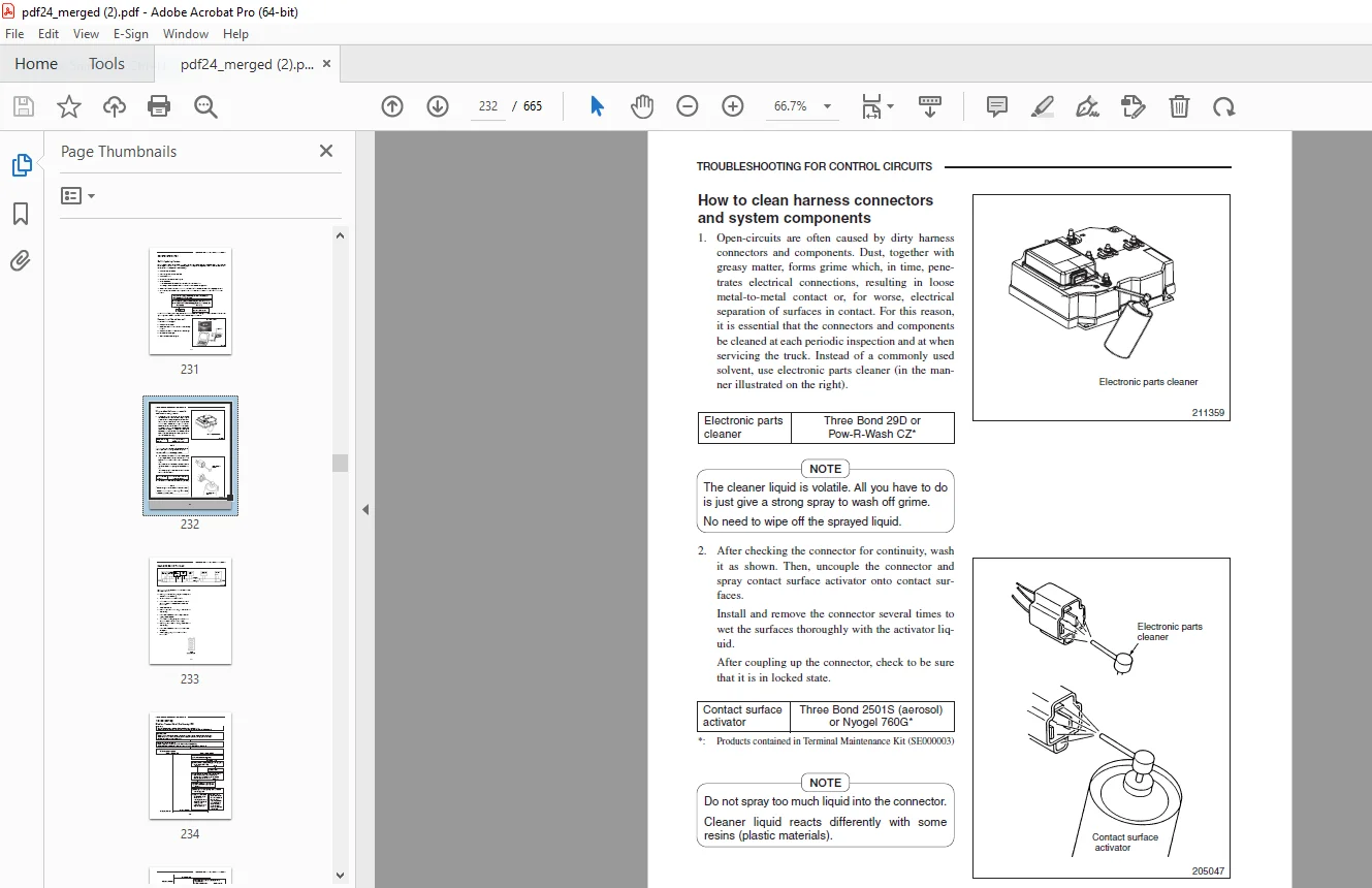
How to Clean Harness Connectors and System Components 9-2
CAN-BUS Reach Truck AC . 9-3
x
TABLE OF CONTENTS
TROUBLESHOOTING FOR CONTROL CIRCUITS (continued)
Troubleshooting9-4
E0 Traction Motor, Overheating 9-4
E2 Pump Motor 1, Overheating . 9-8
E3 Pump Motor 2, Overheating . 9-11
E4 Steer Motor, Overheating . 9-14
E5 Traction Inverter, Overheating. 9-17
E7 Pump Inverter 1, Overheating9-20
E8 Pump Inverter 2, Overheating9-23
E9 Steer Inverter, Overheating9-26
A5 Traction Motor, Over-Current . 9-29
14 Traction Motor Current Sensor Fault . 9-32
15 Traction Motor, Over-Current. 9-34
16 Traction Motor, Stall Timer Speed Fault9-37
34 Pump Motor 1, Current Sensor Fault9-39
35 Pump Motor 1, Over-Current9-41
40 Line Contactor Fault . 9-44
45 Traction Motor Open . 9-46
47 Pump Motor 1, Open9-49
48 Pump Motor 2, Open9-52
49 Steer Motor, Open9-55
51 Traction Lever Sensor Fault9-58
52 Traction Motor Pulse Input Fault . 9-61
55 FC Solenoid Fault . 9-64
56 FC Solenoid Current Leak9-67
57 Pump Motor 1 Pulse Input Fault . 9-69
58 Pump Motor 2 Pulse Input Fault . 9-72
59 Steer Motor Pulse Input Fault . 9-75
60 Display Communication Fault . 9-78
61 Parameter Write Fault . 9-81
62 Logics Fault9-82
63 Traction Inverter Fault . 9-83
65 Pump Inverter 1 Fault . 9-86
66 Pump Inverter 2 Fault . 9-89
68 Output Unit Fault9-92
71 APS Controller Fault . 9-94
78 Battery Voltage Too Low . 9-96
79 Battery Voltage Too High9-98
81 Pressure Sensor Fault9-100
82 Steer Stepper Motor Fault9-103
85 Brake Switch Fault9-105
86 Height Sensor Fault9-107
88 Logic Fault Multipurpose Output #1, Travel Alarm9-110
88 Logic Fault Multipurpose Output #2, Horn9-112
94 Pump Motor 2, Current Sensor Fault9-114
95 Pump Motor 2, Over-Current . 9-116
xi
TABLE OF CONTENTS
TROUBLESHOOTING FOR CONTROL CIRCUITS (continued)
(E) Incorrect Start9-119
(H1) Lift Lever, Faulty Setting9-121
(H2) Tilt Switch, Faulty Setting. 9-123
(H3) Reach Switch, Faulty Setting . 9-125
(H4) Sideshift Switch, Faulty Setting 9-127
(Lo) Battery Low9-129
Component Identification. 9-131
Electrical Diagrams. 9-135
Wiring Schematic
Wiring Diagram
PLANNED MAINTENANCE
Maintenance Locations10-1
Maintenance Intervals10-2
Service Data
Recommended Lubricants10-3
Fluid Capacities10-3
G.B 27/01/25