Mitsubishi Forklift ESR15N-36V ESR18N-36V ESR20N-36V ESR20HN-36V ESR23N-36V ESR23HN-36V EDR13N-36V EDR15N-36V EDR15HN-36V ESS15N-36V ESS20N-36V Service Manual PDF
$28.95
Mitsubishi Forklift Truck ESR15N-36V ESR18N-36V ESR20N-36V ESR20HN-36V ESR23N-36V ESR23HN-36V EDR13N-36V EDR15N-36V EDR15HN-36V ESS15N-36V ESS20N-36V P.NO WENB2900-03 Service Manual – PDF DOWNLOAD
- Chassis, Mast & Options
ESR15N-36V 2SR3300700-up
ESR18N-36V 4SR3300700-up
ESR20N-36V 5SR3300700-up
ESR20HN-36V 6SR3300700-up
ESR23N-36V 7SR3300700-up
ESR23HN-36V 8SR3300700-up
EDR13N-36V 1DR3300700-up
EDR15N-36V 2DR3300700-up
EDR15HN-36V 3DR3300700-up
ESS15N-36V 2SS3300700-up
ESS20N-36V 5SS3300700-up
Description
Mitsubishi Forklift Truck ESR15N-36V ESR18N-36V ESR20N-36V ESR20HN-36V ESR23N-36V ESR23HN-36V EDR13N-36V EDR15N-36V EDR15HN-36V ESS15N-36V ESS20N-36V Service Manual P.NO WENB2900-03 – PDF DOWNLOAD
FILE DETAILS:
Mitsubishi Forklift Truck ESR15N-36V ESR18N-36V ESR20N-36V ESR20HN-36V ESR23N-36V ESR23HN-36V EDR13N-36V EDR15N-36V EDR15HN-36V ESS15N-36V ESS20N-36V P.NO WENB2900-03 Service Manual – PDF DOWNLOAD
Language : English
Pages : 296
Downloadable : Yes
File Type : PDF
IMAGES PREVIEW OF THE MANUAL:
TABLE OF CONTENTS:
Mitsubishi Forklift Truck ESR15N-36V ESR18N-36V ESR20N-36V ESR20HN-36V ESR23N-36V ESR23HN-36V EDR13N-36V EDR15N-36V EDR15HN-36V ESS15N-36V ESS20N-36V P.NO WENB2900-03 Service Manual – PDF DOWNLOAD
- Chassis, Mast & Options
ESR15N-36V 2SR3300700-up
ESR18N-36V 4SR3300700-up
ESR20N-36V 5SR3300700-up
ESR20HN-36V 6SR3300700-up
ESR23N-36V 7SR3300700-up
ESR23HN-36V 8SR3300700-up
EDR13N-36V 1DR3300700-up
EDR15N-36V 2DR3300700-up
EDR15HN-36V 3DR3300700-up
ESS15N-36V 2SS3300700-up
ESS20N-36V 5SS3300700-up
INSTALLATION INSTRUCTIONS
Truck
How the Truck is Shipped 1-1
Uprighting a Cradled Truck 1-1
Option 1: Uprighting with Two Chain Hoist 1-1
Option 2: Uprighting with One Chain Hoist and a Forklift Truck 1-2
Mast Installation Instructions
Truck System Requirements 1-3
Mast Inspection 1-3
Chain Lubrication 1-3
Upright and Carriage Position, Chain Tension 1-3
Channel Lubrication 1-3
Mast Mounting Bolts and Torque Specifications 1-4
Overhead Guard Mounting Bolts and Torque Specifications 1-5
Hydraulic Fluid Level 1-6
Hydraulic Functions 1-6
Pump Intake Coupling (Bleed Points) 1-6
2 GENERAL INFORMATION & FEATURES
Glossary 2-1
Reach Truck Serial Number Definition 2-3
General Overview 2-4
Jacking Truck 2-7
Load Wheel Replacement Guide 2-8
Caster Adjustment 2-9
Brake Assembly Inspection and Adjustment 2-10
Adjustment of Air Gap with Brake Applied 2-10
Friction Disc Replacement 2-10
Drive Assembly 2-12
3 THEORY OF OPERATIONS
How to Determine whether it is a 4 Valve Truck or a 6 Valve Truck 3-1
4 Valve Configuration 3-2
Solenoid Valve Activation Chart 3-2
Main Hydraulic Manifold 3-2
6 Valve Configuration 3-3
Solenoid Valve Activation Chart 3-3
Main Hydraulic Manifold 3-3
Theory of Operation 3-4
Plugging in the Battery 3-4
B- feed to 3-4
Additional Safety Circuit (Emergency Power Off) 3-4
Turning Key Switch (S2) ON 3-4
Can Bus Communications 3-5
Stepping on the Operator Presence Pedal 3-5
Steer Request 3-6
Electric Steer Controller 3-6
Travel Request 3-7
Plugging Request 3-8
Regenerative Braking 3-9
Lift Activation 3-10
Lower Activation 3-10
Auxiliary Functions 3-11
Tilt Request 3-12
Tilt Activation 3-12
iii
TABLE OF CONTENTS
3 THEORY OF OPERATIONS (continued)
Reach/Retract and Side Shift Activation 3-12
Side Shift Activation 3-12
Lift Pressure Adjustment 3-13
Emergency Lowering 3-13
4 OPERATOR DISPLAY
Operator Display 4-1
Battery State-of-Charge 4-2
Parking Brake 4-2
Clock 4-2
Mode of Operation 4-2
Travel Direction 4-2
Travel Speed Indicator 4-2
Text Messaging 4-2
Height Selector Levels (optional) 4-2
Load Weight Display 4-3
Thermal Monitoring 4-4
5 OPERATOR DISPLAY INFORMATION & PROGRAMMING
Note on Passwords 5-1
Programming and Set Up of Performance Values 5-1
Console Switches and Functions 5-1
Main Menu Items 5-1
Main Menu I
Parameters 5-2
Parameter 1 5-2
Parameter 2 5-2
Parameter 3 5-2
Tester Master (Diagnostics) 5-2
Tester 1 5-3
Tester 2 5-3
Tester Slave 5-3
Tester 1 5-3
Tester 2 5-4
Tester 3 5-4
Tester 4 5-4
Tester 5 5-4
Tester 6 5-4
To Access AutoTeaching (Option) 5-4
Alarms 5-5
To Access Alarms 5-5
To Access Lift Limit (Option) 5-5
Main Menu II
Insert Password 5-6
Program Password 5-6
Adjust Time and Date 5-7
Language Select 5-7
Main Menu III
Service Mode 5-8
6 SETTINGS AND PARAMETERS
Section Overview 6-1
General Information—Handset 6-1
TABLE OF CONTENTS
iv
6 SETTINGS AND PARAMETERS (continued)
Handset—Tree Diagram 6-1
Handset—Menu Description 6-1
PC Software / Handset for the 36V A/C Reach Truck
To Change Controllers using the PC 6-2
To Change Parameters 6-2
To Change Controllers using Handset 6-2
SICOS
Display Controller (SICOS) Flow Chart 6-8
Default Settings (Display Controller “SICOS”) 6-9
Parameter Change (Display Controller “SICOS”) 6-11
Tester (Display Controller “SICOS”) 6-12
Alarms (Display Controller “SICOS”) 6-13
Set Options (Display Controller “SICOS”) 6-14
Adjustments (Display Controller “SICOS”) 6-15
MHYRIO
Valve Controller (MHYRIO) Flowchart 6-16
Default Settings (Valve Controller “MHYRIO”) 6-17
Parameter Change (Valve Controller “MHYRIO”) 6-18
Tester (Valve Controller “MHYRIO”) 6-20
Alarms (Valve Controller “MHYRIO”) 6-22
Set Options (Valve Controller “MHYRIO”) 6-23
Traction Controller (AC2)
Traction Controller Flow Chart 6-24
Default Settings (Traction Controller) 6-25
Parameter Change (Traction Controller) 6-26
Tester (Traction Controller) 6-27
Alarms (Traction Controller) 6-28
Set Options (Traction Controller) 6-30
Adjustments (Traction Controller) 6-31
Pump Controller (AC2/AC3)
Pump Controller Flow Chart 6-32
Default Settings (Pump Controller) 6-33
Parameter Change (Pump Controller) 6-35
Tester (Pump Controller) 6-36
Alarms (Pump Controller) 6-37
Set Options (Pump Controller) 6-39
Adjustments (Pump Controller) 6-39
EPS Controller
Electric Steer Controller (EPS) Flow Chart 6-40
Default Setting (Electric Steer Controller “EPS”) 6-41
Parameter Changes (Electric Steer Controller “EPS”) 6-42
Tester (Electric Steer Controller “EPS”) 6-43
Alarms (Electric Steer Controller “EPS”) 6-44
Set Options (Electric Steer Controller “EPS”) 6-46
Adjustments (Electric Steer Controller “EPS”) 6-47
7 SET UP AND OPTION INSTALLATION
Adjustments
Potentiometer Adjustment Overview 7-1
Traction Speed & Direction Sensor Potentiometer R12 & Related Config Menu Items 7-1
Lift/Lower Potentiometer R13 and Related Config Menu Items 7-1
Potentiometer Calibration Procedure 7-1
Date and Time Settings 7-2
Setting the Date and Time 7-2
TABLE OF CONTENTS
7 SET UP AND OPTION INSTALLATION (continued)
Enabling the Maintenance Alarm 7-3
Setting Hours for the Maintenance Alarm 7-3
Metric or English Values Displayed 7-3
Audible Travel Alarm (Optional) 7-4
Forward Steering Kit 7-5
Free Lift Sensor
Height Detection Overview 7-6
Height Detection Installation 7-7
Height Display Activation 7-8
Pre-Height Selector Activation 7-8
Auto Teaching (Option) 7-8
Operation Instructions for Pre-Selected Shelf Height Selector 7-9
Lift Limit with Bypass 7-10
Load Weight
Load Weight Installation 7-10
Weight Function 7-10
Maximum Weight Setting 7-11
Minimum Load Adjustment 7-11
Maximum Load Adjustment 7-11
Keyless Entry Option
Keyless Entry Programming Guide 7-13
Keyless Entry Schematic 7-16
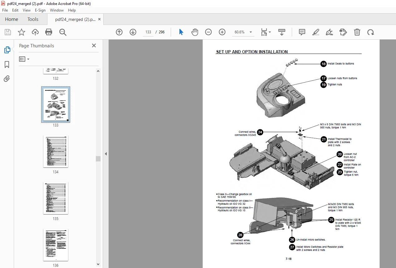
Cold Storage Option 7-17
8 MAST
Contents 8-1
Periodic Inspection 8-1
Inspection 8-1
500 Hour Inspection 8-1
Troubleshooting 8-3
Mast Removal 8-5
Cylinders
Main Lift Cylinder 8-4
Free Lift Cylinder 8-6
Cylinder Operation 8-9
Main Lift Cylinder Service 8-11
Free Lift Cylinder Service 8-14
Mast Uprights
Upright Description 8-17
Upright Chain Inspection 8-18
Cracked Plates 8-19
Ultimate Strength Failure 8-19
Tight Joints 8-19
Chain Length Adjustments
Periodic Inspection—Triple-Stage Upright (TSU) Chain Length Adjustments 8-20
Periodic Inspection—Chain Lubrication 8-22
General Guidelines 8-22
Chain Removal and Replacement 8-23
Lift Chains (Standard & TSU) 8-23
Primary Cylinder/Carriage Chains (TSUs) 8-23
Other Chain Service Notes 8-23
Periodic inspection—Upright & Lift Bracket Removal & Replace Roller Shim Adjustments
Lift Bracket Removal Preparation 8-24
Removal & Replace Roller Shim 8-25
Upright & Lift Bracket Removal 8-26
Upright Removal 8-31
v
TABLE OF CONTENTS
vi
MAST (continued)
Upright Disassembly
Rail Cylinders—Rollers and Shims 8-33
Cable, Hose and Chain Sheaves 8-33
Free Lift Cylinder 8-33
Cable and Chain Sheaves 8-34
Shimming 8-35
Lift Bracket Assembly
Checks and Adjustments 8-36
Shimming
Roller Clearance Inspection—Service 8-41
Checking Lower Roller Clearance with upright 6″ from fully retracted position 8-41
When using a Pry Bar 8-41
“C” Clamp Method 8-42
Determining the Number of Shims needed to make roller adjustment 8-47
Shim Adjustment 8-48
Lift Bracket & Fork Carriage Assembly 8-48
Fork Removal 8-49
Lift Bracket Service—Fork Carriage Removal
Models Equipped with Side Shift Only 8-49
Model Equipped with Tilt Only 8-50
Servicing Lift Bracket Arm Rollers 8-51
Tilt Cylinder Overhaul—Cylinder Removal 8-53
ITA Lift Bracket with Side Shifter 8-53
ITA Lift Bracket without Side Shifter 8-54
Cylinder Removal 8-54
Disassembly 8-55
Retainer Assembly 8-55
Piston Rod and Piston 8-55
Cleaning and Inspection 8-56
Reassembly 8-56
Retainer Assembly 8-56
Reach Cylinder Overhaul—Cylinder Removal
Remove the Fork Carriage 8-57
Preparation, Cleaning And Inspection 8-57
Disassembly 8-59
Retainer Assembly 8-59
Piston Rod and Piston 8-59
Cleaning and Inspection 8-59
Reassembly 8-60
Retainer Assembly 8-60
Sideshift Cylinder Overhaul—Cylinder Removal
Remove Forks 8-61
Preparation, Cleaning And Inspection 8-61
Disassembly 8-61
Retainer Assembly 8-61
Cleaning and Inspection 8-63
Reassembly 8-63
Reach and Side Shift Selector Valve
Preparation 8-63
Hydraulic Schematic
For Mast model S/N 40HR-MT-001 through 40HR-MT-111 and
For Mast model S/N 45HR-MT-001 through 45HR-MT-102 8-65
For Mast model S/N 40HR-MT-112 through Present and
For Mast model S/N 45HR-MT-103 through Present 8-66
TABLE OF CONTENTS
MAST (continued)
Reach and Tilt Selector Valve
Disassembly 8-67
Mounting Selector Valve 8-67
Connecting Hydraulic Plumbing 8-68
Lift Bracket Service
Side Shifter Solenoid Control Valve 8-68
Installation—Mount Selector Valve 8-69
Install Hoses 8-69
Connect Coils 8-69
Servicing a Double Reach Lift Bracket 8-70
Double Reach Without Sideshifter 8-70
Installing Reach Cylinders 8-72
Reach and Tilt Selector Valve Service
Disassembly 8-73
Cleaning 8-74
Reassembly—Solenoid Valves 8-75
Reassembly Counterbalance Valves 8-77
Installation 877
Side Shift Selector Valve Service
Disassembly 8-78
Cleaning 8-78
Reassembly 8-79
Mast Triline Hose / Cable Routing 8-80
Mast to Pantograph Cable Assembly 8-80
Field Replacement of Mast Triline Hoses 8-81
Mast “Auxiliary” Hydraulic Flushing Procedure 8-83
9 HYDRAULIC SCHEMATICS
Hydraulic Legend 9-1
4 Valve Hydraulic Schematic 9-2
6 Valve Hydraulic Schematic 9-3
10 ELECTRICAL
Diagram of Controllers 10-1
How to Use Schematic 10-1
Standard Performance Schematic—Power Supply 36 Volt (1/12) 10-2
Standard Performance Schematic—Main Power Circuits (2/12) 10-3
Standard Performance Schematic—Drive Circuits (3/12) 10-4
Standard Performance Schematic—Steering Circuits (4/12) 10-5
Standard Performance Schematic—Hydraulic Control Circuits (5/12) 10-6
Standard Performance Schematic—Hydraulic Control Output Circuits—4 Valve (6/12) (a) 10-7
Standard Performance Schematic—Hydraulic Control Output Circuits—6 Valve (6/12) (b) 10-8
Standard Performance Schematic—Keypad Switches Hydraulic Sensing Circuits (7/12) 10-9
Standard Performance Schematic—Pump & Traction Encoders/Temp Sensing Circuits (8/12) 10-10
Standard Performance Schematic—Communications Connections (9/12) 10-11
Standard Performance Schematic—Horn, Lights and Travel Alarm (10/12) 10-12
Standard Performance Schematic—Fans (11/12) 10-13
Standard Performance Schematic—Cold Storage Use—Option (12/12) 10-14
High Performance Schematic—Power Supply 36 Volt (1/12) 10-15
High Performance Schematic—Main Power Circuits (2/12) 10-16
High Performance Schematic—Drive Circuits (3/12)10-17
High Performance Schematic—Steering Circuits (4/12)10-18
High Performance Schematic—Hydraulic Control Circuits (5/12) 10-19
vii
TABLE OF CONTENTS
viii
High Performance Schematic—Hydraulic Control Output Circuits—4 Valve (6/12) (a) 10-20
High Performance Schematic—Hydraulic Control Output Circuits—6 Valve (6/12) (b) 10-21
High Performance Schematic—Keypad Switches Hydraulic Sensing Circuits (7/12)10-22
High Performance Schematic—Pump & Traction Encoders/Temp Sensing Circuits (8/12)10-23
High Performance Schematic—Communications Connections (9/12) 10-24
High Performance Schematic—Horn, Lights and Travel Alarm (10/12)10-25
High Performance Schematic—Fans (11/12) 10-26
High Performance Schematic—Cold Storage Use—Option (12/12) 10-27
Standard 1425 Schematic—Power Supply 36 Volt (1/12) 10-28
Standard 1425 Schematic—Main Power Circuits (2/12)10-29
Standard 1425 Schematic—Drive Circuits (3/12) 10-30
Standard 1425 Schematic—Steering Circuits (4/12) 10-31
Standard 1425 Schematic—Hydraulic Control Circuits (5/12)10-32
Standard 1425 Schematic—Hydraulic Control Output Circuits—4 Valve (6/12) (a) 10-33
Standard 1425 Schematic—Hydraulic Control Output Circuits—6 Valve (6/12) (b) 10-34
Standard 1425 Schematic—Keypad Switches Hydraulic Sensing Circuits (7/12)10-35
Standard 1425 Schematic—Pump & Traction Encoders/Temp Sensing Circuits (8/12)10-36
Standard 1425 Schematic—Communications Connections (9/12)10-37
Standard 1425 Schematic—Horn, Lights and Travel Alarm (10/12)10-38
Standard 1425 Schematic—Fans (11/12)10-39
Standard 1425 Schematic—Cold Storage Use—Option (12/12)10-40
11 TROUBLESHOOTING
Display Information Example 11-1
Sicos Alarms and Warnings (MOD #1) 11-1
AC-2 Alarms and Warnings (MOD #2) (MOD #5) 11-2
EPS Alarms and Warnings (MOD #6) 11-4
MHYRIO Alarms and Warnings (MOD #9) 11-5
Pin by Pin Voltages 11-8
Coil Resistances 11-18
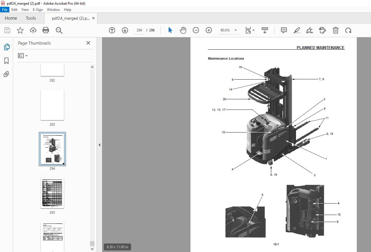
12 PLANNED MAINTENANCE
Maintenance Locations 12-1
Maintenance Intervals 12-2
Recommended Oils 12-3
Fluid Capacities 12-3
DESCRIPTION:
Mitsubishi Forklift Truck ESR15N-36V ESR18N-36V ESR20N-36V ESR20HN-36V ESR23N-36V ESR23HN-36V EDR13N-36V EDR15N-36V EDR15HN-36V ESS15N-36V ESS20N-36V P.NO WENB2900-03 Service Manual – PDF DOWNLOAD
Mitsubishi Forklift Trucks Important Safety Information:
- Most accidents involving product operation, maintenance and repair are caused by failure to observe basic safety rules and precautions. An accident can often be avoided by recognizing potentially hazardous situations before an accident occurs. A person must be alert to potential hazards. This person should also have the necessary training, skills and tools to perform these functions properly.
- Improper operation, lubrication, maintenance or repair of this product can be dangerous and could result in injury or death.
- Do not operate or perform any lubrication, maintenance or repair on this product, until you have read and understood the operation, lubrication, maintenance and repair information.
- Safety precautions and warnings are provided in this manual and on the product. If these hazard warnings are not heeded, bodily injury or death could occur to you or other persons.
G.B 27/01/25