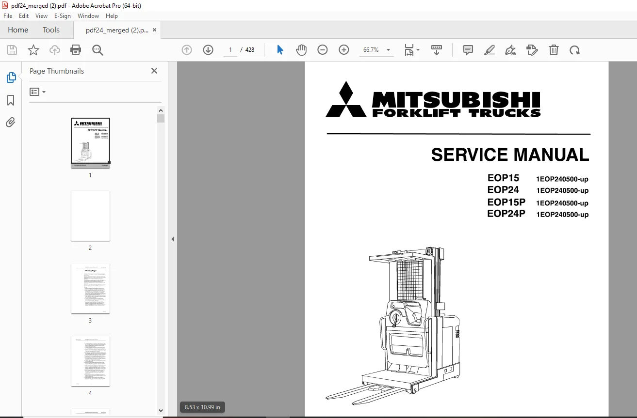
Mitsubishi Forklift EOP15 EOP24 EOP15P EOP24P Service Manual P.NO WENB8560-01 PDF
$29.95
Mitsubishi Forklift Truck EOP15 EOP24 EOP15P EOP24P Service Manual P.NO WENB8560-01 – PDF DOWNLOAD
- EOP15 1EOP240500-up
EOP24 1 EOP240500-up
EOP1 SP 1 EOP240500-up
EOP24P 1 EOP240500-up
Description
Mitsubishi Forklift Truck EOP15 EOP24 EOP15P EOP24P Service Manual P.NO WENB8560-01 – PDF DOWNLOAD
FILE DETAILS:
Mitsubishi Forklift Truck EOP15 EOP24 EOP15P EOP24P Service Manual P.NO WENB8560-01 – PDF DOWNLOAD
Language : English
Pages : 428
Downloadable : Yes
File Type : PDF
IMAGES PREVIEW OF THE MANUAL:
TABLE OF CONTENTS:
Mitsubishi Forklift Truck EOP15 EOP24 EOP15P EOP24P Service Manual P.NO WENB8560-01 – PDF DOWNLOAD
- EOP15 1EOP240500-up
EOP24 1 EOP240500-up
EOP1 SP 1 EOP240500-up
EOP24P 1 EOP240500-up
Warning Pages
Manual Overview
MITSUBISHI Orderpicker Service Manual
Table of Contents
Table of Contents
a
i
Using the Manual i
Table of Contents
Description
iii
1-1
Truck Overview 1-2
Use 1-2
‘fype 1-2
Power 1-3
Capacity 1-3
Mast 1-3
Controls 1-3
Indicators1-3
Vehicle Specification 1-4
Specification Plate 1-5
Mechanical 1-7
Chassis 1-8
Power Section Frame 1-8
Battery Compartment 1-8
Battery Connector1-8
Outriggers 1-8
Covers 1-8
Mast Assembly 1-9
Mast Main Frame 1-9
Telescopic Frame(s) 1-9
Mast Bearings1-9
Forks 1-9
Operator’s Compartment 1-9
Compartment Dimensions1-9
Compartment Floor 1-9
Side Gates1-9
Overhead guard 1-10
Tether 1-10
Operator’s Controls 1-10
Operator Compartment Options 1-10
Steering 1-12
iii PDMM-0067
Table of Contents MITSUBISHI Orderpicker Service Manual
Drive Unit 1-12
Pivot Bearing1-12
Gear Housing 1-12
Gear Reduction Assembly 1-12
Drive Motor 1-12
Drive Wheel 1-12
Hydraulic 1-13
Lift/Lower System 1-13
Lift Pump 1-13
Lift Motor 1-13
Lift Cylinder Assembly 1-13
Flow Controls1-13
Reservoir1-13
Return Line Filter 1-13
Lift Chain 1-13
Lift/Lower Hydraulic Manifold Assembly 1-14
Solenoid 1 (SOLl) 1-15
Solenoids 2 and 3 (SOL2) and (SOL3) 1-15
Solenoid 3 (SOL3) 1-15
Electrical1-19
General 1-19
System Displays1-19
Operator System Display 1-19
Steering Indicator or Keypad (Optional) 1-19
Maintenance Displays1-20
Electronic Control System 1-20
Interface Card Assembly 1-20
Carriage Wiring Board 1-20
Travel System 1-21
EVl00LX System 1-21
Drive Motor 1-21
Travel Contactors 1-21
Coil Drivers 1-21
Directional/Speed Control Assembly 1-22
24″ Mast Switch (Sll) 1-22
150″ Mast Switch (S26) 1-22
Solenoid 12 (SOL12) (Vehicles equipped with electronic power steering) 1-22
Electric Steering1-23
Kill (Deadman) Switch (S2) 1-23
Emergency off Switch (S21) 1-23
Over-the-Mast Cables 1-23
Miscellaneous Circuits 1-29
Options 1-30
Wire Guidance 1-30
PDMM-0067 iv
MITSUBISHI Orderpicker Service Manual Table of Contents
Unpacking and Inspection 2-1
Receiving Truck 2-2
Reasons For Visual Inspections 2-2
What to Look For 2-2
Visual Inspection/Conditions 2-2
Installation Procedure 2-4
Cradled Trucks 2-5
Visual Inspection 2-5
Uncradling 2-6
Uprighting a Cradled Vehicle 2-6
Procedure 1 2-6
Procedure 2 2-7
Gasket Removal 2-8
Greasing Mast Uprights 2-8
Battery 2-8
Battery Charger 2-8
Battery Installation2-9
Functional Inspection 2-10
Vehicle Operation 2-10
Warranty2-10
What To Look For 2-10
Functional Installation Checklist2-11
Cold Storage Conditioning 2-12
‘fypes of Oils 2-12
Classes of Cold Storage 2-12
Hydraulic System Oil Change Procedure 2-13
Storage 2-14
Storage Warranty2-14
Motors 2-14
Hydraulic System 2-14
Hydraulic Cylinders 2-14
Lift/Steering Chains 2-14
Electronics 2-14
Battery 2-15
Greasing Mast Uprights 2-15
Vehicle – General2-15
V PDMM-0067
Table of Contents MITSUBISHI Orderpicker Service Manual
Operating Instructions 3-1
EVl00LX Operator System Display 3-2
Display Test 3-2
Hour Meter 3-2
Battery Discharge Indicator 3-2
Status Codes 3-2
Informational Messages 3-3
Performance Limiting Codes 3-3
Fault Codes (For trucks with electronic power steering and wire guidance) 3-4
Audible Alarm (For trucks with electronic power steering)3-4
Operator’s Daily Checklist 3-5
Visual Checks3-5
Operational Checks 3-5
Start Up Procedure 3-6
Forward/Reverse Travel 3-6
Braking 3-7
Plugging 3-7
Parking 3-7
Electronic Power Steering Modes of Operation3-8
Run Mode3-8
Configure Mode 3-8
Maintenance Mode 3-8
Learn Mode 3-8
Piezo Sounder3-9
Piezo Sounder Tone Patterns 3-9
Passwords 3-10
To Enter Or Change A Password 3-10
Entering CONFIG or MAINT Mode 3-13
Configure Mode 3-14
Configure Mode Standard Features 3-15
Configure Mode Program Tree3-16
Maintenance Mode Program Tree3-1 7
Maintenance Mode 3-18
Static Maintenance Mode3-18
Active Maintenance Mode3-19
Learn 3-20
When to Run Learn 3-20
Details Pertaining to Learn 3-21
Learning Wire Frequency 3-21
Learning Guide Wire Offsets 3-22
Learning Steer 3-23
PDMM-0067 vi
MITSUBISHI Orderpicker Service Manual Table of Contents
Theory of Operation 4-1
EVl00LX Control Panel 4-2
System Components 4-2
Silicon Controlled Rectifiers 4-2
Diode Rectifiers 4-3
Thermal Protector (TP)4-3
Sensor (Sensor 1) 4-3
Control Features 4-5
Creep Speed 4-5
Controlled Acceleration4-5
Current Limit 4-5
Plugging 4-5
IA Current Dropout 4-6
Speed Limit 1 /Speed Limit 3 4-6
Static Return to Off 4-6
Accelerator Volts Hold-Off 4-6
Coil Driver Modules 4-6
Thermal Cutback 4-7
Pulse Monitor Trip (PMT) 4-7
Internal Resistance Compensation4-7
Stored Fault Code 4-7
Battery Discharge Indication 4-8
Hour Meter4-8
On Board Diagnostics 4-8
Basic SCR Controller Circuit Operation 4-9
Wiring Conventions 4-12
Operation of The Travel System 4-13
Introduction 4-13
Sequence 1 – Truck at Rest 4-13
Sequence 2 – Connect the Battery 4-13
Sequence 2A – Keyswitch is Closed (S-1) 4-14
Sequence 3 -Closing the Deadman Switch 4-14
Sequence 4 – PMT Test 4-14
Sequence 5 – Directional Contactor Closure 4-15
Sequence 6 – REC 1 Turn On4-15
Sequence 7 – REC 5 Turn On4-16
Sequence 8 – Reverse Charging the 1 C Capacitor4-16
Sequence 9 – REC 2 Turn On and REC 1 Turn Off 4-1 7
Sequence 10 – Flyback Current 4-1 7
Sequence 11 – IA or Bypass Contactor Operation4-18
Sequence 12 – Controlled Plugging 4-19
Lift/Lower System 4-20
System Overview4-20
Unique System Features 4-20
Single-Speed Lift/Lower 4-21
Two-Speed Lift/Lower 4-24
vii PDMM-0067
Table of Contents MITSUBISHI Orderpicker Service Manual
Two-Speed Lift/Lower Functions 4-25
Lift/Lower Functional Block Diagram 4-26
Fork Hang-Up Protection 4-27
Braking 4-28
Process 4-28
Steering 4-29
Manual Cable Steering 4-29
Manual Cable Steering Theory of Operation 4-30
Electronic Power Steering 4-30
Electronic Power Steer System (Optional) 4-31
Signal Paths 4-31
Signal Interface 4-31
Theory of Operation 4-34
Steer Controller Card 4-37
Display Card4-39
Filter Card 4-40
Steer Encoder Card 4-41
Steer Position Encoder (SPE) 4-41
Home Proximity Sensor (HP) 4-41
Speed Prox 1 and Speed Prox 2 Sensors 4-41
1 0o Position Sensor (Manual Steer Only) 4-41
Carriage Wiring Board 4-42
BUS + /BUS- 4-42
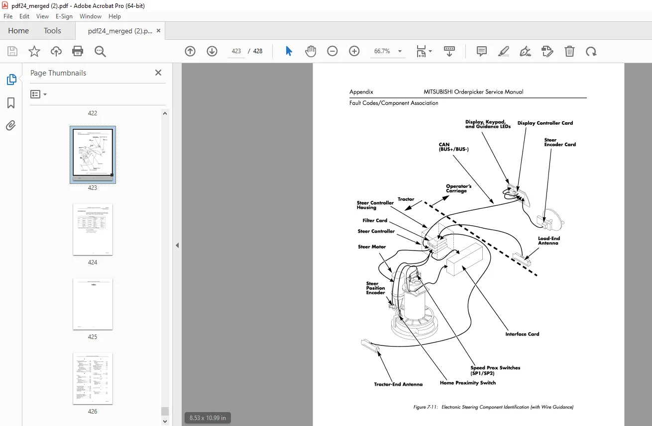
Wire Guidance 4-43
Systems Concept4-43
Warehouse Installed Equipment (WIE) 4-43
Truck Installed Equipment (TIE)4-43
Antennas4-43
Filter Card 4-46
Wire Guidance Auto /Manual Switch (S45) 4-46
Wire Guidance LED’s 4-46
Wire Guidance Sequence of Operation 4-4 7
Theory of Operation 4-48
Learn Mode 4-49
Rail Guidance 4-53
Auto Steer Centering Description 4-53
Sequence of Operation 4-53
PDMM-0067 viii
MITSUBISHI Orderpicker Service Manual Table of Contents
Maintenance5-1
General Maintenance Instructions 5-2
Maintenance Practices 5-2
Jacking Truck5-3
Welding Procedures 5-4
Electrostatic Discharge Damage 5-5
Proper Handling of Static Sensitive Devices 5-6
Special Tools Required5-7
Shunt Locations 5-10
Planned Maintenance 5-11
Introduction 5-11
Maintenance Manual5-11
Planned Maintenance Schedule 5-11
Time Requirements 5-11
General Truck Operation5-11
Gearbox Oil Level 5-12
Reservoir Oil Level 5-12
Truck Lubrication Points 5-12
Electrical Connections 5-12
Electrical Grounds 5-12
Wiring Harness Check 5-13
Switches and Contactors 5-13
Motor Brush Wear 5-13
Hydraulic Cylinder 5-13
Hydraulic Lines 5-13
Brake & Linkage 5-13
Wheels 5-13
Accessories 5-13
Battery 5-14
Chain Condition 5-14
Steering Assembly 5-14
Lift Pump Spline 5-14
Inspection Schedule5-15
Batteries5-19
Battery Cleaning5-19
Battery Cleaning Procedure 5-19
Battery Electrical Leakage To Frame Test 5-20
Battery Discharge Indicator (BDI) 5-21
Internal Resistance Compensation 5-21
Battery Charging 5-24
Charging Process 5-24
Hydrometer Use 5-25
Voltage Check 5-26
Adding Water To Battery 5-26
Battery History Record 5-26
ix PDMM-0067
Table of Contents MITSUBISHI Orderpicker Service Manual
Motors 5-28
Motor Cleaning 5-28
Brush Care 5-29
Brush Replacement 5-30
Motor Overheating 5-31
Motor Stud Terminals 5-32
Motor Test for Open Circuits5-33
Motor Open Circuit Test Procedure 5-33
Motor Short-Circuit Test 5-33
Armature Shorts 5-34
Motor Grounds Test 5-34
Vehicle Grounds General5-35
Ground Test Procedure 5-35
Hydraulic 5-36
Oil Selection5-36
Changing Reservoir Fluid 5-36
Reservoir Fluid Level5-36
Changing Reservoir Filter 5-36
Bleeding Hydraulic System 5-37
Adjustment and Repair 5-38
Power Section 5-38
Drive Transmission Service 5-38
Drive Tire Replacement 5-45
Drive Motor Removal 5-45
Skid Pad Replacement 5-4 7
Brake 5-48
Brake Adjustment 5-48
Brake Inspection 5-48
Brake Master Cylinder Replacement 5-49
Deadman Switch Adjustment5-52
Lift/Lower System 5-53
PDMM-0067
Two-Stage Lift Cylinder Removal 5-53
2-Stage Lift Cylinder Service 5-54
2-Stage Lift Cylinder Reassembly5-55
Center Lift Cylinder Removal
(3-Stage) 5-55
Center Lift Cylinder Service (3-Stage)5-56
Center Lift Cylinder (3-Stage) Reassembly 5-58
High Pressure Relief Valve Adjustment 5-58
Lift/Lower Manifold Service 5-59
Bleeding Side Lift Cylinders 5-60
Procedure5-60
Bleeding Center Cylinder5-61
Directional/Speed Controller Removal From Vehicle 5-61
Potentiometer Removal (VRl)5-61
Directional/Speed Controller Assembly 5-63
X
MITSUBISHI Orderpicker Service Manual Table of Contents
Lift/Lower Return Spring Replacement 5-66
VR2 Replacement5-67
2-Stage Elevating System Service Notes 5-68
3-Stage Elevating System Service Notes 5-72
End Cap Pulley Assembly5-73
Mast Shimming 5-7 4
Steering 5-77
Manual Steering Wire Rope Adjustment 5-77
Manual Steering Wire Rope Replacement5-78
Service Notes 5-82
xi PDMM-0067
Table of Contents MITSUBISHI Orderpicker Service Manual
Troubleshooting 6-1
Introduction 6-2
Codes and Tests 6-2
Troubleshooting Procedure 6-2
Electrical 6-4
Wiring-General6-4
Board and Component Swapping Precautions 6-7
Likelihood of Component Failure 6-7
Handling Printed Circuit Cards6-7
Contactors-General 6-8
Contactors-Specific6-9
Testing Other Electrical Components6-10
EVl00LX Component Tests 6-12
Hydraulics 6-13
Hydraulic Leakage 6-13
Maintenance Tips6-16
Lift/Lower Hydraulic Troubleshooting 6-1 7
Hydraulic Problems 6-18
Troubleshooting EVl OOLX Control System 6-20
Handset 6-22
Operation6-22
Function Set-Up Procedures 6-24
GE Status Codes6-30
PDMM-0067
Status Code – Blank Display 6-30
Status Code – 01 6-32
Status Code – 02 6-34
Status Code – 03 6-36
Status Code – 046-38
Status Code – 05 6-40
Status Code – 066-42
Status Code – 07 6-44
Status Code – 08 6-46
Status Code – 09 6-48
Status Code – 15 6-50
Status Code – 166-51
Status Code – 1 7 6-52
Status Code – 23 6-53
Status Code – 246-54
Status Code – 25 6-55
Status Code -41 6-56
Status Code – 426-57
Status Code – 43 6-58
Status Code – 446-59
Status Code – 45 6-60
Status Code – 466-61
xii
MITSUBISHI Orderpicker Service Manual Table of Contents
Status Code – 4 7 6-62
Status Code – 48 6-63
Status Code – 49 6-64
Status Code – 50 6-65
Status Code – 51 6-66
Status Code – 52 6-67
Status Code – 53 6-68
Status Code – 546-69
Status Code – 576-70
Troubleshooting The Interface Card System 6-71
LEARN (Interface Card Setup) Procedure and Troubleshooting 6-71
Initial Precautions 6-71
Setup Procedure 6-72
Sl Dip Switch Setting/Configuration 6-74
S2 Dip Switch Setting/Configuration 6-74
Interface Card Codes 6-75
Codes 6-76
Code 0 6-76
Code 1
Code 2
Code 3
Code4
Code 5
Code 6
Code 7
Code 8
Code 9
Code A
Code C
Coded
Code E
Code F
Code H
CodeJ
Code L
Code U
Code Y 6-87
Troubleshooting The Electronic Power Steering System 6-89
Maintenance Mode – Static 6-89
Maintenance Mode – Active 6-89
Electronic Power Steering Systems 6-91
No Fault Code Displayed 6-92
Guidance Not Learned 6-93
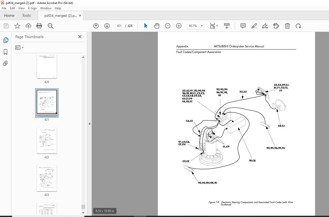
Code 52 6-94
Code 53 6-95
xiii PDMM-0067
Table of Contents MITSUBISHI Orderpicker Service Manual
Code 59 6-96
Code 91 6-97
Code 92 6-98
Code 93 6-100
Code 94 6-101
Code 96 6-101
Code 9C 6-102
Code 9E 6-102
Code 9F
Code 9H
Code 9J
Code 9K
Code 9L
Code CO
Code Cl
Code C2
Code C3
Code CS
Code C6
Code CS
Code C9
Code CA
Code CC
Code CE
Code CF
Code CJ
Code CL
Code CP
Code CU
Code CY
Code EC
Code Fl
Code F2
Code F3
Code F7
Code F9
Code FA
Code FB
Code FC
Analog Input Tests 6-129
Test A50 – Steer Controller Power Supply Voltage 6-129
Test A51 – Steer Controller Battery Sense Voltage 6-130
Test A52 – Maximum Drive Unit Rotation 6-131
Test A53 – Display Left Tractor Guidance Coil Voltage 6-132
Test A54 – Display Right Tractor Guidance Coil Voltage 6-134
Test A55 – Display Load Left Guidance Coil Voltage 6-135
Test A56 – Display Right Guidance Coil Voltage 6-136
PDMM-0067 xiv
MITSUBISHI Orderpicker Service Manual Table of Contents
Test A57 – Display Tractor Near Wire Coil Voltage 6-137
Test A58 – Display Load Near Wire Coil Voltage 6-138
Test A59 – Display Average Distance from Guide Wire 6-139
Test A60 – Display Peak Distance from Guide Wire 6-140
Test A61 – Display Average Heading Angle Magnitude 6-141
Test A62 – Display Peak Heading Angle 6-142
Test A63 – Display Average Guide Wire Signal Strength 6-143
Test A64 – Steer Input Encoder 6-144
Digital Input Tests 6-145
Test 150 – Display Auto/Manual Switch Position 6-146
Test 151 – Drive Unit Position Encoder Count 6-147
Test 152 – Steer Feedback Connector 6-148
Test 153 – Wire Guidance Board Status 6-149
Test 154 – Home Position Switch6-150
Test 155 – Display Channel A of Steer Encoder 6-151
Test 156 – Display Channel B of Steer Encoder 6-152
Test 157 – Home Proximity Switch Connection 6-153
Test 158 – Brake Deadman Switch (S2) 6-154
Test 159 – Steer Input Encoder Connection 6-155
Test 162 – Speed Proximity Connection 6-156
Test 163 – Speed Proximity Connection 6-157
Test 166 – Rail Switch Input 6-158
Test 168 – Rail Switch Connection 6-159
Digital Output Tests 6-160
Test 050 – Display LEDs6-160
Test 051 – Audible Alarm 6-161
Test 052 – Toggle ESTOP Output 6-162
Test 053 – Toggle Wire Guidance Speed Limit Output 6-163
Test 054 – Toggle Speed Limit Output 6-164
Appendix7 -1
Lubrication Equivalency Chart7 -2
Standard Torque Data For Bolts 7 -4
Conversion Table
DESCRIPTION:
Mitsubishi Forklift Truck EOP15 EOP24 EOP15P EOP24P Service Manual P.NO WENB8560-01 – PDF DOWNLOAD
Manual Overview:
G.B 27/01/25