Mitsubishi 2007 Lancer X Service Manual – PDF DOWNLOAD
$37.95
Mitsubishi 2007 Lancer X Service Manual – PDF DOWNLOAD
Description
Mitsubishi 2007 Lancer X Service Manual – PDF DOWNLOAD
FILE DETAILS:
Mitsubishi 2007 Lancer X Service Manual – PDF DOWNLOAD
Language : English
Pages : 2380
Downloadable : Yes
File Type : PDF
IMAGES PREVIEW OF THE MANUAL:
TABLE OF CONTENTS:
Mitsubishi 2007 Lancer X Service Manual – PDF DOWNLOAD
GENERAL 1
HOW TO USE THIS MANUAL 2
PRECAUTIONS BEFORE SERVICE 2
PROTECTING THE VEHICLE 2
DOING SERVICE WORK IN GROUPS OF TWO OR MORE MECHANICS 2
REMOVAL AND DISASSEMBLY 2
SPECIAL TOOLS 3
PARTS TO BE REPLACED 3
PARTS 3
TUBES AND OTHER RUBBER PARTS 3
LUBRICANTS 3
BRAKE FLUID 4
SERVICING THE ELECTRICAL SYSTEM 4
APPLICATION OF ANTI-CORROSION AGENTS AND UNDERCOATS 4
PRE-INSPECTION CONDITION 4
VEHICLE WASHING 4
MULTI USE TESTER (M U T -III) SUB ASSEMBLY 5
IN ORDER TO PREVENT VEHICLES FROM FIRE 5
ENGINE OILS 5
HEALTH WARNING 5
RECOMMENDED PRECAUTIONS 5
PRE-DELIVERY INSPECTION 7
NOTES CONCERNING ENTRIES 9
PAINTWORK TERMS 11
FIRST STEP 12
1 CONNECTION OF DARK CURRENT CONNECTOR 12
CONNECTING PROCEDURE 12
BODY 12
2 WRAP FILM 12
REMOVAL PROCEDURE 13
3 EXTERIOR 14
4 OPERATION OF DOOR LOCKING SYSTEMS AND DOOR HINGES 14
5 OPERATION OF DOOR MIRRORS, WINDOWS AND SUNROOF 14
UNDER HOOD 15
6 ENGINE OIL LEVEL 15
7 BRAKE MASTER CYLINDER FLUID LEVEL 15
8 CLUTCH MASTER CYLINDER FLUID LEVEL 15
9 WASHER FLUID LEVEL 15
10 BATTERY CONDITION AND CONNECTIONS 16
11 POWER STEERING FLUID LEVEL 16
12 ELECTRICAL WIRING 16
UNDER VEHICLE 16
13 TYRE AND SPARE TYRE PRESSURES 16
14 SUSPENSION SYSTEM 17
REMOVE FRONT SPRING RESTRAINTS 17
15 STEERING LINKAGE AND SPLIT PINS 17
16 UNDER BODY 17
BEFORE ROAD TEST 18
17 SEAT ADJUSTERS AND SEATBACK LATCHES 18
18 INHIBITOR SWITCH 18
19 IDLE CONTROL KNOB 18
20 INSTRUMENT PANEL CONTROLS 18
21 METERS, GAUGES, WARNING LAMPS AND INDICATION LAMPS 18
22 AIR CONDITIONER, HEATER AND DEFROSTER SYSTEM 18
23 WIPERS AND WASHERS 19
24 OPERATION OF SERVICE BRAKES AND PARKING BRAKES 19
25 CLUTCH OPERATION 19
26 OPERATION OF SEAT BELTS, SHOULDER BELTS AND RETRACTORS 20
ROAD TEST 20
27 ENGINE PERFORMANCE AND EXHAUST GAS 20
28 TRANSMISSION IN ALL RANGES 20
29 BRAKES 21
30 STEERING CONTROL 21
31 VIBRATION AND RATTLES 21
32 ELECTRICAL EQUIPMENT 21
AFTER ROAD TEST 22
33 IDLE SPEED 22
34 IGNITION TIMING 22
35 RADIATOR COOLANT LEVEL 22
36 HOSES, FLUID LINES AND CONNECTIONS LOCATED UNDER HOOD 22
37 MANUAL TRANSMISSION AND TRANSFER (4WD) OIL LEVEL 22
38 AUTOMATIC TRANSMISSION FLUID LEVEL 23
39 ENGINE, TRANSMISSION, STEERING GEAR BOX AND DIFFERENTIAL FOR LEAKS 23
40 FRONT AND REAR DIFFERENTIAL OIL LEVELS 23
41 HOSES, FLUID LINES AND CONNECTIONS LOCATED UNDER VEHICLE 23
FINAL STEPS 24
42 HEADLAMP AIMING 24
43 EQUIPMENT 24
44 EXTERIOR AND INTERIOR 24
45 OWNER INSTRUCTIONS 24
PERIODIC INSPECTION AND MAINTENANCE 25
PERIODIC INSPECTION AND MAINTENANCE SCHEDULE 27
OPERATIONS INSIDE THE ENGINE COMPARTMENT 30
A1 CHECK V-BELT FOR CRACKS, FRAYING, WEAR, AND ADJUST ITS TENSION 30
V-BELT CONDITION 30
V-BELT TENSION 30
A2 CHECK INTAKE AIR HOSE FOR DAMAGE (vehicles with turbocharger) 32
A3 REPLACE ENGINE TIMING BELT (except vehicles with timing chain) 32
A4 CHECK OPERATION OF CRANKCASE EMISSION CONTROL SYSTEM 32
BREATHER HOSE 32
VENTILATION HOSE 32
POSITIVE CRANKCASE VENTILATION SYSTEM CHECK 32
PCV VALVE CHECK 33
A5 REPLACE SPARK PLUGS 33
A6 CHECK VALVE CLEARANCE (except vehicles with auto-lash adjuster) 33
VALVE CLEARANCE CHECK AND ADJUSTMENT <4A9> 33
A7 CHECK RADIATOR HOSES FOR DAMAGE AND PROPER CONNECTION 35
A8 CHECK ENGINE COOLANT LEVEL IN RESERVOIR 35
A9 CHANGE ENGINE COOLANT 35
REMOVAL OF ENGINE COOLANT FROM THE CYLINDER BLOCK DRAIN PLUG 36
A10 CHECK AIR CLEANER ELEMENT FOR CLOGGING AND DAMAGE 38
A11 REPLACE AIR CLEANER ELEMENT 38
A12 CHECK FLUID LEVEL IN BRAKE RESERVOIR AND CLUTCH RESERVOIR (for hydraulic type clutch) 38
A13 CHANGE BRAKE FLUID 38
MASTER CYLINDER BLEEDING 39
A14 CHECK BATTERY ELECTROLYTE LEVEL 39
A15 REPLACE FUEL FILTER 40
<4A9> 40
<BWC> 41
OPERATIONS UNDER THE VEHICLE 42
B1 CHECK SUSPENSION SYSTEM FOR DAMAGE AND LOOSENESS 42
B2 CHECK SUSPENSION ARM BALL JOINTS FOR PLAY, AND DUST COVERS FOR DAMAGE 43
LOWER ARM BALL JOINT AXIAL PLAY CHECK 43
DUST COVERS FOR DAMAGE 43
B3 CHECK DRIVESHAFT BOOTS FOR DAMAGE 43
B4 CHECK STEERING LINKAGE FOR DAMAGE AND LOOSE CONNECTIONS (including seals and boots) 43
B5 CHECK GEAR OIL LEVEL IN MANUAL TRANSMISSION 44
B6 CHANGE GEAR OIL IN MANUAL TRANSMISSION 44
B7 CHECK EXHAUST PIPE CONNECTIONS FOR GAS LEAKAGE, AND CHECK PIPE INSTALLATION 44
OPERATIONS INSIDE THE VEHICLE 45
C1 CHECK BRAKE PEDAL AND CLUTCH PEDAL FOR FREE PLAY 45
BRAKE PEDAL FREE PLAY 45
CLEARANCE BETWEEN BRAKE PEDAL AND FLOOR PANEL 45
CLUTCH PEDAL CHECK AND ADJUSTMENT 45
C2 CHECK PARKING BRAKE LEVER STROKE AND PLAY 46
C3 REPLACE AIR PURIFIER FILTER 47
OPERATIONS OUTSIDE THE VEHICLE 47
D1 CHECK UNEVEN TYRE WEAR 47
FRONT WHEEL ALIGNMENT 47
REAR WHEEL ALIGNMENT 48
D2 CHECK FRONT AND REAR WHEEL BEARINGS FOR PLAY 49
<Front> 49
<Rear> 49
D3 CHECK BRAKE HOSES AND PIPES FOR LEAKAGE 49
D4 CHECK BRAKE PADS AND DISCS FOR WEAR 50
BRAKE DISC RUN-OUT CHECK 50
D5 CHECK BRAKE SHOE LININGS AND DISCS FOR WEAR 50
BRAKE LINING THICKNESS CHECK 50
BRAKE DISC INSIDE DIAMETER CHECK 51
D6 CHECK FUEL HOSES AND PIPES FOR LEAKAGE OR DETERIORATION 51
OPERATIONS AFTER ENGINE IS WARMED UP 52
E1 CHECK FLUID LEVEL IN AUTOMATIC TRANSMISSION 52
E2 CHANGE AUTOMATIC TRANSMISSION FLUID 52
Specifications 52
CHANGE PROCEDURE 52
AUTOMATIC TRANSMISSION FLUID COOLER LINE FLUSHING 54
E3 CHANGE ENGINE OIL 54
<4A9> 54
<BWC> 55
E4 REPLACE ENGINE OIL FILTER 55
<4A9> 55
<BWC> 56
E5 CHECK ENGINE IDLING SPEED 56
<4A9> 56
<BWC> 57
E6 CHECK CO CONCENTRATION 57
OTHERS 58
F1 CHECK BODY CONDITION FOR DAMAGE 58
F2 ROAD TEST 58
GENERAL 2097
GENERAL 1871
HOW TO USE THIS MANUAL 1673
ABBREVIATIONS 606
TARGETS OF DEVELOPMENT 1884
PRODUCT FEATURES 801
STYLING 62
DRIVING PERFORMANCE 2091
COMFORT 749
SAFETY 438
TECHNICAL FEATURES 2024
DESIGN FEATURES 63
DESIGN FEATURES 1718
MANUAL TRANSAXLE 1909
CONTINUOUSLY VARIABLE TRANSAXLE (CVT) 66
SAFETY-ENHANCED FRONT SEATS 2115
OTHER SAFETY FEATURES 2031
ENHANCED DIAGNOSIS SYSTEM 293
ADAPTATION OF BOLTS AND NUTS WITH STABILIZER FOR COEFFICIENT OF FRICTION * 541
VEHICLE IDENTIFICATION 73
VEHICLE IDENTIFICATION CODE CHART PLATE 73
VEHICLE IDENTIFICATION NUMBER LIST 542
GENERAL DATA AND SPECIFICATIONS 518
GENERAL <ELECTRICAL> 1871
HARNESS CONNECTOR INSPECTION 786
CONNECTOR CONTINUITY AND VOLTAGE TEST 2154
IMPROPER TERMINAL ENGAGEMENT CHECK 780
CONNECTOR TERMINAL ENGAGEMENT AND DISENGAGEMENT 535
HOW TO DIAGNOSE 855
INSPECTION 1875
INSPECTION INSTRUMENTS 84
CHECKING FUSES 2054
CAUTIONS IN EVENT OF BLOWN FUSE 85
CHECKING SWITCHES 794
CHECKING RELAYS 1689
CABLES AND WIRES CHECK 2105
BATTERY HANDLING 752
GENERAL ELECTRICAL SYSTEM CHECK 89
STEP 1 Remove the blown fuse and connect the test light across the fuse terminals (Circuit switch: OFF) 1879
STEP 2 Turn the switch ON and disconnect the illumination light connector 651
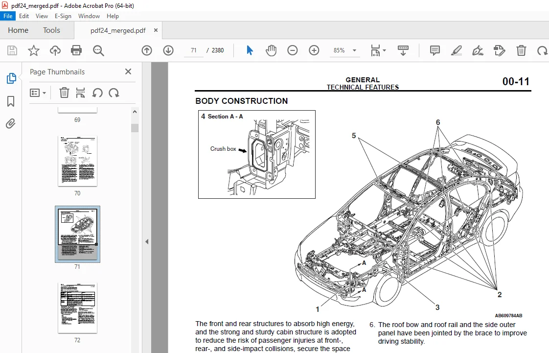
BODY CONSTRUCTION 2097
BODY COMPONENTS 120
BODY MAIN CROSS-SECTIONAL VIEWS 2025
MAINTENANCE, SERVICEABILITY 848
FENDER SHIELD 1020
SIDE STRUCTURE 2105
SIDE OUTER PANEL 1685
BODY CONSTRUCTION CHARACTERISTICS 2027
HEADLIGHT SUPPORT 1110
FENDER SHIELD 2105
FRONT SIDEMEMBER REINFORCEMENT 822
FRONT DECK 1892
DASH PANEL 2116
SIDE STRUCTURE 106
SIDE STRUCTURE REINFORCEMENT 2037
FRONT FLOOR 111
REAR FLOOR 2086
REAR FLOOR SIDEMEMBER REINFORCEMENT 2087
SILENCER APPLICATION LOCATIONS 116
FOAMING MATERIAL USAGE LOCATIONS 117
BODY DIMENSIONS 2097
BODY DIMENSIONS AND MEASUREMENT METHODS 787
TYPE A (PROJECTED DIMENSIONS) 122
TYPE B (ACTUAL-MEASUREMENT DIMENSIONS) 793
WELDED PANEL REPLACEMENT 2097
ULTRA HIGH STRENGTH STEEL PLATE 778
ADVANTAGES OF ULTRA HIGH STRENGTH STEEL PLATE 146
PRECAUTION UPON MAINTENANCE OF ULTRA HIGH STRENGTH STEEL PLATE 351
FRONT END CROSSMEMBER 748
FENDER SHIELD 534
NOTE ON REPAIR WORK 151
FRONT SIDEMEMBER (PARTIAL REPLACEMENT) 1681
FRONT PILLAR 2050
NOTE ON REPAIR WORK 776
FRONT PILLAR (PARTIAL REPLACEMENT) 1884
NOTE ON REPAIR WORK 2052
CENTER PILLAR 846
NOTE ON REPAIR WORK 936
SIDE SILL 2105
NOTE ON REPAIR WORK 2027
QUARTER OUTER 176
NOTE ON REPAIR WORK 2105
REAR END PANEL 861
REAR FLOOR 958
NOTE ON REPAIR WORK 1878
ROOF 182
QUARTER INNER 184
NOTE ON REPAIR WORK 1881
QUARTER INNER (PARTIAL REPLACEMENT) 1693
NOTE ON REPAIR WORK 189
FRONT DOOR OUTER PANEL (WELDED TYPE) 2114
FRONT DOOR OUTER PANEL (ADHESION TYPE) 915
NOTE ON REPAIR WORK 2115
REAR DOOR OUTER PANEL (WELDED TYPE) 1890
REAR DOOR OUTER PANEL (ADHESION TYPE) 2115
NOTE ON REPAIR WORK 193
SYNTHETIC-RESIN PARTS 1871
LOCATION OF SYNTHETIC-RESIN PARTS 196
BODY COLOR 1871
BODY COLOR CODE 814
BODY COLOR CHARTS 574
BODY COLORING 1872
BASE OF BODY REPAIR 1871
GENERAL 2073
WELDING 854
FUSION WELDING 204
PRESSURE WELDING 1674
BRAZING 1669
ADVANTAGES OF ELECTRIC RESISTANCE SPOT WELDING 204
PLUG WELDING 1836
CONTINUOUS WELDING 213
NOTES REGARDING MIG WELDING 822
BRAZING 214
Notes with regard to brazing work 807
GAS WELDING 2115
BODY REPAIR 1891
STANDARD PROCEDURES FOR REPLACEMENT OF WELDED PANELS 961
CAUTIONS REGARDING BODY REPAIR 670
THEFT PROTECTION 224
PANEL REPAIR CAUTION 2083
HOW TO PEEL OFF THE SURFACE MASKING FILM FROM THE THEFT-PROTECTION LABEL 1061
REPAIRS USING A HAMMER AND DOLLY 228
OVERALL ROUGH REPAIRS 229
FRAME STRAIGHTENING NOTES 848
CHECKING FOR FRAME CRACKING OR FLAKING 2085
REPAIRING CRACKS 1076
NOTES REGARDING REPAIR WORK 1901
SAFETY MEASURES 233
HEALTH AND SANITATION PROCEDURES 1708
VEHICLE PROTECTION 2039
CORROSION PROTECTION 983
ZINC PHOSPHATE COATING 488
BODY SEALING 2042
UNDERBODY COATING 613
WAX INJECTION 241
SEALING TAPE 707
ANTICORROSION TREATMENT AT THE TIME OF BODY REPAIR WORK 488
CORROSION PROTECTION FOR HOLLOW PARTS 1085
ANTICORROSION TREATMENT OF ROUGH CUTS 242
SPOT SEALER 772
BODY SEALING 1914
REPAIR OF SYNTHETIC-RESIN PARTS 2044
REPAIR JUDGMENT 1915
REPAIR PROCEDURE 2045
ENGINE 2097
ENGINE MECHANICAL 1871
GENERAL DESCRIPTION 1871
BASE ENGINE 255
VALVE SEATS 846
VALVE GUIDES 353
ENGINE MECHANICAL 2097
GENERAL INFORMATION 2091
ENGINE DIAGNOSIS 1872
SERVICE SPECIFICATIONS 274
SEALANTS 784
SPECIAL TOOLS 1689
ON-VEHICLE SERVICE 1694
DRIVE BELT TENSION CHECK 1694
AUTO-TENSIONER CHECK 2115
OPERATION CHECK 279
FUNCTION CHECK 824
VALVE CLEARANCE CHECK AND ADJUSTMENT 281
IGNITION TIMING CHECK 1893
CURB IDLE SPEED CHECK 963
IDLE MIXTURE CHECK 1896
COMPRESSION PRESSURE CHECK 286
MANIFOLD VACUUM CHECK 287
CRANKSHAFT PULLEY 2119
REMOVAL SERVICE POINTS 2038
INSTALLATION SERVICE POINT 2039
CAMSHAFT 1064
REMOVAL SERVICE POINTS 2042
INSTALLATION SERVICE POINTS 300
VALVE STEM SEAL 992
REMOVAL SERVICE POINTS 309
INSTALLATION SERVICE POINTS 1752
OIL PAN 315
REMOVAL SERVICE POINTS 316
INSTALLATION SERVICE POINTS 632
INSPECTION 318
CRANKSHAFT OIL SEAL 319
REMOVAL SERVICE POINT 320
INSTALLATION SERVICE POINTS 392
CYLINDER HEAD GASKET 323
REMOVAL SERVICE POINTS 326
INSTALLATION SERVICE POINTS 1110
TIMING CHAIN 333
REMOVAL SERVICE POINTS 334
INSTALLATION SERVICE POINTS 337
OIL PUMP CHAIN 1954
REMOVAL SERVICE POINT 1956
INSTALLATION SERVICE POINTS 341
OIL PUMP 1956
REMOVAL SERVICE POINT 343
ENGINE ASSEMBLY 344
REMOVAL SERVICE POINTS 346
INSTALLATION SERVICE POINTS 1967
ENGINE OVERHAUL 2097
GENERAL SPECIFICATIONS 2098
SERVICE SPECIFICATIONS 1674
FASTENER TIGHTENING SPECIFICATIONS 752
NEW TIGHTENING METHOD BY USING PLASTIC REGION TIGHTENING BOLT 1700
SEALANTS AND ADHESIVES 1898
SPECIAL TOOLS 1898
GENERATOR AND IGNITION SYSTEM 2038
REMOVAL SERVICE POINT 973
INSTALLATION SERVICE POINTS 833
THROTTLE BODY AND EGR SYSTEM 2039
INSTALLATION SERVICE POINTS 365
INTAKE MANIFOLD AND FUEL SYSTEM 2041
INSTALLATION SERVICE POINTS 368
EXHAUST MANIFOLD 371
<For except CALIFORNIA> 371
<For CALIFORNIA> 712
INSTALLATION SERVICE POINTS 1917
WATER HOSE AND PIPE 374
INSTALLATION SERVICE POINTS 375
OIL PAN AND TIMING CHAIN CASE 376
REMOVAL SERVICE POINTS 1923
INSTALLATION SERVICE POINTS 378
TIMING CHAIN 382
REMOVAL SERVICE POINTS 1002
INSTALLATION SERVICE POINTS 384
INSPECTION 493
CAMSHAFT 2367
REMOVAL SERVICE POINTS 390
INSTALLATION SERVICE POINTS 390
INSPECTION 392
CYLINDER HEAD AND VALVES 1015
REMOVAL SERVICE POINTS 396
INSTALLATION SERVICE POINTS 397
INSPECTION 399
REPAIR PROCEDURE OF VALVE SEAT 1795
REPLACEMENT PROCEDURE OF VALVE SEAT 1945
REPLACEMENT PROCEDURE OF VALVE GUIDE 402
OIL PUMP CHAIN 403
REMOVAL SERVICE POINTS 1115
INSTALLATION SERVICE POINTS 405
PISTON AND CONNECTING ROD 409
REMOVAL SERVICE POINTS 410
INSTALLATION SERVICE POINTS 411
INSPECTION 416
CRANKSHAFT AND CYLINDER BLOCK 418
REMOVAL SERVICE POINT 418
INSTALLATION SERVICE POINTS 419
INSPECTION 423
ENGINE LUBRICATION 1871
GENERAL DESCRIPTION 931
OIL PASSAGE 946
OIL FILTER 2072
OIL PAN 1884
OIL DIPSTICK, OIL FILLER CAP, OIL DRAIN PLUG 428
OIL PUMP 947
FUEL 1871
FUEL 2097
MULTIPORT FUEL SYSTEM (MFI) 1871
GENERAL DESCRIPTION 1071
System Block Diagram 2073
<Except for California> 2091
<California> 2052
CONTROL UNIT 855
SENSOR 861
ACTUATOR 455
INJECTOR 455
THROTTLE ACTUATOR CONTROL MOTOR 2080
IGNITION COIL 2080
EXHAUST GAS RECIRCULATION (EGR) VALVE 682
EVAPORATIVE EMISSION PURGE SOLENOID 918
INTAKE ENGINE OIL CONTROL VALVE 682
EXHAUST ENGINE OIL CONTROL VALVE 755
EVAPORATIVE EMISSION VENTILATION SOLENOID 1696
GENERATOR G TERMINAL 1697
FUEL INJECTION CONTROL 2116
System Configuration Diagram 542
1 INJECTOR ACTUATION (FUEL INJECTION) TIMING 2081
Fuel Injection During Cranking and Normal Operation 2116
Additional Fuel Injection During Acceleration 581
2 Fuel injection volume (injector drive time) control 1057
Fuel Injection Volume Control Block Diagram 2036
IGNITION TIMING AND CONTROL FOR CURRENT CARRYING TIME 921
System Configuration Diagram 2036
1 Ignition distribution control 670
2 Spark-advance control and current carrying time control 469
THROTTLE VALVE OPENING ANGLE CONTROL AND IDLE SPEED CONTROL 922
While starting 1061
While idling 470
While driving 470
Initialize control 2037
MIVEC (Mitsubishi Innovative Valve Timing Electronic Control System) 2084
System Configuration Diagram 599
Phase Angle Detection 829
The detected phase angle is calculated using the cam position sensor signal 1062
MULTIPORT FUEL INJECTION (MFI) RELAY CONTROL 1900
FUEL PUMP RELAY CONTROL 2085
STARTER RELAY CONTROL 2120
HEATED OXYGEN SENSOR HEATER CONTROL 481
A/C COMPRESSOR RELAY CONTROL 482
GENERATOR CONTROL 971
EVAPORATIVE EMISSION CONTROL SYSTEM INCORRECT PURGE FLOW MONITOR 926
EXHAUST GAS RECIRCULATION CONTROL 1077
CONTROLLER AREA NETWORK (CAN) 973
EVAPORATIVE EMISSION PURGE CONTROL 485
HC TRAP CATALYTIC CONVERTER DETERIORATION MONITOR 2085
ON-BOARD DIAGNOSTICS 485
FUEL SUPPLY 1871
GENERAL INFORMATION 1871
CONSTRUCTION DIAGRAM 810
FUEL TANK 1884
CONSTRUCTION DIAGRAM 1872
ENGINE COOLING 2097
GENERAL INFORMATION 2091
CONSTRUCTION DIAGRAM 2091
SERVICE SPECIFICATIONS 2091
COOLANT 584
SEALANT 503
ENGINE COOLING DIAGNOSIS 535
SYMPTOM PROCEDURES 791
Inspection Procedure 1: Coolant Leak 504
DIAGNOSIS 1044
STEP 1 Check for coolant leaks 1885
STEP 2 Retest the system 1072
Inspection Procedure 2: Engine Overheating 2074
DIAGNOSIS 1875
STEP 1 Remove the radiator cap and check for coolant contamination 640
STEP 2 Check the radiator cap valve opening pressure 581
STEP 3 Check thermostat operation 1886
STEP 4 Check the drive belt for slippage or damage 2104
STEP 5 Retest the system 2054
Inspection Procedure 3: Radiator Fan and Condenser Fan do not Operate 2026
DIAGNOSIS PROCEDURE 1687
STEP 1 M U T -III other system diagnosis codes 958
STEP 2 Check the cooling fan relay 562
STEP 3 Connectors check: A-23X condenser fan relay connector, A-26X radiator fan relay connector and A-28X fan control relay connector 1689
STEP 4 Check the cooling fan motor 2028
STEP 5 Connectors check: A-40 condenser fan motor connector and A-35 radiator fan motor connector 2077
STEP 6 Measure the voltage at radiator fan relay connector A-26X 911
STEP 7 Check the harness between radiator fan relay connector A-26X (terminal 3, 4) and fusible link number 29 805
STEP 8 Measure the voltage at fan control relay connector A-28X 958
STEP 9 Check the harness between fan control relay connector A-28X (terminal 1) and fusible link number 28 1889
STEP 10 Measure the voltage at condenser fan relay connector A-23X 959
STEP 11 Check the harness between condenser fan relay connector A-23X (terminal 1, 4) and fusible link number 28 509
STEP 12 Check the harness between radiator fan relay connector A-26X (terminal 2) and radiator fan motor connector A-35 (terminal 1) 913
STEP 13 Check the harness between fan control relay connector A-28X (terminal 5) and radiator fan motor connector A-35 (terminal 2) 753
STEP 14 Measure the resistance at fan control relay connector A-28X 822
STEP 15 Check the harness between fan control relay connector A-28X (terminal 4) and earth 806
STEP 16 Check the harness between fan control relay connector A-28X (terminal 2) and condenser fan relay connector A-23X (terminal 3) 753
STEP 17 Check the harness between condenser fan relay connector A-23X (terminal 3) and condenser fan motor connector A-40 (terminal 1) 862
STEP 18 Measure the resistance at condenser fan motor connector A-40 510
STEP 19 Check the harness between condenser fan motor connector A-40 (terminal 2) and earth 1890
STEP 20 Check the harness between ETACS-ECU connector C-312 (terminal 2) and radiator fan relay connector A-26X (terminal 1) 2031
STEP 21 Check the harness between ETACS-ECU connector C-312 (terminal 9) and fan control relay connector A-28X (terminal 3) 2115
STEP 22 Check the harness between ETACS-ECU connector C-312 (terminal 8) and condenser fan relay connector A-23X (terminal 2) 511
STEP 23 M U T -III actuator test 1694
STEP 24 Retest the system 2065
SPECIAL TOOLS 1892
ON-VEHICLE SERVICE 943
ENGINE COOLANT LEAK CHECK 512
RADIATOR CAP OPENING PRESSURE CHECK 2080
ENGINE COOLANT CHANGE 2034
ENGINE COOLANT CONCENTRATION TEST 514
COOLING FAN RELAY CONTINUITY CHECK 683
COOLING FAN MOTOR CHECK 2082
THERMOSTAT 1061
REMOVAL SERVICE POINT 2037
INSTALLATION SERVICE POINTS 1898
INSPECTION 520
WATER PUMP 2119
WATER HOSE AND WATER PIPE 1705
REMOVAL SERVICE POINTS 692
INSTALLATION SERVICE POINTS 524
INSPECTION 525
Water Pipe and Hose Check 525
RADIATOR 929
REMOVAL SERVICE POINT 1913
INSTALLATION SERVICE POINT 528
ENGINE COOLING 1871
GENERAL INFORMATION 2098
CONSTRUCTION DIAGRAM 530
WATER PASSAGE 1872
WATER PUMP 531
INTAKE AND EXHAUST 2097
GENERAL DESCRIPTION 534
SERVICE SPECIFICATION 2091
INTAKE AND EXHAUST DIAGNOSIS 2091
SYMPTOM PROCEDURES 535
Inspection Procedure 1: Exhaust Leakage 818
DIAGNOSIS 1672
STEP 1 Start the engine Have an assistant stay in the driver’s seat Raise the vehicle on a hoist Have the assistant rev th 799
STEP 2 Check the gasket for cracks, damage 1672
STEP 3 Check for loosening in each coupling section 2023
Inspection Procedure 2: Abnormal Noise 902
DIAGNOSIS 679
STEP 1 Start the engine Have an assistant stay in the drivers seat Raise the vehicle on a hoist Have the assistant rev the engine while searching for exhaust leaks 779
STEP 2 Check for missing parts in the muffler Tap the muffler lightly to check for loose baffles, etc 2103
STEP 3 Check the hanger for cracks 535
STEP 4 Check for interference of the pipes and muffler with the body 1674
STEP 5 Check the heat protectors 846
STEP 6 Check the pipes and muffler for damage 855
SPECIAL TOOL 2073
AIR CLEANER 819
INTAKE MANIFOLD 537
REMOVAL SERVICE POINT 822
INSTALLATION SERVICE POINTS 2078
INSPECTION 540
EXHAUST MANIFOLD 541
<Except for CALIFORNIA> 2079
<Vehicles for CALIFORNIA> 542
REMOVAL SERVICE POINT 2081
INSTALLATION SERVICE POINT 944
INSPECTION 597
EXHAUST PIPE AND MAIN MUFFLER 2116
REMOVAL SERVICE POINTS 1877
INSTALLATION SERVICE POINTS 1063
INTAKE AND EXHAUST 1871
AIR DUCT AND AIR CLEANER 818
CONSTRUCTION DIAGRAM 1672
INTAKE MANIFOLD 2072
EXHAUST MANIFOLD 1666
EXHAUST PIPE AND MUFFLER 550
CONSTRUCTION DIAGRAM 902
ENGINE ELECTRICAL 1871
STARTER MOTOR 2072
ALTERNATOR 1666
IGNITION COIL 552
SPARK PLUG 955
ENGINE AND EMISSION CONTROL 1871
ENGINE CONTROL 556
CONSTRUCTION DIAGRAM 1041
AUTO-CRUISE CONTROL SYSTEM 2100
CONSTRUCTION DIAGRAM 1673
SYSTEM OUTLINE 979
BLOCK DIAGRAM 793
SYSTEM FUNCTIONS 936
EMISSION CONTROL 909
<Except for California> 680
<California> 1689
POSITIVE CRANKCASE VENTILATION (PCV) VALVE 565
EVAPORATIVE EMISSION PURGE SOLENOID 611
EXHAUST GAS RECIRCULATION (EGR) VALVE 806
1 AIR-FUEL RATIO FEEDBACK CONTROL 568
2 CATALYTIC CONVERTER 1693
3 HC TRAP CATALYTIC CONVERTER <California> 568
HEATED OXYGEN SENSOR (3RD) 2079
HC TRAP CATALYTIC CONVERTER DETERIORATION MONITOR 1056
CLUTCH 2097
CLUTCH 1871
GENERAL INFORMATION 578
CONSTRUCTION DIAGRAM 1872
CONCENTRIC SLAVE CYLINDER 1071
CLUTCH OVERHAUL 2097
SPECIFICATIONS 2090
CLUTCH 814
INSTALLATION SERVICE POINTS 1872
CLUTCH INSPECTION 1046
MANUAL TRANSAXLE 1871
MANUAL TRANSAXLE 2098
TRANSAXLE CONTROL 2091
MANUAL TRANSAXLE 2097
MANUAL TRANSAXLE OVERHAUL 2097
GENERAL SPECIFICATIONS 2091
SERVICE SPECIFICATIONS 2022
ADJUSTING SNAP RINGS AND SPACERS 591
FASTENER TIGHTENING SPECIFICATIONS 2056
SEALANTS AND ADHESIVES 2030
LUBRICANTS 961
SPECIAL TOOLS 2079
TRANSAXLE 599
DISASSEMBLY SERVICE POINTS 602
ADJUSTMENT BEFORE ASSEMBLY 603
ASSEMBLY SERVICE POINTS 605
INSPECTION 612
INPUT SHAFT 2042
DISASSEMBLY SERVICE POINTS 614
ASSEMBLY SERVICE POINTS 614
OUTPUT SHAFT 1917
DISASSEMBLY SERVICE POINTS 618
ASSEMBLY SERVICEPOINTS 2282
SELECT LEVER 997
ASSEMBLY SERVICE POINTS 727
CLUTCH HOUSING 1092
DISASSEMBLY SERVICE POINTS 647
ASSEMBLY SERVICE POINTS 627
TRANSAXLE CASE 1094
DISASSEMBLY SERVICE POINTS 1005
ASSEMBLY SERVICE POINTS 632
DIFFERENTIAL 634
DISASSEMBLY SERVICE POINTS 635
ASSEMBLY SERVICE POINTS 1932
CVT 2097
CONTINUOUSLY VARIABLE TRANSAXLE (CVT) 1871
CVT 819
SYSTEM CONFIGURATION 793
OVERVIEW 1876
DESCRIPTION OF STRUCTURE AND OPERATION 644
STEEL BELT 958
TRANSMISSION FLUID WARMER (TRANSMISSION FLUID COOLER) 649
TRANSMISSION FLUID FILTER 681
OIL PRESSURE CONTROL SYSTEM 654
ELECTRONIC CONTROL SYSTEM 2066
CONTROL SYSTEM DIAGRAM 663
INVECS-III 943
RATIO PATTERN 2116
<D RANGE> 666
<L RANGE (VEHICLES WITHOUT SPORT MODE)> 1894
<SPORT MODE (VEHICLES WITH SPORT MODE)> 668
NORMAL HYDRAULIC CONTROL 2036
SECONDARY PRESSURE FEEDBACK CONTROL 669
ENGINE AND CVT INTEGRATED CONTROL (CAN COMMUNICATION CONTROL) 670
DIAGNOSTIC FUNCTION 670
FAIL-SAFE FUNCTION 670
TRANSAXLE CONTROL 672
CVT ERRONEOUS OPERATION PREVENTION MECHANISMS 1061
STRUCTURE OF SHIFT LOCK SYSTEM 674
SHIFT LOCK CIRCUIT 674
OPERATIONAL DESCRIPTION 829
CONTINUOUSLY VARIABLE TRANSAXLE OVERHAUL 2097
GENERAL INFORMATION 2072
SPECIFICATIONS 2072
SPECIAL TOOLS 862
TRANSAXLE 2118
ASSEMBLY SERVICE POINT 707
FORWARD CLUTCH 733
DISASSEMBLY SERVICE POINT 734
REASSEMBLY SERVICE POINT 735
INSPECTION 736
FORWARD CLUTCH SUB-ASSEMBLY 736
INPUT SHAFT AND INTERNAL GEAR 736
REDUCTION GEAR 737
DISASSEMBLY SERVICE POINT 738
ASSEMBLY SERVICE POINT 739
INSPECTION 740
REDUCTION GEAR SUB-ASSEMBLY 1934
ASSEMBLY SERVICE POINT 741
DIFFERENTIAL 1104
DISASSEMBLY SERVICE POINT 1013
REASSEMBLY SERVICE POINT 743
INSPECTION 744
DIFFERENTIAL SUB-ASSEMBLY 745
ASSEMBLY SERVICE POINT 745
FRONT AXLE 2097
GENERAL INFORMATION 748
SPECIFICATIONS 749
FRONT AXLE DIAGNOSIS 1884
SYMPTOM PROCEDURES 1875
INSPECTION PROCEDURE 1: Noise during Wheel Rotation 2052
DIAGNOSIS 2094
STEP 1 Check the wheel bearing end play 2094
STEP 2 Check the driveshaft and inner shaft for bending 750
STEP 3 Check the center bearing for wear 803
STEP4 Check the driveshaft assembly for wear or damage 2105
STEP 5 Retest the system 2105
INSPECTION PROCEDURE 2: Noise Due to Excessive Play of Wheel in Turning Direction 751
DIAGNOSIS 803
STEP 1 Check for play in the inner shaft and side gear serration, the driveshaft and side gear serration, or the driveshaft and front hub serration 751
STEP 2 Retest the system 1877
SPECIAL TOOLS 751
ON-VEHICLE SERVICE 754
WHEEL BEARING END PLAY CHECK 2062
HUB BOLT REPLACEMENT 2031
FRONT AXLE HUB ASSEMBLY 862
REMOVAL SERVICE POINTS 2081
INSTALLATION SERVICE POINTS 758
INSPECTION 758
DISASSEMBLY SERVICE POINTS 1899
ASSEMBLY SERVICE POINTS 761
INSPECTION 972
DRIVESHAFT ASSEMBLY 926
REMOVAL SERVICE POINTS 1078
INSTALLATION SERVICE POINTS 767
DISASSEMBLY SERVICE POINTS 769
ASSEMBLY SERVICE POINTS 919
INSPECTION 2059
EBJ BOOT REPLACEMENT 2043
REAR AXLE 1871
GENERAL INFORMATION 1871
REAR AXLE 2097
GENERAL INFORMATION 778
SPECIFICATIONS 2072
REAR AXLE DIAGNOSIS 778
SYMPTOM PROCEDURES 2049
INSPECTION PROCEDURE 1: Abnormal Noise 779
DIAGNOSIS 2072
STEP 1 Check the rear hub assembly installation bolts for looseness 843
STEP 2 Check the wheel bearing end play 1673
STEP 3 Check the rear hub rotary-sliding resistance 780
STEP 4 Retest the systems 2091
SPECIAL TOOLS 780
ON-VEHICLE SERVICE 781
WHEEL BEARING END PLAY CHECK 1875
REAR HUB ROTARY-SLIDING RESISTANCE CHECK 781
HUB BOLT REPLACEMENT 782
REAR AXLE HUB ASSEMBLY 783
REMOVAL SERVICE POINT 2058
INSPECTION 784
WHEEL AND TIRE 1871
GENERAL INFORMATION 931
SPECIFICATIONS 786
TIRE PRESSURE MONITORING SYSTEM (TPMS) 786
WHEEL AND TIRE 2097
WHEEL AND TIRE DIAGNOSIS 2097
PURPOSE 789
PROCEDURE <Balancing Tips> 946
<Confirming Proper Balance> 854
<Wheel Balancer Calibration Checks> 905
ON-VEHICLE SERVICE 1885
TIRE INFLATION PRESSURE CHECK 1675
TIRE WEAR CHECK 950
WHEEL RUNOUT CHECK 2091
WHEEL AND TIRE 793
INSTALLATION SERVICE POINT 793
TIRE PRESSURE MONITORING SYSTEM (TPMS) 2104
SPECIFICATIONS 2074
POWER PLANT MOUNT 1871
GENERAL INFORMATION 1871
POWER PLANT MOUNT 2097
GENERAL INFORMATION 798
SPECIAL TOOLS 798
ENGINE MOUNTING 817
INSTALLATION SERVICE POINT 2103
TRANSAXLE MOUNTING 801
REMOVAL SERVICE POINT 2052
INSTALLATION SERVICE POINTS 2025
ENGINE ROLL STOPPER AND CENTERMEMBER 819
INSTALLATION SERVICE POINT 1073
CROSSMEMBER 2028
REMOVAL SERVICE POINTS 2079
INSTALLATION SERVICE POINT 1694
FRONT SUSPENSION 1871
GENERAL INFORMATION 2072
SPECIFICATIONS 810
REAR SUSPENSION 1871
GENERAL INFORMATION 1871
SPECIFICATIONS 818
REAR SUSPENSION 2097
GENERAL INFORMATION 818
SPECIFICATIONS 818
REAR SUSPENSION DIAGNOSIS 937
SYMPTOM PROCEDURES 2076
INSPECTION PROCEDURE 1: Squeaks or other Abnormal Noise 820
STEP 1 Check for loose rear suspension installation bolts and nuts 2056
STEP 2 Check the malfunction of shock absorbers (worn bushings) 2056
STEP 3 Check the upper arms and/or lower arms and/or control links for deformity or damage 2027
STEP 4 Check the trailing arms for deformity or damage 2028
STEP 5 Retest the system 820
INSPECTION PROCEDURE 2: Poor Ride 2058
STEP 1 Check the excessive tire inflation pressure 2105
STEP 2 Check for malfunction of shock absorbers (weak or broken springs) 2105
STEP 3 Check the stabilizer bar and/or stabilizer links for deformity or damage 911
STEP 4 Retest the system 1690
INSPECTION PROCEDURE 3: Body Tilting 821
STEP 1 Check for weak or deteriorated bushings 821
STEP 2 Check for weak or broken springs 2029
STEP 3 Check the upper arms and/or lower arms and/or control links for deformity or damage 1073
STEP 4 Check the trailing arms for deformity or damage 821
STEP 5 Retest the system 821
SPECIAL TOOL 913
ON-VEHICLE SERVICE 823
REAR WHEEL ALIGNMENT CHECK AND ADJUSTMENT 2115
CAMBER 2115
STABILIZER LINK BALL JOINT DUST COVER INSPECTION 823
CONTROL LINK, UPPER ARM AND LOWER ARM 824
REMOVAL SERVICE POINT 943
INSTALLATION SERVICE POINTS 900
CONTROL LINK, UPPER ARM AND LOWER ARM INSPECTION 1057
LOWER ARM BUSHING REPLACEMENT 1058
TRAILING ARM 2081
REMOVAL SERVICE POINT 2119
INSPECTION 2084
TRAILING ARM BUSHING REPLACEMENT 829
SHOCK ABSORBER ASSEMBLY 832
INSTALLATION SERVICE POINT 833
INSPECTION 1063
DISASSEMBLY SERVICE POINT 2086
ASSEMBLY SERVICE POINTS 2087
STABILIZER BAR <GTS, ES> 2087
INSTALLATION SERVICE POINT 837
INSPECTION 837
STABILIZER LINK BALL JOINT ROTATION TORQUE CHECK 837
STABILIZER LINK BALL JOINT DUST COVER CHECK 978
REAR SUSPENSION CROSSMEMBER 838
REMOVAL SERVICE POINTS 839
INSPECTION 839
SERVICE BRAKE 1871
BASIC BRAKE SYSTEM 1871
GENERAL 844
FEATURES 2072
<Vehicles without ABS> 845
<Vehicles with ABS> 2051
CONSTRUCTION DESCRIPTION 1886
VARIABLE BOOST RATIO MECHANISM 848
FOUR-WHEEL ANTI-LOCK BRAKE SYSTEM (4ABS) 1871
GENERAL INFORMATION 1681
CONSTRUCTION DESCRIPTION 2052
ABS warning light, Brake warning light 2038
ABS control cycle 2076
INITIAL CHECK 2076
STARTUP CHECK 861
CONSTANT CHECK 2077
CAN COMMUNICATION 861
FAIL-SAFE FUNCTION 861
DIAGNOSTIC FUNCTION 2036
PARKING BRAKES 1871
GENERAL INFORMATION 1871
<Vehicles with rear drum brake> 1883
<Vehicles with rear disc brake> 931
POWER STEERING 1871
GENERAL INFORMATION 931
FEATURES 1699
STEERING WHEEL 869
STEERING SHAFT AND COLUMN 2024
IMPACT-ABSORBING MECHANISM 956
OIL PUMP 2025
STEERING GEAR 2074
OIL RESERVOIR 906
BODY 1871
BODY 1871
GENERAL DESCRIPTION 2051
FEATURES 2119
MAIN BODY 879
HOOD AND FENDER 885
FUEL FILLER LID 886
STRUT TOWER BAR <GTS> 958
DOOR 2028
DESCRIPTION OF CONSTRUCTION AND OPERATION 2105
DESCRIPTION OF CONSTRUCTION AND OPERATION 891
PROTECTOR FILM <Vehicles without side air dam> 894
TRUNK LID 915
WINDOW GLASS 896
SUNROOF 897
DESCRIPTION OF CONSTRUCTION AND OPERATION 2034
LOOSE PANELS 2116
CUSTOMIZATION FUNCTION 900
KEYLESS OPERATION SYSTEM (KOS) 1871
GENERAL INFORMATION 902
SYSTEM OPERATION 908
DESCRIPTION OF CONSTRUCTION AND OPERATION 908
DESCRIPTION OF CONSTRUCTION AND OPERATION 914
SECURITY ALARM 916
OPERATION 2033
ENGINE STARTING FUNCTION VALID AREA 2035
OPERATION 2035
TPMS WARNING LIGHT 921
TPMS TRANSMITTER (TIRE PRESSURE SENSOR) 1699
CONFIGURATION FUNCTION 927
WIRELESS CONTROL MODULE (WCM) 1871
GENERAL INFORMATION 1666
SYSTEM OPERATION 956
DESCRIPTION OF CONSTRUCTION AND OPERATION 2024
SECURITY ALARM 958
OPERATION 2076
OPERATION 939
TPMS WARNING LIGHT 940
TPMS TRANSMITTER (TIRE PRESSURE SENSOR) 1880
CONFIGURATION FUNCTION 1056
EXTERIOR 1871
GENERAL INFORAMATION 2072
FEATURES 946
BUMPER AND RADIATOR GRILLE 2051
CONSTRUCTION DIAGRAM 2079
AERO PARTS 2052
CONSTRUCTION DIAGRAM 2064
WINDSHIELD WIPER AND WASHER 950
CONSTRUCTION DIAGRAM 950
DESCRIPTION OF CONSTRUCTION AND OPERATION 951
DOOR MIRRORS 2076
CONSTRUCTION DIAGRAM 2115
CONFIGURATION FUNCTION 2028
EXTERIOR 2097
SPECIFICATIONS 2051
AERO PARTS 2073
FRONT BUMPER ASSEMBLY AND RADIATOR GRILLE 2052
DISASSEMBLY SERVICE POINT 2060
REASSEMBLY SERVICE POINT 1889
REAR BUMPER ASSEMBLY 960
GARNISHES AND MOLDINGS 961
REMOVAL SERVICE POINT 962
DOOR SASH TAPE 962
REMOVAL SERVICE POINT 963
INSTALLATION SERVICE POINT 1698
SIDE AIR DAM 967
REMOVAL SERVICE POINT 1897
INSTALLATION SERVICE POINT 968
REAR SPOILER 969
INSTALLATION SERVICE POINT 969
UNDER COVER 1062
WINDSHIELD WIPER AND WASHER 971
WINDSHIELD WIPER AND WASHER OPERATION 971
WINDSHIELD WIPER AND WASHER DIAGNOSIS 1078
SYMPTOM PROCEDURES 975
INSPECTION PROCEDURE 1: The windshield wipers do not work at all 977
DIAGNOSIS 978
STEP 1 Use the scan tool MB991958 to check if an ETACS-related diagnostic trouble code is set 1716
STEP 2 Check the input signal related to the windshield wiper operation 979
STEP 3 Check windshield wiper motor connector A-04 for loose, corroded or damaged terminals, or terminals pushed back in the connector 2182
STEP 4 Check the windshield wiper motor 1718
STEP 5 Check the ground circuit to the windshield wiper motor Measure the resistance at the windshield wiper motor connector A-04 1909
STEP 6 Check the wiring harness between windshield wiper motor connector A-04 (terminal 2) and ground 1082
STEP 7 Check ETACS-ECU connector C-304 for loose, corroded or damaged terminals, or terminals pushed back in the connector 1720
STEP 8 Measure the voltage at ETACS-ECU connector C-304 981
STEP 9 Check the wiring harness between ETACS-ECU connector C-309 (terminal 1) and the fusible link (34) 981
STEP 10 Check the wiring harness between ETACS-ECU connector C-304 (terminals 5, 6) and windshield wiper motor connector A-04 (terminals 4, 1) 1083
STEP 11 Retest the system 1912
INSPECTION PROCEDURE 2: The windshield wipers do not work when the wiper switch is at the “INT”, “Washer” or “Mist” position However, the wipers work at low speed when the switch is at the “Lo” or “Hi” position 983
DIAGNOSIS 984
STEP 1 Use the scan tool MB991958 to check if an ETACS-related diagnostic trouble code is set 1724
STEP 2 Retest the system 984
INSPECTION PROCEDURE 3: Windshield wipers do not stop at the specified park position 985
DIAGNOSIS 2216
STEP1 Check windshield wiper motor connector A-04 for loose, corroded or damaged terminals, or terminals pushed back in the connector 986
STEP 2 Check the windshield wiper motor 986
STEP 3 Check the fusible link (34) circuit to the windshield wiper motor Measure the voltage at windshield wiper motor connector A-04 1727
STEP 4 Check the wiring harness between windshield wiper motor connector A-04 (terminal 3) and the fusible link (34) 987
STEP 5 Check ETACS-ECU connector C-304 for loose, corroded or damaged terminals, or terminals pushed back in the connector 987
STEP 6 Check the wiring harness between ETACS-ECU connector C-304 (terminals 8, 12) and windshield wiper motor connector A-04 (terminals 3, 5) 987
STEP 7 Retest the system 1086
INSPECTION PROCEDURE 4: Windshield Wipers do not work normally 988
DIAGNOSIS 989
STEP 1 Use the scan tool MB991958 to check if an ETACS-related diagnostic trouble code is set 989
STEP 2 Check the input signal related to the windshield wiper operation 990
STEP 3 Check windshield wiper motor connector A-04 for loose, corroded or damaged terminals, or terminals pushed back in the connector 990
STEP 4 Check the windshield wiper motor 1734
STEP 5 Check ETACS-ECU connector C-304 for loose, corroded or damaged terminals, or terminals pushed back in the connector 1918
STEP 6 Check the wiring harness between windshield wiper motor connector A-04 (terminals 4 and 1) and ETACS-ECU connector C-304 (terminals 5 and 6) 991
INSPECTION PROCEDURE 5: The windshield intermittent wiper interval cannot be adjusted by operating the windshield intermittent wiper interval control switch 991
DIAGNOSIS 992
STEP 1 Use the scan tool MB991958 to check if an ETACS-related diagnostic trouble code is set 992
STEP 2 Check the ETACS configuration function 992
STEP 3 Retest the system 992
INSPECTION PROCEDURE 6: The windshield intermittent wiper interval is not changed according to the vehicle speed 993
DIAGNOSIS 993
STEP 1 Retest the system 993
STEP 2 Check the ETACS configuration function 994
STEP 3 Use the scan tool MB991958 to diagnose the CAN bus lines 994
STEP 4 Use the scan tool MB991958 to diagnose other system diagnostic trouble code 1090
STEP 5 Use the scan tool MB991958 to diagnose other system diagnostic trouble code 995
STEP 6 Retest the system 1742
INSPECTION PROCEDURE 7: The windshield washer does not work normally 1922
DIAGNOSIS 997
STEP 1 Verify the windshield wiper operation 997
STEP 2 Use the scan tool MB991958 to check if an ETACS-related diagnostic trouble code is set 998
STEP 3 Check the input signal related to the windshield washer operation 998
STEP 4 Check windshield washer motor connector A-45 for loose, corroded or damaged terminals, or terminals pushed back in the connector 1747
STEP 5 Check the operation of windshield washer motor 999
STEP 6 Check ETACS-ECU connector C-304 for loose, corroded or damaged terminals, or terminals pushed back in the connector 999
STEP 7 Check the wiring harness between windshield washer motor connector A-45 (terminal 2) and ETACS-ECU connector C-304 (terminal 13) 999
STEP 8 Check the wiring harness between windshield washer motor connector A-45 (terminal 1) and ETACS-ECU connector C-304 (terminal 14) 999
STEP 9 Retest the system 1750
ON-VEHICLE SERVICE 1000
WINDSHIELD WIPER 1001
REMOVAL SERVICE POINTS 1928
INSTALLATION SERVICE POINTS 1004
INSPECTION 1005
WINDSHIELD WIPER MOTOR CHECK 1005
WINDSHIELD WASHER 1007
INSPECTION 1008
WINDSHIELD WASHER MOTOR CHECK 1008
WINDSHIELD WASHER SWITCH CHECK 1008
WINDSHIELD WASHER FLUID EJECTION CHECK 1009
MARK 1010
INSTALLATION SERVICE POINT 1011
DOOR MIRROR 1013
DOOR MIRROR OPERATION 2020
HEATED DOOR MIRROR DIAGNOSIS 1013
SYMPTOM PROCEDURES 1014
INSPECTION PROCEDURE 1: All Heated Door Mirrors do not Operate 1014
DIAGNOSIS 1015
STEP 1 Check the rear window defogger 1015
STEP 2 Check the door mirror (RH) connector E-04and rear window defogger relay connector C-306 for loose, corroded or damaged terminals, or terminals pushed back in the connector 1016
STEP 3 Check the wiring harness between the door mirror (RH) connector E-04 (terminal 1) and rear window defogger relay connector C-306 (terminal 3) 1016
STEP 4 Check door mirror (LH) connector E-01 1016
STEP 5 Check the wiring harness between door mirror (LH) connector E-01 (terminal 1) and rear window defogger relay connector C-306 (terminal 3) 1107
INSPECTION PROCEDURE 2: The Right or Left Heated Door Mirror does not Operate 1017
DIAGNOSIS 1018
STEP 1 Verify the operation of each heated door mirror 1018
STEP 2 Check door mirror (LH) connector E-01 for loose, corroded or damaged terminals, or terminals pushed back in the connector 1019
STEP 3 Check the heater of the door mirror (LH) 1019
STEP 4 Check the ground circuit between door mirror (LH) connector E-01 and ground for open circuit Measure the resistance at door mirror (LH) connector E-01 1019
STEP 5 Check the wiring harness between door mirror (LH) connector E-01 (terminal 5) and ground 1020
STEP 6 Check rear window defogger relay connector C-306 for loose, corroded or damaged terminal, or terminals pushed back in the connector 1942
STEP 7 Check the wiring harness between door mirror (LH) connector E-01 (terminal 1) and rear window defogger relay connector C-306 (terminal 3) 1020
STEP 8 Check the door mirror (RH) connector E-04 for loose, corroded or damaged terminals, or terminals pushed back in the connector 1021
STEP 9 Check the heater function of the door mirror (RH) 1021
STEP 10 Check the ground circuit between door mirror (RH) connector E-04 and ground for open circuit Measure the resistance at door mirror (RH) connector E-04 1021
STEP 11 Check the wiring harness between door mirror (RH) connector E-04 (terminal 5) and ground 1022
STEP 12 Check rear window defogger relay connector C-306 for loose, corroded or damaged terminal, or terminals pushed back in the connector 1791
STEP 13 Check the wiring harness between door mirror (RH) connector E-04 (terminal 1) and rear window defogger relay connector C-306 (terminal 3) 1022
DOOR MIRROR 1023
REMOVAL SERVICE POINT 1946
INSTALLATION SERVICE POINT 1025
INSPECTION 1025
REMOTE CONTROLLED MIRROR OPERATION CHECK 1025
DOOR MIRROR CONTROL SWITCH CONTINUITY CHECK 1115
HEATED DOOR MIRROR CHECK 1026
INTERIOR AND SUPPLEMENTAL RESTRAINT SYSTEM (SRS) 1871
INTERIOR 1871
GENERAL INFORMATION 1672
FEATURES 2050
INSTRUMENT PANEL AND FLOOR CONSOLE 1684
SEAT 1884
SEAT BELT 1676
SEAT BELT RETRACTOR WITH FORCE LIMITER 1048
TRIMS 2105
HEADLINING 1040
SUPPLEMENTAL RESTRAINT SYSTEM (SRS) 1871
GENERAL INFORMATION 1042
System Component Parts 2024
SYSTEM OPERATION 1050
SYSTEM CONSTRUCTION 2105
DIAGNOSTIC TROUBLE CODE OUTPUT 2112
DATA LIST OUTPUT 1696
ACCURACY CHECK OCCUPANT classification sensor 1058
Seatbelt pretensioner operation 1059
DIAGNOSTIC FUNCTION 1061
DIAGNOSTIC TROUBLE CODE OUTPUT 1061
DATA LIST OUTPUT 1064
ACTUATOR TEST 1064
CHASSIS ELECTRICAL 1871
CHASSIS ELECTRICAL 2097
CHASSIS ELECTRICAL 2097
BATTERY 1075
ON-VEHICLE SERVICE 1075
BATTERY CHECK 2084
CHARGE RATE 2084
STEP 1 Check the battery cables 2120
STEP 2 Check the battery post 2120
STEP 3 Check the battery case 1877
STEP 4 Check the open circuit voltage 2120
STEP 5 Check the load test 1077
IGNITION SWITCH 2039
TROUBLESHOOTING 2040
DIAGNOSIS FUNCTION 1907
HOW TO CONNECT THE SCAN TOOL (M U T -III) 1080
HOW TO READ AND ERASE DIAGNOSTIC TROUBLE CODES 2041
SYMPTOM PROCEDURES 1082
Ignition key cylinder illumination light does not illuminate/extinguish normally <vehicles with WCM> 1082
DIAGNOSIS 1083
STEP 1 Using scan tool MB991958, read the diagnostic trouble code 1083
STEP 2 Using scan tool MB991958, check data list 1912
STEP 3 Check key reminder switch connector C-213, ETACS-ECU connector C-315 for loose, corroded or damaged terminals, or terminals pushed back in the connector 1085
STEP 4 Check the Wiring harness between key reminder switch connector C-213 (terminal No 3,5) and ETACS-ECU connector C-315 (terminal No 13,18) 1085
STEP 5 Check of ignition key cylinder illumination light bulb 1085
STEP 6 Retest the system 1085
ON-VEHICLE SERVICE 2043
CHECK OF IGNITION KEY REMINDER WARNING FUNCTION (STEERING LOCK REMINDER BUZZER BY KOS) 1085
REMOVAL SERVICE POINTS 1087
INSPECTION 1087
IGNITION SWITCH CONTINUITY CHECK 1917
KEY REMINDER SWITCH INSPECTION 1087
COMBINATION METER 1088
TROUBLESHOOTING 1090
STANDARD FLOW OF DIAGNOSTIC TROUBLESHOOTING 1090
DIAGNOSIS FUNCTION 1090
HOW TO CONNECT THE SCAN TOOL (M U T -III) 1090
HOW TO READ AND ERASE DIAGNOSTIC TROUBLE CODES 1091
HOW TO DIAGNOSE THE CAN BUS LINES 1924
CHECK OF FREEZE FRAME DATA 1092
DIAGNOSTIC TROUBLE CODE PROCEDURES 1094
DTC B1200: Malfunction of odometer 1094
DIAGNOSIS 1094
STEP 1 Using scan tool MB991958, read the combination meter diagnostic trouble code 1094
STEP 2 Recheck for diagnostic trouble code 1095
DTC B1201: Abnormal fuel information 1095
DIAGNOSIS 1096
STEP 1 Check fuel pump module connector D-18 for loose, corroded or damaged terminals, or terminals pushed back in the connector 1096
STEP 2 Check the fuel level sensor 1929
STEP 3 Measure the resistance at fuel pump module connector D-18 1097
STEP 4 Check the wiring harness between fuel pump module connector D-18 (terminal 1) and ground 1760
STEP 5 Check combination meter connector C-04 for loose, corroded or damaged terminals, or terminals pushed back in the connector 1097
STEP 6 Check the wiring harness between fuel pump module connector D-18 (terminal 2) and combination meter connector C-04 (terminal 17 or 18) 1097
STEP 7 Using scan tool MB991958, perform actuator test 1098
STEP 8 Recheck for diagnostic trouble code 1098
DTC B1208: Malfunction of LCD heater 1098
DIAGNOSIS 1098
Recheck for diagnostic trouble code 1931
DTC B1209: Test mode 1099
DIAGNOSIS 1099
DTC B2203: VIN not programmed 1099
DIAGNOSIS 1099
STEP 1 Using scan tool MB991958, diagnose the CAN bus line 1100
STEP 2 Using scan tool MB991958, read the ETACS-ECU diagnostic trouble code 1100
STEP 3 Recheck for diagnostic trouble code 1100
DTC B2463: Sticking of rheostat switch 1101
DIAGNOSIS PROCEDURE 1101
STEP 1 Check the rheostat switch 1101
STEP 2 Using scan tool MB991958, read the combination meter diagnostic trouble code 1101
STEP 3 Recheck for diagnostic trouble code 1102
DTC B2464: The sticking of meter information switch 1102
DIAGNOSIS 1103
STEP 1 Check meter information switch connector C-01 for loose, corroded or damaged terminals, or terminals pushed back in the connector 1103
STEP 2 Check the meter information switch 1103
STEP 3 Measure at meter information switch connector C-01 in order to the ground circuit to the meter information switch 1103
STEP 4 Check the wiring harness between meter information switch connector C-01 (terminal 4) and ground 1103
STEP 5 Check combination meter connector C-04 for loose, corroded or damaged terminals, or terminals pushed back in the connector 1104
STEP 6 Check the wiring harness between meter information switch connector C-01 (terminal 1) and combination meter connector C-04 (terminal 3) 1936
STEP 7 Recheck for diagnostic trouble code 1936
DTC B2465: Ignition switch signal error 1105
DIAGNOSIS 1105
STEP 1 Using scan tool MB991958, read the ETACS-ECU diagnostic trouble code 1105
STEP 2 Using scan tool MB991958, diagnose the CAN bus line 1105
STEP 3 Combination meter operation check 1106
STEP 4 Recheck for diagnostic trouble code 1106
DTC U0019: Bus off (CAN-B) 1106
DIAGNOSIS 1106
STEP 1 Recheck for diagnostic trouble code 1107
STEP 2 Using scan tool MB991958, diagnose the CAN bus line 1107
DTC U0100: Engine control module CAN timeout 1784
DIAGNOSIS 1940
STEP 1 Using scan tool MB991958, diagnose the CAN bus line 1108
STEP 2 Using scan tool MB991958, read the MFI diagnostic trouble code 1109
STEP 3 Recheck for diagnostic trouble code 1786
DTC U0141: ETACS CAN timeout 1109
DIAGNOSIS 1788
STEP 1 Using scan tool MB991958, diagnose the CAN bus line 1788
STEP 2 Using scan tool MB991958, read the ETACS-ECU diagnostic trouble code 1789
STEP 3 Recheck for diagnostic trouble code 1110
DTC U0151: SRS-ECU CAN timeout 1111
DIAGNOSIS 1111
STEP 1 Using scan tool MB991958, diagnose the CAN bus line 1111
STEP 2 Using scan tool MB991958, read the SRS-ECU diagnostic trouble code 1112
STEP 3 Recheck for diagnostic trouble code 1112
DTC U0154: Occupant classification-ECU CAN timeout 1112
DIAGNOSIS 1112
STEP 1 Using scan tool MB991958, diagnose the CAN bus line 1113
STEP 2 Using scan tool MB991958, read the occupant classification-ECU diagnostic trouble code 1113
STEP 3 Recheck for diagnostic trouble code 1113
DTC U0164: A/C-ECU CAN timeout 1114
DIAGNOSIS 1114
STEP 1 Using scan tool MB991958, diagnose the CAN bus line 1114
STEP 2 Using scan tool MB991958, read the A/C diagnostic trouble code 1115
STEP 3 Recheck for diagnostic trouble code 1115
DTC U0168: KOS-ECU or WCM CAN timeout 1799
DIAGNOSIS 1115
STEP 1 Using scan tool MB991958, diagnose the CAN bus line 1116
STEP 2 Using scan tool MB991958, read the KOS-ECU or WCM diagnostic trouble code 1116
STEP 3 Recheck for diagnostic trouble code 1116
DTC U0184: Audio CAN timeout 1117
DIAGNOSIS 1802
STEP 1 Using scan tool MB991958, diagnose the CAN bus line 1117
STEP 2 Using scan tool MB991958, read the audio diagnostic trouble code 1118
STEP 3 Recheck for diagnostic trouble code 1118
DTC U0197: Hands free module CAN timeout 1951
DIAGNOSIS 1118
STEP 1 Using scan tool MB991958, diagnose the CAN bus line 1119
STEP 2 Using scan tool MB991958, read the hands free module diagnostic trouble code 1119
STEP 3 Recheck for diagnostic trouble code 1119
DTC U0245: Audio visual navigation unit CAN timeout 1807
DIAGNOSIS 1120
STEP 1 Using scan tool MB991958, diagnose the CAN bus line 1808
STEP 2 Using scan tool MB991958, read the audio visual navigation unit diagnostic trouble code 1121
STEP 3 Recheck for diagnostic trouble code 1121
DTC U1415: Coding not completed/Data fail 1121
DIAGNOSIS 1121
STEP 1 Using scan tool MB991958, diagnose the CAN bus line 1956
STEP 2 Using scan tool MB991958, read the ETACS-ECU diagnostic trouble code 1122
STEP 3 Recheck for diagnostic trouble code 1122
SYMPTOM PROCEDURES 1815
Inspection Procedure 1: Power supply circuit check 1124
DIAGNOSIS 1125
STEP 1 Using scan tool MB991958, read the combination meter diagnostic trouble code 1126
STEP 2 Check combination meter connector C-04 for loose, corroded or damaged terminals, or terminals pushed back in the connector 1126
STEP 3 Check the battery power supply circuit to the combination meter Measure the voltage at combination meter connector C-04 1126
STEP 4 Check the wiring harness between combination meter connector C-04 (terminal 1, 24) and the fusible link (36) 1819
STEP 5 Check the battery power supply circuit to the combination meter Measure the voltage at combination meter connector C-04 1127
STEP 6 Using scan tool MB991958, check data list 1128
STEP 7 Check the wiring harness between combination meter connector C-04 (terminal 2) and the fusible link (34) 1128
STEP 8 Check the ground circuit to the combination meter Test at combination meter connector C-04 1129
STEP 9 Check the wiring harness between combination meter connector C-04 (terminal 13) and ground 1129
STEP 10 Retest the system 1129
Inspection Procedure 2: The speedometer does not work (the other meters work) 1130
DIAGNOSIS 1130
STEP 1 Using scan tool MB991958, diagnose the CAN bus line 1130
STEP 2 Using scan tool MB991958, read the combination meter diagnostic trouble code 1966
STEP 3 Using scan tool MB991958, read the CVT diagnostic trouble code 1966
STEP 4 Using scan tool MB991958, check data list 1131
STEP 5 Check the speedometer 1131
STEP 6 Retest the system 1131
Inspection Procedure 3: The tachometer does not work (the other meters work) 1132
DIAGNOSIS 1132
STEP 1 Using scan tool MB991958, diagnose the CAN bus line 1968
STEP 2 Using scan tool MB991958, read the combination meter diagnostic trouble code 1132
STEP 3 Using scan tool MB991958, read the MFI diagnostic trouble code 2097
STEP 4 Using scan tool MB991958, check data list 1133
STEP 5 Using scan tool MB991958, check actuator test 1133
STEP 6 Retest the system 1133
Inspection Procedure 4: Tone alarm does not sound normally 1134
DIAGNOSIS 1134
STEP 1 Using scan tool MB991958, diagnose the CAN bus line 1135
STEP 2 Using scan tool MB991958, read the combination meter diagnostic trouble code 1135
STEP 3 Using scan tool MB991958, read for any diagnostic trouble code 1135
STEP 4 Using scan tool MB991958, check actuator test 1136
STEP 5 Retest the system 1975
Inspection Procedure 5: The combination meter light does not illuminate normally or the multi information display is not displayed normally 1136
DIAGNOSIS 1136
STEP 1 Using scan tool MB991958, diagnose the CAN bus line 1137
STEP 2 Using scan tool MB991958, read the combination meter diagnostic trouble code 1137
STEP 3 Using scan tool MB991958, read for any diagnostic trouble code 1138
STEP 4 Using scan tool MB991958, check actuator test 1138
STEP 5 Retest the system 1138
Inspection Procedure 6: The multi information display screen cannot be changed with the operation of the meter information switch 1139
DIAGNOSIS 1139
STEP 1 Using scan tool MB991958, read the combination meter diagnostic trouble code 1139
STEP 2 Retest the system 1140
WARNING SCREEN 1145
OTHER SCREENS 1148
ON-VEHICLE SERVICE 1149
SPEEDOMETER CHECK 1149
TACHOMETER CHECK 1151
FUEL LEVEL SENSOR CHECK 1151
METER INFORMATION SWITCH CHECK 1152
HOW TO SET BY OPERATING THE SCAN TOOL MB991958 1152
HOW TO SET BY SPECIAL OPERATION OF SWITCH 1158
HOW TO INACTIVATE THE SERVICE REMINDER FUNCTION 1159
COMBINATION METER 1160
HEADLIGHT 1161
PRECAUTIONS ON HOW TO USE THE HEADLIGHT ASSEMBLY 1162
DIAGNOSIS 2012
DIAGNOSTIC FUNCTION 1164
HOW TO CONNECT THE SCAN TOOL (M U T -III) 1164
HOW TO READ AND ERASE DIAGNOSTIC TROUBLE CODES 1165
DIAGNOSTIC TROUBLE CODE PROCEDURES 1166
DTC B16A2: Blown turn-signal light (LH) bulb 1166
DIAGNOSIS 1166
STEP 1 Bulb check 1166
STEP 2 Using scan tool MB991958, Check whether the diagnostic trouble code is reset 1167
DTC B16A3: Turn-signal light (LH) short circuit 2015
DIAGNOSIS 1169
STEP 1 Check headlight assembly (LH) connector A-31 <front>, side turn-signal light (LH) connector A-08 <side>, rear combination light (LH) connector F-20 <rear> for loose, corroded or damaged terminals, or terminals pushed back in the connector 1169
STEP 2 Resistance measurement at headlight assembly (LH) connector A-31 <front>, side turn-signal light (LH) connector A-08 <side>, and rear combination light (LH) connector F-20 <rear> 1170
STEP 3 Check the wiring harness between headlight assembly (LH) connector A-31 (terminal 6) <front>, side turn-signal light (LH) connector A-08 (terminal 1) <side>, rear combination light (LH) connector F-20 (terminal 1) <rear> and ground 1171
STEP 4 Check ETACS-ECU connectors C-304 and C-311 for loose, corroded or damaged terminals, or terminals pushed back in the connector 1171
STEP 5 Check the wiring harness between headlight assembly (LH) connector A-31 (terminal 3) <front>, side turn-signal light (LH 1171
STEP 6 Using scan tool MB991958, Check whether the diagnostic trouble code is reset 1172
DTC B16A4: Blown turn-signal light (RH) bulb 1172
DIAGNOSIS 1172
STEP 1 Bulb check 1173
STEP 2 Using scan tool MB991958, Check whether the diagnostic trouble code is reset 1173
DTC B16A5: Turn-signal light (RH) short circuit 1174
DIAGNOSIS 1175
STEP 1 Check headlight assembly (RH) connector A-47 <front>, side turn-signal light (LH) connector A-01 <side>, rear combination light (LH) connector F-06 <rear> for loose, corroded or damaged terminals, or terminals pushed back in the connector 1175
STEP 2 Resistance measurement at headlight assembly (RH) connector A-47 <front>, side turn-signal light (RH) connector A-01 <side>, and rear combination light (RH) connector F-06 <rear> 1176
STEP 3 Check the wiring harness between headlight assembly (RH) connector A-47 (terminal 6) <front>, side turn-signal light (RH) connector A-01 (terminal 1) <side>, rear combination light (LH) connector F-06 (terminal 1) <rear> and ground 1177
STEP 4 Check ETACS-ECU connectors C-304 and C-311 for loose, corroded or damaged terminals, or terminals pushed back in the connector 1177
STEP 5 Check the wiring harness between headlight assembly (RH) connector A-47 (terminal 3) <front>, side turn-signal light (RH 1178
STEP 6 Using scan tool MB991958, Check whether the diagnostic trouble code is reset 1179
SYMPTOM PROCEDURES 1181
Inspection Procedure 1: Headlights (low-beam) do not illuminate 1181
DIAGNOSIS 1182
STEP 1 Using scan tool MB991958, read the diagnostic trouble code 1182
STEP 2 Check headlight relay (LOW) connector A-25X for loose, corroded or damaged terminals, or terminals pushed back in the connector 1182
STEP 3 Check of headlight relay (LOW) 1183
STEP 4 Check the battery power supply circuit to the headlight relay (LOW) Measure the voltage at headlight relay (LOW) connector A-25X 1183
STEP 5 Check ETACS-ECU connector C-312 for loose, corroded or damaged terminals, or terminals pushed back in the connector 1183
STEP 6 Check the wiring harness between headlight relay (LOW) connector A-25X (terminal 1) and ETACS-ECU connector C-312 (terminal 6) 1183
STEP 7 Check the wiring harness between headlight relay (LOW) connector A-25X (terminal 4) and the fusible link (36) 1184
STEP 8 Check the column switch (switch body) 1184
STEP 9 Retest the system 1184
Inspection Procedure 2: Headlights (high-beam) do not illuminate 1185
DIAGNOSIS 1186
STEP 1 Using scan tool MB991958, read the diagnostic trouble code 1186
STEP 2 Check headlight relay (HIGH) connector A-17X for loose, corroded or damaged terminals, or terminals pushed back in the connector 1186
STEP 3 Check of headlight relay (HIGH) 1186
STEP 4 Check the battery power supply circuit to the headlight relay (HIGH) Measure the voltage at headlight relay (HIGH) connector A-17X 1187
STEP 5 Check ETACS-ECU connector C-312 for loose, corroded or damaged terminals, or terminals pushed back in the connector 1187
STEP 6 Check the wiring harness between headlight relay (HIGH) connector A-17X (terminal 1) and ETACS-ECU connector C-312 (terminal 13) 1187
STEP 7 Check the wiring harness between headlight relay (HIGH) connector A-17X (terminal 4) and the fusible link (36) 1188
STEP 8 Check the column switch (switch body) 1188
STEP 9 Retest the system 1188
Inspection Procedure 3: The headlights do not illuminate when the lighting switch is at the “PASSING” position, but the low-beam illuminates (high-beam and low-beam cannot be changed) with the switch at the “HEAD” position 1188
DIAGNOSIS 1189
STEP 1 Using scan tool MB991958, read the diagnostic trouble code 1189
STEP 2 Retest the system 1189
Inspection Procedure 4: Headlights do not illuminate when the passing switch is operated 1190
DIAGNOSIS 1916
STEP 1 Check that the headlights operate 2003
STEP 2 Using scan tool MB991958, read the ETACS-ECU diagnostic trouble code 1191
STEP 3 Retest the system 1191
Inspection Procedure 5: The headlight(s) do not illuminate 1192
DIAGNOSIS 1193
STEP 1 Check headlight assembly connector A-31 <LH> or A-47 <RH>, for loose, corroded or damaged terminals, or terminals pushed back in the connector 1193
STEP 2 Check bulb 1193
STEP 3 Check the wiring harness between headlight assembly connector and headlight relay connector 1194
Inspection Procedure 6: High-beam indicator light does not illuminate normally 1195
DIAGNOSIS 1195
STEP 1 Check of headlight (high-beam) 1195
STEP 2 Using scan tool MB991958, diagnose the CAN bus line 1196
STEP 3 Using scan tool MB991958, read the ETACS-ECU diagnostic trouble code 1196
STEP 4 Using scan tool MB991958, check actuator test 1196
Inspection Procedure 7: The headlight automatic shutdown function does not work normally 1197
DIAGNOSIS 1197
STEP 1 Using scan tool MB991958, Check the configuration function 1198
STEP 2 Using scan tool MB991958, read the diagnostic trouble code 1198
STEP 3 Using scan tool MB991958, check data list 1199
STEP 4 Retest the system 1199
Inspection Procedure 8: Daytime running light function does not work normally 1200
DIAGNOSIS 1201
STEP 1 Verify the headlight (low-beam) operation 1201
STEP 2 Using scan tool MB991958, diagnose the CAN bus line 1201
STEP 3 Using scan tool MB991958, read the ETACS-ECU diagnostic trouble code 1202
STEP 4 Using scan tool MB991958, read the MFI system diagnostic trouble code 1202
STEP 5 Check the parking brake switch 1202
Inspection Procedure 9: Any of position light, side marker lights or the license plate light do not illuminate 1203
DIAGNOSIS 1204
STEP 1 Rear combination light (taillight) check 1205
STEP 2 Check headlight assembly connector A-31 (position light-LH) or A-47 (position light-RH), rear side marker light connecto 1205
STEP 3 Bulb check 1205
STEP 4 Resistance measurement at headlight assembly connector A-31 (position light-LH) or A-47 (position light-RH), rear side marker light connector F-18 (LH) or F-07 (RH) or license plate light connector F-13 (LH) or F-11 (RH) 1206
STEP 5 Check the wiring harness between headlight assembly connector, rear side marker light connector or license plate light connector and the body ground 1207
STEP 6 Check ETACS-ECU connector C-304 <position light> or C-311 <rear side marker light or license plate light> for loose, corroded or damaged terminals, or terminals pushed back in the connector 1208
STEP 7 Check wiring harness between headlight assembly connector, rear side marker light connector or license plate light connector and ETACS-ECU connector 1209
STEP 8 Retest the system 1210
Inspection Procedure 10: The turn-signal lights do not illuminate 1210
DIAGNOSIS 1210
STEP 1 Using scan tool MB991958, read the ETACS-ECU diagnostic trouble code 1211
STEP 2 Using scan tool MB991958, check data list 1211
STEP 3 Retest the system 1212
Inspection Procedure 11: The comfort flashing function does not work normally 1212
DIAGNOSIS 1212
STEP 1 Using scan tool MB991958, Check the configuration function 1213
STEP 2 Using scan tool MB991958, read the ETACS-ECU diagnostic trouble code 1213
STEP 3 Check that the turn-signal light operate 1213
STEP 4 Retest the system 1214
Inspection Procedure 12: The turn-signal indicator light do not illuminate 1214
DIAGNOSIS 1214
STEP 1 Check turn-signal light 1214
STEP 2 Using scan tool MB991958, diagnose the CAN bus line 1215
STEP 3 Using scan tool MB991958, read the diagnostic trouble code 1215
STEP 4 Using scan tool MB991958, check actuator test 1215
ON-VEHICLE SERVICE 1216
HEADLIGHT AIMING 1216
PRE-AIMING INSTRUCTIONS (LOW-BEAM) 1216
HEADLIGHT ADJUSTMENT (LOW-BEAM) 1217
LUMINOUS INTENSITY MEASUREMENT 1218
REPLACE THE BULB 1218
HEADLIGHT BULB (LOW-BEAM) REPLACEMENT 1218
HEADLIGHT BULB (HIGH-BEAM) REPLACEMENT 1219
POSITION LIGHT BULB REPLACEMENT 1219
FRONT TURN-SIGNAL LIGHT BULB REPLACEMENT 1219
HEADLIGHT AUTOMATIC-SHUTDOWN FUNCTION CHECK 1219
INSPECTION 1222
HEADLIGHT RELAY CHECK 1222
HEADLIGHT RELAY (LOW) CHECK 1222
HEADLIGHT RELAY (HIGH) CHECK 1222
REAR COMBINATION LIGHT 1223
DIAGNOSIS 1225
HOW TO CONNECT THE SCAN TOOL (M U T -III) 1225
HOW TO READ AND ERASE DIAGNOSTIC TROUBLE CODES 1226
DIAGNOSTIC TROUBLE CODE PROCEDURES 1228
DTC B16A0: Taillight (RH) circuit open DTC B16A7: Taillight (RH) circuit short 1228
DIAGNOSIS 1229
STEP 1 Check rear combination light (RH) connector F-06 for loose, corroded or damaged terminals, or terminals pushed back in the connector 1229
STEP 2 Resistance measurement at rear combination light (RH) connector F-06 1230
STEP 3 Check the wiring harness between rear combination light (RH) connector F-06 (terminal 1) and ground 1230
STEP 4 Check ETACS-ECU connectors C-311 for loose, corroded or damaged terminals, or terminals pushed back in the connector 1230
STEP 5 Check the wiring harness between rear combination light (RH) F-06 connector (terminal 3) and ETACS-ECU connector C-311 (terminal 13) 1231
STEP 6 Using scan tool MB991958, Check whether the diagnostic trouble code is reset 1231
DTC B16A1: Taillight (LH) circuit open DTC B16A8: Taillight (LH) circuit short 1232
DIAGNOSIS 1233
STEP 1 Check rear combination light (LH) connector F-20 for loose, corroded or damaged terminals, or terminals pushed back in the connector 1233
STEP 2 Resistance measurement at rear combination light (LH) connector F-20 1233
STEP 3 Check the wiring harness between rear combination light (LH) connector F-20 (terminal 1) and ground 1234
STEP 4 Check ETACS-ECU connectors C-311 for loose, corroded or damaged terminals, or terminals pushed back in the connector 1234
STEP 5 Check the wiring harness between rear combination light (LH) F-20 connector (terminal 3) and ETACS-ECU connector C-311 (terminal 10) 1234
STEP 6 Using scan tool MB991958, Check whether the diagnostic trouble code is reset 1235
SYMPTOM PROCEDURES 1235
Inspection Procedure 1: The Taillights do not Illuminate 1235
DIAGNOSIS 1236
STEP 1 License plate light operation check 1236
STEP 2 Using scan tool MB991958, read the diagnostic trouble code 1236
STEP 3 Using scan tool MB991958, check data list 1237
STEP 4 Retest the system 1237
Inspection Procedure 2: Any of the Taillights does not Illuminate 1238
DIAGNOSIS 1239
STEP 1 Check rear combination light connector F-20 (LH) or F-06 (RH) for loose, corroded or damaged terminals, or terminals pushed back in the connector 1239
STEP 2 Resistance measurement at rear combination light connector F-20 (LH) or F-06 (RH) 1240
STEP 3 Check the wiring harness between rear combination light connectors F-20 (LH) or F-06 (RH) (terminal 1) and ground 1240
STEP 4 Check ETACS-ECU connectors C-311 for loose, corroded or damaged terminals, or terminals pushed back in the connector 1240
STEP 5 Check the wiring harness between rear combination light connector and ETACS-ECU connector 1241
STEP 6 Retest the system 1241
FOG LIGHT 1243
DIAGNOSIS 1245
SYMPTOM PROCEDURES 1246
Inspection Procedure 1: The front fog lights do not illuminate normally 1246
DIAGNOSIS 1247
STEP 1 ETACS-ECU coding data check 1248
STEP 2 Check that the tail/stop lights and headlights operate 1248
STEP 3 Using scan tool MB991958, read the other system diagnostic trouble code 1248
STEP 4 Using scan tool MB991958, check data list 1249
STEP 5 Check fog light relay connector A-11X for loose, corroded or damaged terminals, or terminals pushed back in the connector 1249
STEP 6 Check the fog light relay 1249
STEP 7 Check the battery power supply circuit to the fog light relay Measure the voltage at fog light relay connector A-11X 1250
STEP 8 Check the wiring harness between fog light relay connector A-11X (terminal 2 and 4) and fusible link (36) 1250
STEP 9 Check ETACS-ECU connector C-312 for loose, corroded or damaged terminals, or terminals pushed back in the connector 1250
STEP 10 Check the wiring harness between fog light relay connector A-11X (terminal 1) and ETACS-ECU connector C-312 (terminal 4) 1251
STEP 11 Check the wiring harness between fog light relay connector A-11X (terminal 3) and fog light (LH) connector A-34 or fog light (RH) connector A-44 (terminal 2) 1251
STEP 12 Check the wiring harness between fog light (LH) connector A-34 or fog light (RH) connector A-44 (terminal 1) and ground 1251
STEP 13 Retest the system 1252
Inspection Procedure 2: Any of the front fog lights does not illuminate normally 1253
DIAGNOSIS 1254
STEP 1 Check fog light (LH) connector A-34 or fog light (RH) A-44 for loose, corroded or damaged terminals, or terminals pushed back in the connector 1254
STEP 2 Check the fog light bulb 1254
Step 3 Check the ground circuit to the fog light (LH) or fog light (RH) Measure the resistance at fog light (LH) connector A-34 or fog light (RH) connector A-44 1255
Step 4 Check the wiring harness between fog light (LH) connector A-34 or fog light (RH) connector A-44 (terminal 1) and ground 1255
STEP 5 Check fog light relay connector A-11X for loose, corroded or damaged terminals, or terminals pushed back in the connector 1256
STEP 6 Check the wiring harness between fog light (LH) connector A-34 or fog light (RH) connector A-44 (terminal 2) and fog light relay connector A-11X (terminal 3) 1256
STEP 7 Retest the system 1256
Inspection Procedure 3: The front fog light indicator does not illuminate normally 1257
DIAGNOSIS 1257
STEP 1 Check the fog lights 1257
STEP 2 Using scan tool MB991958, diagnose the CAN bus line 1258
STEP 3 Using scan tool MB991958, read the combination meter diagnostic trouble code 1258
STEP 4 Using scan tool MB991958, check actuator test 1258
ON-VEHICLE SERVICE 1259
FRONT FOG LIGHT AIMING 1259
PRE-AIMING INSTRUCTIONS 1259
FOG LIGHT ADJUSTMENT 1260
BULB REPLACEMENT 1260
INSPECTION 1261
FRONT FOG LIGHT RELAY CHECK 1261
SIDE TURN-SIGNAL LIGHT 1262
REMOVAL SERVICE POINT 1262
INSTALLATION SERVICE POINT 1262
DOME LIGHT 1263
DIAGNOSIS 1266
HOW TO CONNECT THE SCAN TOOL (M U T -III) 1266
HOW TO READ AND ERASE DIAGNOSTIC TROUBLE CODES 1266
SYMPTOM PROCEDURES 1268
Inspection Procedure 1: The front dome light does not illuminate normally 1268
DIAGNOSIS 1269
STEP 1 Rear dome light operation check 1269
STEP 2 Using scan tool MB991958, read the diagnostic trouble code 1269
STEP 3 Using scan tool MB991958, check data list 1270
STEP 4 Check front dome light connector D-02 for loose, corroded or damaged terminals, or terminals pushed back in the connector 1270
STEP 5 Front dome light bulb check 1270
STEP 6 Check ETACS-ECU connector C-316 for loose, corroded or damaged terminals, or terminals pushed back in the connector 1271
STEP 7 Check the wiring harness between front dome light connector D-02 (terminal 2, 3) and ETACS-ECU connector C-316 (terminal 6, 5) 1271
STEP 8 Check front dome light connector D-02 for loose, corroded or damaged terminals, or terminals pushed back in the connector 1271
STEP 9 Check the wiring harness between front dome light connector D-02 (terminal 1) and body ground 1271
STEP 10 Retest the system 1271
Inspection Procedure 2: The rear dome light does not illuminate normally 1272
DIAGNOSIS 1273
STEP 1 Front dome light operation check 1273
STEP 2 Using scan tool MB991958, read the diagnostic trouble code 1273
STEP 3 Using scan tool MB991958, check data list 1274
STEP 4 Check rear dome light connector D-06 for loose, corroded or damaged terminals, or terminals pushed back in the connector 1274
STEP 5 Rear dome light bulb check 1274
STEP 6 Check ETACS-ECU connector C-316 for loose, corroded or damaged terminals, or terminals pushed back in the connector 1275
STEP 7 Check the wiring harness between rear dome light D-06 connector (terminal 1, 2) and ETACS-ECU connector C-316 (terminal 6, 5) 1275
STEP 8 Retest the system 1275
Inspection Procedure 3: The luggage compartment light does not illuminate normally 1276
DIAGNOSIS 1277
STEP 1 Using scan tool MB991958, read the diagnostic trouble code 1277
STEP 2 Using scan tool MB991958, check data list 1278
STEP 3 Check luggage compartment light connector F-01 for loose, corroded or damaged terminals, or terminals pushed back in the connector 1278
STEP 4 Luggage compartment light bulb check 1278
STEP 5 Check ETACS-ECU connector C-311 for loose, corroded or damaged terminals, or terminals pushed back in the connector 1278
STEP 6 Check the wiring harness between luggage compartment light connector F-01 (terminal 1, 2) and ETACS-ECU connector C-311 (terminal 17, 3) 1279
STEP 7 Retest the system 1279
Inspection Procedure 4: The interior light auto-cut function does not operate correctly 1279
DIAGNOSIS 1279
STEP 1 Using scan tool MB991958, Check the configuration function 1280
STEP 2 Using scan tool MB991958, read the ETACS-ECU diagnostic trouble code 1280
STEP 3 Using scan tool MB991958, check data list 1281
STEP 4 Retest the system 1281
ON-VEHICLE SERVICE 1282
HIGH-MOUNTED STOPLIGHT 1283
LICENSE PLATE LIGHT 1284
HAZARD WARNING LIGHT SWITCH 1285
DIAGNOSIS 1286
HOW TO CONNECT THE SCAN TOOL (M U T -III) 1286
HOW TO READ AND ERASE DIAGNOSTIC TROUBLE CODES 1287
DIAGNOSTIC TROUBLE CODE PROCEDURES 1288
DTC B16A6: Turn-signal fuse blown 1288
DIAGNOSIS 1288
STEP 1 Fuse check 1288
STEP 2 Using scan tool MB991958, Check whether the diagnostic trouble code is reset 1289
SYMPTOM PROCEDURES 1289
Inspection Procedure 1: The hazard warning lights do not illuminate 1289
DIAGNOSIS 1290
STEP 1 Check that the turn-signal light operate 1290
STEP 2 Using scan tool MB991958, check data list 1290
STEP 3 Retest the system 1291
INSPECTION 1291
HAZARD WARNING LIGHT SWITCH CHECK 1291
HORN 1292
INSPECTION 1292
HORN RELAY CHECK 1292
ACCESSORY SOCKET 1293
REMOVAL SERVICE POINT 1293
CIGARETTE LIGHTER 1294
INSPECTION 1294
CIGARETTE LIGHTER CHECK 1294
COLUMN SWITCH 1294
TROUBLESHOOTING 1296
HOW TO CONNECT THE SCAN TOOL (M U T -III) 1296
HOW TO READ AND ERASE DIAGNOSTIC TROUBLE CODES 1297
DIAGNOSTIC TROUBLE CODE PROCEDURES 1298
DTC B2350: Malfunction of lighting switch, DTC B2351: Malfunction of wiper/washer switch 1298
DIAGNOSIS 1298
STEP 1 Using scan tool MB991958, Check whether the diagnostic trouble code is reset 1299
STEP 2 Using scan tool MB991958, Check whether the diagnostic trouble code is reset 1299
STEP 3 Using scan tool MB991958, Check whether the diagnostic trouble code is reset 1300
INSPECTION 1301
COLUMN SWITCH (SWITCH BODY PART) CONTINUITY CHECK 1301
RADIO AND CD PLAYER 1302
AUDIO OPERATION TONE ALARM 1303
DIAGNOSIS 1306
STANDARD FLOW OF DIAGNOSTIC TROUBLESHOOTING 1306
RADIO AND CD PLAYER OR CD CHANGER 1306
DIAGNOSIS FUNCTION 1307
HOW TO CONNECT THE SCAN TOOL (M U T -III) 1307
HOW TO READ AND ERASE DIAGNOSTIC TROUBLE CODES 1308
DIAGNOSTIC TROUBLE CODE PROCEDURES 1309
DTC U0019: Bus off (CAN-B) 1309
DIAGNOSIS 1310
STEP 1 Using scan tool MB991958, diagnose the CAN bus line 1310
STEP 2 Recheck for diagnostic trouble code 1311
DTC U0141: ETACS CAN timeout 1312
DIAGNOSIS 1312
STEP 1 Using scan tool MB991958, diagnose the CAN bus line 1312
STEP 2 Using scan tool MB991958, read the ETACS-ECU diagnostic trouble code 1313
STEP 3 Recheck for diagnostic trouble code 1313
DTC U0151: SRS-ECU CAN timeout 1313
DIAGNOSIS 1313
STEP 1 Using scan tool MB991958, diagnose the CAN bus line 1314
STEP 2 Using scan tool MB991958, read the SRS-ECU diagnostic trouble code 1314
STEP 3 Recheck for diagnostic trouble code 1314
DTC U0154: Occupant classification-ECU CAN timeout 1315
DIAGNOSIS 1315
STEP 1 Using scan tool MB991958, diagnose the CAN bus line 1315
STEP 2 Using scan tool MB991958, read the occupant classification-ECU diagnostic trouble code 1316
STEP 3 Recheck for diagnostic trouble code 1316
DTC U0155: Combination meter CAN timeout 1316
DIAGNOSIS 1316
STEP 1 Using scan tool MB991958, diagnose the CAN bus line 1317
STEP 2 Using scan tool MB991958 read the combination meter diagnostic trouble code 1317
STEP 3 Recheck for diagnostic trouble code 1317
DTC U0164: A/C-ECU CAN timeout 1318
DIAGNOSIS 1318
STEP 1 Using scan tool MB991958, diagnose the CAN bus line 1318
STEP 2 Using scan tool MB991958, read the A/C diagnostic trouble code 1319
STEP 3 Recheck for diagnostic trouble code 1319
DTC U0168: WCM or KOS-ECU CAN timeout 1319
DIAGNOSIS 1319
STEP 1 Using scan tool MB991958, diagnose the CAN bus line 1320
STEP 2 Using scan tool MB991958, read the KOS-ECU <vehicles with KOS> or WCM <vehicles with WCM> diagnostic trouble code 1320
STEP 3 Recheck for diagnostic trouble code 1321
DTC U0195: Satellite radio tuner CAN timeout 1321
DIAGNOSIS 1321
STEP 1 Using scan tool MB991958, diagnose the CAN bus line 1322
STEP 2 Using scan tool MB991958 read the satellite radio tuner diagnostic trouble code 1322
STEP 3 Recheck for diagnostic trouble code 1322
DTC U0197: Hands free module CAN timeout 1323
DIAGNOSIS 1323
STEP 1 Using scan tool MB991958, diagnose the CAN bus line 1323
STEP 2 Using scan tool MB991958, read the hands free module diagnostic trouble code 1324
STEP 3 Recheck for diagnostic trouble code 1324
DTC U1415: Coding not completed/Data fail 1324
DIAGNOSIS 1325
STEP 1 Using scan tool MB991958, diagnose the CAN bus line 1325
STEP 2 Using scan tool MB991958, read the other system DTC 1325
STEP 3 Recheck for diagnostic trouble code 1326
DTC B2420: Power integrated circuit 1326
DIAGNOSIS 1326
STEP 1 Using scan tool MB991958, diagnose the CAN bus line 1327
STEP 2 Recheck for diagnostic trouble code 1327
DTC B2421: Radio tuner 1328
DIAGNOSIS 1328
STEP 1 Using scan tool MB991958, diagnose the CAN bus line 1329
STEP 2 Recheck for diagnostic trouble code 1329
DTC B2423: 6-disc CD player error 1330
DIAGNOSIS 1330
STEP 1 Using scan tool MB991958, diagnose the CAN bus line 1330
STEP 2 CD check 1331
STEP 3 Recheck for diagnostic trouble code 1331
DTC B2424: CD player error 1331
DIAGNOSIS 1332
STEP 1 Using scan tool MB991958, diagnose the CAN bus line 1332
STEP 2 CD check 1332
STEP 3 Recheck for diagnostic trouble code 1333
DTC B2450: Switch panel communication 1333
DIAGNOSIS 1334
STEP 1 Using scan tool MB991958, diagnose the CAN bus line 1334
STEP 2 Connection status check of radio and CD player or CD changer with center panel assembly 1334
STEP 3 Recheck for diagnostic trouble code 1334
DTC B2451: Audio panel type error 1335
DIAGNOSIS 1335
STEP 1 Using scan tool MB991958, diagnose the CAN bus line 1335
STEP 2 Recheck for diagnostic trouble code 1336
SYMPTOM PROCEDURES 1338
Inspection Procedure 1: Power is not turned ON when the power switch is turned ON 1338
DIAGNOSIS 1339
STEP 1 ETACS-ECU coding data check 1339
STEP 2 Using scan tool MB991958, read the ETACS-ECU diagnostic trouble code 1340
STEP 3 Check ETACS-ECU connector C-317 and radio and CD player or CD changer connector C-104 for loose, corroded or damaged terminals, or terminals pushed back in the connector 1340
STEP 4 Check the wiring harness between ETACS-ECU connector C-317 (terminal 1) and radio and CD player or CD changer connector C-104 (terminal 30) 1340
STEP 5 Using scan tool MB991958, check data list 1340
STEP 6 Check the power supply circuit to the ETACS-ECU Measure the voltage at ETACS-ECU connector C-309 1341
STEP 7 Check the wiring harness between ETACS-ECU connector C-309 (terminal 2) and fusible link (37) 1341
STEP 8 Check ETACS-ECU connector C-315 for loose, corroded or damaged terminals, or terminals pushed back in the connector 1341
STEP 9 Check the power supply circuit to the ETACS-ECU Measure the voltage at ETACS-ECU connector C-315 1342
STEP 10 Check the wiring harness between radio and CD player or CD changer connector C-104 (terminal 21) and ETACS-ECU connector C-315 (terminal 9) 1342
STEP 11 Check the ground circuit to the radio and CD player or CD changer Measure the resistance at radio and CD player or CD changer connector C-104 1342
STEP 12 Check the wiring harness between radio and CD player or CD changer connector C-104 (terminal 40) and ground 1343
STEP 13 Retest the system 1343
Inspection Procedure 2: No sound is heard <Vehicles with audio amplifier> 1344
DIAGNOSIS 1345
STEP 1 Check the ETACS-ECU coding data 1345
STEP 2 Check audio amplifier connector D-25 for loose, corroded or damaged terminals, or terminals pushed back in the connector 1345
STEP 3 Check the ground circuit to the rear monitor Measure the resistance at audio amplifier connector D-25 1346
STEP 4 Check the wiring harness between audio amplifier connector D-25 (terminal 24, 31, 32) and ground 1346
STEP 5 Check the power supply circuit to the ETACS-ECU Measure the voltage at audio amplifier connector D-25 1347
STEP 6 Check the wiring harness between audio amplifier connector D-25 (terminal 25, 35, 36) and fusible link (36) 1347
STEP 7 Check radio and CD changer connector C-106 and audio amplifier connector D-26 for loose, corroded or damaged terminals, or terminals pushed back in the connector 1348
STEP 8 Check the wiring harness between radio and CD changer connector C-106 (terminal 17) and audio amplifier connector D-26 (terminal 3) 1348
STEP 9 Retest the system 1348
Inspection Procedure 3: No sound is heard from one of the speakers <Vehicles without audio amplifier> 1349
DIAGNOSIS 1351
STEP 1 ETACS-ECU coding data check 1351
STEP 2 Checking with audio speaker check 1351
STEP 3 Check door speaker connector E-13 <front-LH>, E-11 <front-RH>, E-23 <rear-LH> or E-24 <rear-RH>, or tweeter connector E-02 <LH> or E-03 <RH> for loose, corroded or damaged terminals, or terminals pushed back in the connector 1351
STEP 4 Check the speaker or tweeter 1352
STEP 5 Check radio and CD player or CD changer connector C-104 for loose, corroded or damaged terminals, or terminals pushed back in the connector 1352
STEP 6 Check the wiring harness between the speaker or tweeter connector terminal and the radio and CD player or CD changer connector terminal 1353
Inspection Procedure 3: No sound is heard from one of the speakers <Vehicles with audio amplifier> 1355
DIAGNOSIS 1357
STEP 1 ETACS-ECU coding data check 1357
STEP 2 Checking with audio speaker check 1358
STEP 3 Check door speaker connector E-13 <front-LH>, E-11 <front-RH>, E-23 <rear-LH> or E-24 <rear-RH>, or tweeter connector E- 1358
STEP 4 Check the speaker, tweeter or subwoofer 1358
STEP 5 Check audio amplifier connector D-25 <front door speaker or sub woofer> or D-26 <rear door speaker or tweeter> for loose, corroded or damaged terminals, or terminals pushed back in the connector 1359
STEP 6 Check the wiring harness between the speaker, tweeter or sub woofer connector terminal and the audio amplifier connector terminal 1360
STEP 7 Check radio and CD changer connector C-104 for loose, corroded or damaged terminals, or terminals pushed back in the connector 1361
STEP 8 Check the harness wire between radio and CD changer connector C-104 (terminal 26, 28, 36, 38) and audio amplifier connector D-26 (terminal 10, 4, 11, 12) 1361
STEP 9 Replace the audio amplifier temporarily, and check the trouble symptom 1362
INSPECTION PROCEDURE 8: Noise is Present while Moving (AM) 1362
DIAGNOSIS 1362
STEP 1 Ask the driver about the noise 1362
STEP 2 Ask the driver about the location where the noise occurs 1362
STEP 3 Check if the noise can be eliminated by adjusting the radio 1362
STEP 4 Check for the noise 1362
INSPECTION PROCEDURE 9: Noise is Present while Moving (FM) 1363
INSPECTION PROCEDURE 10: Sound mixed with Noise, Only at Night (AM) 1364
DIAGNOSIS 1364
STEP 1 Check the vehicles lighting system 1364
STEP 2 Check that the following actions disappear the noise 1364
STEP 3 Check that the noise fades away when the vehicle harness is moved away from the radio (if the harness is not in the proper position) 1364
INSPECTION PROCEDURE 11: Noise is Overpowering both AM and FM 1364
DIAGNOSIS 1364
STEP 1 Check the state of the antenna 1364
STEP 2 Verify that the noise occur when the engine is stopped or the engine is running 1364
STEP 3 Verify that the following actions disappear the noise 1364
STEP 4 Verify that the radio is correctly grounded 1365
STEP 5 Check the connection of the antenna plug and radio and CD player 1365
STEP 6 Verify that the noise is eliminated when the antenna plug is properly attached 1365
STEP 7 Verify that the antenna is in good condition and is it properly mounted 1365
INSPECTION PROCEDURE 12: Excessive Noise on AM and FM 1365
STEP 1 Check if the customer heard the noise under any of the following conditions 1365
STEP 2 Compare the customers radio to another identical model 1365
INSPECTION PROCEDURE 13: Noise is Detected with Engine Running 1366
INSPECTION PROCEDURE 14: Noise Appears During Vibration or Shocks 1367
DIAGNOSIS 1367
STEP 1 Check the fit of the mast antenna 1367
STEP 2 Check the fit of antenna feeder cable 1367
STEP 3 Check radio and CD player or CD changer connector C-104 and amplifier connector D-26 for loose, corroded or damaged terminals, or terminals pushed back in the connector 1368
STEP 4 Check that noise appears when the radio switch is turned on while the vehicle is stopped and the radio is tapped while tuned away from a station 1368
STEP 5 Verify that the radio is correctly grounded 1368
STEP 6 Check by replacing radio and CD player or radio, CD player and CD changer 1368
INSPECTION PROCEDURE 15: Noise is Present While Moving (FM) 1369
DIAGNOSIS 1369
STEP 1 Check the state of the antenna 1369
STEP 2 Check the radio after adjusting it 1369
STEP 3 Check with several broad casting 1369
STEP 4 Check that noise appears when the radio switch is turned on while the vehicle is stopped 1369
STEP 5 Verify that the radio is correctly grounded 1369
STEP 6 Check by replacing radio and CD player or radio, CD player and CD changer 1369
INSPECTION PROCEDURE 16: Constant Noise 1370
DIAGNOSIS 1370
INSPECTION PROCEDURE 17: No Reception (AM) 1370
DIAGNOSIS 1370
STEP 1 Check the state of the antenna 1370
STEP 2 Check to see if inspections are taking place is an area exposed to special electric fields 1370
STEP 3 Move the vehicle and check the radio 1370
STEP 4 Tune the radio, and then check it 1370
STEP 5 Check the connection of the antenna plug and radio and CD player or radio, CD player and CD changer 1370
STEP 6 Check by replacing radio and CD player or radio, CD player and CD changer 1370
INSPECTION PROCEDURE 18: Poor Reception 1371
DIAGNOSIS 1371
STEP 1 Check the state of the antenna 1371
STEP 2 Check to see if inspections are taking place is an area exposed to special electric fields 1371
STEP 3 Move the vehicle and check the radio 1371
STEP 4 Tune the radio, and then check it 1371
STEP 5 Check with several broadcasting stations 1371
STEP 6 Check the connection of the antenna plug and radio and CD player or radio, CD player and CD changer 1371
STEP 7 Check by replacing radio and CD player or radio, CD player and CD changer 1371
INSPECTION PROCEDURE 19: Distortion on AM and/or FM 1372
DIAGNOSIS 1372
STEP 1 Check the level of distortion 1372
STEP 2 Check the location of the distortion 1372
STEP 3 Check the wires at each speaker 1372
STEP 4 Remove the speakers, and check the paper cone for foreign material or damage 1372
STEP 5 Check for distortion with the speaker installed 1372
INSPECTION PROCEDURE 20: Distortion on FM Only 1372
DIAGNOSIS 1372
STEP 1 Check that the distortion is present when the radio is tuned to another station 1372
STEP 2 Relocate the reception area and check the radio 1372
INSPECTION PROCEDURE 21: Auto Select Function Inoperative, too Few Automatic Stations are Selected 1373
DIAGNOSIS 1373
STEP 1 Check the state of the antenna 1373
STEP 2 Check the number of radio stations 1373
STEP 3 Check the distance from the transmission antenna 1373
STEP 4 The check if there are not that many radio stations and when there is no transmission antenna in the vicinity 1373
STEP 5 Check to see if inspections are taking place is an area exposed to special electric fields 1373
STEP 6 Relocate and check 1373
STEP 7 Check the connection of the antenna feeder cable and radio and CD player or radio, CD player and CD changer 1373
INSPECTION PROCEDURE 22: Preset Stations are Erased 1374
DIAGNOSIS 1374
INSPECTION PROCEDURE 23: CD can not be Inserted 1374
DIAGNOSIS 1374
STEP 1 Check that a CD has been already loaded 1374
STEP 2 Check how a CD is inserted 1374
STEP 3 Check after the CD is loaded 1374
STEP 4 Check the CD 1374
STEP 5 Check again using a normal CD, which is not dirty or scratched 1374
INSPECTION PROCEDURE 24: No Sound (CD Only) 1375
DIAGNOSIS 1375
STEP 1 Check again using another CD, which is not dirty or scratched 1375
STEP 2 Check power supply to the CD player when the ignition switch is at “ACC” or “ON” position 1375
INSPECTION PROCEDURE 25: CD Sound Skips 1375
DIAGNOSIS 1375
STEP 1 Check the state in which the sound on the CD jumps 1375
STEP 2 Check the surface of the CD 1375
STEP 3 Check when replacing with a CD that can be played normally without any scratches or soiling 1375
STEP 4 Check by tapping the radio and CD player or radio, CD player and CD changer 1375
INSPECTION PROCEDURE 26: Sound Quality is Poor 1376
DIAGNOSIS 1376
Check to see that the CD can be played normally and that it is free of any scratches or soiling 1376
INSPECTION PROCEDURE 27: CD can not be Ejected 1376
DIAGNOSIS 1376
Check the power of ignition switch “ACC” 1376
ON-VEHICLE SERVICE 1377
ADJUSTMENT OF VOLUME AND SOUND QUALITY AUTOMATIC CORRECTION FUNCTION 1377
MMCS 1379
Navigation function 1380
Audio and visual function 1380
Other function 1380
DIAGNOSIS 1382
STANDARD FLOW OF DIAGNOSTIC TROUBLESHOOTING 1382
Prior to disconnecting the vehicle battery 1382
Diagnosis tips concerning the entire system 1382
Diagnosis tips concerning the navigation function 1382
Service mode 1383
DIAGNOSIS FUNCTION 1396
HOW TO CONNECT THE SCAN TOOL (M U T -III) 1396
HOW TO READ AND ERASE DIAGNOSTIC TROUBLE CODES 1396
HOW TO DIAGNOSE THE CAN BUS LINES 1397
DIAGNOSTIC TROUBLE CODE PROCEDURES 1399
DTC B2226: Navigation unit service data 1399
DIAGNOSIS 1399
Check that the audio visual navigation unit operate 1399
DTC B2240: Communication error between CAN box unit and navigation unit 1399
DIAGNOSIS 1400
STEP 1 Perform “Network/Connect Line Check” of the MMCS service mode 1400
STEP 2 Using scan tool MB991958, diagnose the CAN bus line 1401
STEP 3 Check CAN box unit connector C-108 and audio visual navigation unit connector C-12 for loose, corroded or damaged terminals, or terminals pushed back in the connector 1401
STEP 4 Check the wiring harness between CAN box unit connector C-108 (terminal 4, 5, 6) and audio visual navigation unit connector C-12 (terminal 43, 59, 58) 1401
STEP 5 Substitute a known good CAN box unit, and check the trouble symptom 1402
DTC B2477: VIN writing has never been completed 1402
DIAGNOSIS 1402
STEP 1 Using scan tool MB991958, diagnose the CAN bus line 1402
STEP 2 Using scan tool MB991958, read the ETACS-ECU diagnostic trouble code 1403
STEP 3 Recheck for diagnostic trouble code 1403
DTC U0019: Bus off (CAN-B) 1403
DIAGNOSIS 1403
STEP 1 Recheck for diagnostic trouble code 1404
STEP 2 Using scan tool MB991958, diagnose the CAN bus line 1404
DTC U0141: ETACS CAN timeout 1405
DIAGNOSIS 1405
STEP 1 Using scan tool MB991958, diagnose the CAN bus line 1405
STEP 2 Using scan tool MB991958, read the ETACS-ECU diagnostic trouble code 1406
STEP 3 Recheck for diagnostic trouble code 1406
DTC U0151: SRS-ECU CAN timeout 1406
DIAGNOSIS 1406
STEP 1 Using scan tool MB991958, diagnose the CAN bus line 1407
STEP 2 Using scan tool MB991958, read the SRS-ECU diagnostic trouble code 1407
STEP 3 Recheck for diagnostic trouble code 1407
DTC U0154: Occupant classification-ECU CAN timeout 1408
DIAGNOSIS 1408
STEP 1 Using scan tool MB991958, diagnose the CAN bus line 1408
STEP 2 Using scan tool MB991958, read the occupant classification-ECU diagnostic trouble code 1409
STEP 3 Recheck for diagnostic trouble code 1409
DTC U0155: Combination meter CAN timeout 1409
DIAGNOSIS 1409
STEP 1 Using scan tool MB991958, diagnose the CAN bus line 1410
STEP 2 Using scan tool MB991958 read the combination meter diagnostic trouble code 1410
STEP 3 Recheck for diagnostic trouble code 1410
DTC U0164: A/C-ECU CAN timeout 1411
DIAGNOSIS 1411
STEP 1 Using scan tool MB991958, diagnose the CAN bus line 1411
STEP 2 Using scan tool MB991958, read the A/C diagnostic trouble code 1412
STEP 3 Recheck for diagnostic trouble code 1412
DTC U0168: KOS-ECU or WCM CAN timeout 1412
DIAGNOSIS 1412
STEP 1 Using scan tool MB991958, diagnose the CAN bus line 1413
STEP 2 Using scan tool MB991958, read the KOS-ECU <vehicles with KOS> or WCM <vehicles with WCM> diagnostic trouble code 1413
STEP 3 Recheck for diagnostic trouble code 1413
DTC U0195: Satellite radio tuner CAN timeout 1414
DIAGNOSIS 1414
STEP 1 Using scan tool MB991958, diagnose the CAN bus line 1414
STEP 2 Using scan tool MB991958 read the satellite radio tuner diagnostic trouble code 1415
STEP 3 Recheck for diagnostic trouble code 1415
DTC U0197: Hands free module CAN timeout 1415
DIAGNOSIS 1415
STEP 1 Using scan tool MB991958, diagnose the CAN bus line 1416
STEP 2 Using scan tool MB991958, read the hands free module diagnostic trouble code 1416
STEP 3 Recheck for diagnostic trouble code 1416
DTC U1415: Coding not completed/Data fail 1417
DIAGNOSIS 1417
STEP 1 Using scan tool MB991958, diagnose the CAN bus line 1417
STEP 2 Using scan tool MB991958, read the ETACS-ECU diagnostic trouble code 1418
STEP 3 Recheck for diagnostic trouble code 1418
Code No U1417 Implausible coding data 1418
DIAGNOSIS 1418
STEP 1 Using scan tool MB991958, diagnose the CAN bus line 1419
STEP 2 Using scan tool MB991958, read the other system diagnostic trouble code 1419
STEP 3 Check part number of ETACS-ECU 1419
STEP 4 Check part number of CAN box unit 1419
STEP 5 Recheck for diagnostic trouble code 1420
SYMPTOM PROCEDURES 1421
Inspection Procedure 1: No Navigation Screen is Displayed 1421
DIAGNOSIS 1422
STEP 1 Check audio visual navigation unit connector C-14 for loose, corroded or damaged terminals, or terminals pushed back in the connector 1422
STEP 2 Check the ground circuit to the audio visual navigation unit connector Measure the resistance at audio visual navigation unit connector C-14 1423
STEP 3 Check the wiring harness between audio visual navigation unit connector C-14 (terminal 9) and ground 1423
STEP 4 Using scan tool MB991958, read the ETACS-ECU diagnostic trouble code 1423
STEP 5 Check ETACS-ECU connector C-317 for loose, corroded or damaged terminals, or terminals pushed back in the connector 1424
STEP 6 Check the wiring harness between ETACS-ECU connector C-317 (terminal 1) and audio visual navigation unit connector C-14 (terminal 17) 1424
STEP 7 Check audio visual navigation unit connector C-13 for loose, corroded or damaged terminals, or terminals pushed back in the connector 1424
STEP 8 Check the wiring harness between ETACS-ECU connector C-317 (terminal 1) and audio visual navigation unit connector C-13 (terminal 21) 1425
STEP 9 Using scan tool MB991958, check data list 1425
STEP 10 Check ETACS-ECU connector C-309 for loose, corroded or damaged terminals, or terminals pushed back in the connector 1425
STEP 11 Check the power supply circuit to the ETACS-ECU Measure the voltage at ETACS-ECU connector C-309 1426
STEP 12 Check the wiring harness between ETACS-ECU connector C-309 (terminal 2) and fusible link (37) 1426
STEP 13 Check ETACS-ECU connector C-315 for loose, corroded or damaged terminals, or terminals pushed back in the connector 1426
STEP 14 Check the wiring harness between audio visual navigation unit connector C-14 (terminal 14) and ETACS-ECU connector C-315 (terminal 9) 1427
STEP 15 Retest the system 1427
Inspection Procedure 2: No Sound is Heard <Vehicles with Audio Amplifier> 1428
DIAGNOSIS 1429
STEP 1 Check the ETACS-ECU coding data 1429
STEP 2 Check audio amplifier connector D-25 for loose, corroded or damaged terminals, or terminals pushed back in the connector 1429
STEP 3 Check the power supply circuit to the ETACS-ECU Measure the voltage at audio amplifier connector D-25 1430
STEP 4 Check the wiring harness between audio amplifier connector D-25 (terminal 25, 35, 36) and fusible link (36) 1431
STEP 5 Check audio visual navigation unit connector C-11 and audio amplifier connector D-26 for loose, corroded or damaged terminals, or terminals pushed back in the connector 1431
STEP 6 Check the wiring harness between audio visual navigation unit connector C-11 (terminal 82) and audio amplifier connector D-26 (terminal 3) 1431
STEP 7 Retest the system 1432
Inspection Procedure 3: No Sound is Heard from one of the Speakers <Vehicles without Audio Amplifier> 1433
DIAGNOSIS 1434
STEP 1 ETACS-ECU coding data check 1435
STEP 2 Checking with audio speaker check 1435
STEP 3 Check door speaker connector E-13 <front-LH>, E-11 <front-RH>, E-23 <rear-LH> or E-24 <rear-RH>, or tweeter connector E-02 <LH> or E-03 <RH> for loose, corroded or damaged terminals, or terminals pushed back in the connector 1435
STEP 4 Check the speaker or tweeter 1435
STEP 5 Check audio visual navigation unit connector C-14 for loose, corroded or damaged terminals, or terminals pushed back in the connector 1436
STEP 6 Check the wiring harness between the speaker or tweeter connector terminal and the audio visual navigation unit connector terminal 1437
Inspection Procedure 3: No Sound is Heard from one of the Speakers <Vehicles with Audio Amplifier> 1439
DIAGNOSIS 1441
STEP 1 ETACS-ECU coding data check 1442
STEP 2 Checking with audio speaker check 1442
STEP 3 Check door speaker connector E-13 <front-LH>, E-11 <front-RH>, E-23 <rear-LH> or E-24 <rear-RH>, or tweeter connector E- 1442
STEP 4 Check the speaker, tweeter or subwoofer 1443
STEP 5 Check audio amplifier connector D-125 <front door speaker or sub woofer> or D-126 <tweeter or rear door speaker> for loose, corroded or damaged terminals, or terminals pushed back in the connector 1443
STEP 6 Check the wiring harness between the speaker or tweeter connector terminal and the audio amplifier connector terminal 1444
STEP 7 Check audio visual navigation unit connector D-26 for loose, corroded or damaged terminals, or terminals pushed back in the connector 1445
STEP 8 Check the wiring harness between audio visual navigation unit connector C-14 (terminal 3, 7, 12, 15) and audio amplifier connector D-26 (terminal 12, 11, 4, 15) 1445
STEP 9 Replace the audio amplifier temporarily, and check the trouble symptom 1446
Inspection Procedure 4: The Navigation System can be Operated while the Vehicle is Driven 1446
DIAGNOSIS 1447
STEP 1 Perform “Vehicle Signal Check” in the MMCS service mode 1447
STEP 2 Check the speedometer 1447
STEP 3 Check combination meter connector C-04 and audio visual navigation unit connector C-14 for loose, corroded or damaged terminals, or terminals pushed back in the connector 1447
STEP 4 Check the wiring harness between combination meter connector C-04 (terminal 20) and audio visual navigation unit connector C-14 (terminal 13) 1448
STEP 5 Substitute a known good audio visual navigation unit, and check the trouble symptom 1448
Inspection Procedure 5: The Screen is not Normal in the Navigation Mode 1449
DIAGNOSIS 1449
STEP 1 Confirmation in MMCS service mode 1450
STEP 2 Check the fit of the GPS antenna cable 1450
STEP 3 Substitute a known good GPS antenna, and then check whether it works normally 1450
STEP 4 Check the speedometer 1450
STEP 5 Check combination meter connector C-04 and audio visual navigation unit connector C-14 for loose, corroded or damaged terminals, or terminals pushed back in the connector 1450
STEP 6 Check the wiring harness between combination meter connector C-04 (terminal 20) and audio visual navigation unit connector C-14 (terminal 13) 1451
STEP 7 Substitute a known good audio visual navigation unit, and check the trouble symptom 1451
Inspection Procedure 6: Poor Reception 1451
DIAGNOSIS 1451
STEP 1 Check the state of the antenna 1451
STEP 2 Check to see if inspections are taking place is an area exposed to special electric fields 1451
STEP 3 Move the vehicle and check the radio 1451
STEP 4 Tune the radio, and then check it 1451
STEP 5 Check with several broadcasting stations 1452
STEP 6 Check the connection of the antenna plug and radio and CD player or CD changer 1452
STEP 7 Check by replacing radio and CD player or CD changer 1452
Inspection Procedure 7: GPS Signal can not be Received 1452
DIAGNOSIS 1452
STEP 1 Confirmation in MMCS service mode 1452
STEP 2 Check for the vehicle’s current position 1452
STEP 3 Confirming GPS signal reception 1453
STEP 4 Substitute a known good GPS antenna, and check the trouble symptom 1453
Inspection Procedure 8: No DVD (Video Disk) cannot be Played 1453
DIAGNOSIS 1453
STEP 1 Confirmation in MMCS service mode 1453
STEP 2 Check that a DVD’s recorded surface faces down 1453
STEP 3 Check a DVD (video disk) to be inserted 1453
STEP 4 Check a DVD (video disk) to be inserted 1454
STEP 5 Substitute a known good DVD (video disk), and check the trouble symptom 1454
STEP 6 Check the trouble symptom 1454
Inspection Procedure 9: Image of a DVD (Video Disk) is Played, but no Sound is Played 1454
DIAGNOSIS 1454
STEP 1 Check whether other sounds are emitted 1454
STEP 2 Check a DVD (video disk) to be inserted 1454
STEP 3 Confirmation in MMCS service mode 1455
STEP 4 Check a scene to be played 1455
STEP 5 Check how the DVD is played 1455
Inspection Procedure 10: Sound of a DVD (Video Disk) can be Played, but no Image is Played 1455
DIAGNOSIS 1455
STEP 1 Confirmation in MMCS service mode 1455
STEP 2 Check DVD (video disk) to be inserted 1455
STEP 3 Substitute a known good DVD (video disk), and check the trouble symptom 1456
Inspection Procedure 11: The picture and sound of external input are not played 1456
DIAGNOSIS 1456
STEP 1 Check of DVD picture 1457
STEP 2 Check audio navigation unit connector C-12 and audio and video adaptor connector C-121 for loose, corroded or damaged terminals, or terminals pushed back in the connector 1457
STEP 3 Check the wiring harness between audio visual navigation unit connector C-12 (terminal 47, 48, 49, 63, 64) and audio and video adaptor connector C-121 (terminal 1, 6, 5, 4, 2) 1457
STEP 4 Retest the system 1457
Inspection Procedure 12: Check the CAN box unit power supply circuit 1458
DIAGNOSIS 1459
STEP 1 Check CAN box unit connectors C-108 for loose, corroded or damaged terminals, or terminals pushed back in the connector 1459
STEP 2 Check the ground circuit to the CAN box unit Measure the resistance at CAN box unit connector C-108 1459
STEP 3 Check the wiring harness between CAN box unit connector C-108 (terminal 1) and the ground 1460
STEP 4 Check the battery power supply circuit to the CAN box unit Measure the voltage at CAN box unit connectors C-108 1460
STEP 5 Check the wiring harness between CAN box unit connector C-108 (terminal 2) and fusible link (36) 1460
STEP 6 Check the wiring harness between CAN box unit connector C-108 (terminal 10) and fusible link (37) 1461
STEERING WHEEL AUDIO REMOTE CONTROL SWITCH 1463
DIAGNOSIS 1463
STANDARD FLOW OF DIAGNOSTIC TROUBLESHOOTING 1463
SYMPTOM PROCEDURES 1464
Inspection Procedure 1: Steering Wheel Audo Remote Control Switch does not Function <Vehicles without MMCS> 1464
DIAGNOSIS 1465
STEP 1 Using scan tool MB991958, check data list 1465
STEP 2 Check the remote controlled radio switch 1466
STEP 3 Check clock spring connector C-204 and C-205 for loose, corroded or damaged terminals, or terminals pushed back in the connector 1466
STEP 4 Check the clock spring 1466
STEP 5 Check radio and CD player or CD changer connector C-104 for loose, corroded or damaged terminals, or terminals pushed back in the connector 1466
STEP 6 Check the wiring harness between radio and CD player or CD changer connector C-104 (terminal 22, 32) and clock spring connector C-205 (terminal 2, 3) 1467
STEP 7 Check steering remote control switch connector C-202 for loose, corroded or damaged terminals, or terminals pushed back in the connector 1467
STEP 8 Check the wiring harness between steering remote control switch connector C-202 (terminal 2, 4) and clock spring connector C-204 (terminal 5, 4) 1467
STEP 9 Retest the system 1467
Inspection Procedure 2: Steering Wheel Audio Remote Control Switch does not Function <Vehicles with MMCS> 1468
DIAGNOSIS 1469
STEP 1 Using scan tool MB991958, check data list 1469
STEP 2 Check the remote controlled radio switch 1470
STEP 3 Check clock spring connector C-204 and C-205 for loose, corroded or damaged terminals, or terminals pushed back in the connector 1470
STEP 4 Check the clock spring 1470
STEP 5 Check audio visual navigation unit connector C-12 for loose, corroded or damaged terminals, or terminals pushed back in the connector 1470
STEP 6 Check the wiring harness between audio visual navigation unit connector C-12 (terminal 53, 69) and clock spring connector C-205 (terminal 2, 3) 1471
STEP 7 Check steering remote control switch connector C-202 for loose, corroded or damaged terminals, or terminals pushed back in the connector 1471
STEP 8 Check the wiring harness between steering remote control switch connector C-202 (terminal 2, 4) and clock spring connector C-204 (terminal 5, 4) 1471
STEP 9 Retest the system 1471
Inspection Procedure 3: Steering wheel audio remote control switch illumination does not come on 1472
DIAGNOSIS 1473
STEP 1 Check the combination metre 1473
STEP 2 Check steering remote control switch connector C-202 for loose, corroded or damaged terminals, or terminals pushed back in the connector 1473
STEP 3 Check the wiring harness between steering remote control switch connector C-202 (terminal 5) and ground 1473
STEP 4 Check clock spring connectors C-204 and C-205 for loose, corroded or damaged terminals, or terminals pushed back in the connector 1473
STEP 5 Check the clock spring 1474
STEP 6 Check the wiring harness between steering remote control switch connector C-202 (terminal 1) and clock spring connector C-204 (terminal 1) 1474
STEP 7 Check combination meter connector C-04 for loose, corroded or damaged terminals, or terminals pushed back in the connector 1474
STEP 8 Check the wiring harness between combination meter connector C-04 (terminal 23) and clock spring connector C-205 (terminal 6) 1474
STEP 9 Retest the system 1475
STREERING WHEEL AUDIO REMOTE CONTROL SWITCH INSPECTION 1476
HANDS-FREE CELLULAR PHONE SYSTEM 1477
DIAGNOSIS 1479
STANDARD FLOW OF DIAGNOSTIC TROUBLESHOOTING 1479
SYMPTOM PROCEDURES 1480
Inspection Procedure 1: Hands-free cellular phone system does not work normally 1480
DIAGNOSIS 1481
STEP 1 Check the cellular phone 1481
STEP 2 Temporarily replace the cellular phone, and check the trouble symptom 1482
STEP 3 Using scan tool MB991958, diagnose the CAN bus line 1482
STEP 4 Check hands-free module connector C-110 for loose, corroded or damaged terminals, or terminals pushed back in the connector 1482
STEP 5 Check the ground circuit to the hands-free module Measure the resistance at hands-free module connector C-110 1483
STEP 6 Check the wiring harness between hands-free module connector C-110 (terminal 15) and ground 1483
STEP 7 Check the power supply circuit to the hands-free module Measure the voltage at hands-free module connector C-110 1483
STEP 8 Check the wiring harness between hands-free module connector C-110 (terminal 13) and ETACS-ECU connector C-317 (terminal 1) 1484
STEP 9 Check microphone unit connector D-03 for loose, corroded or damaged terminals, or terminals pushed back in the connector 1484
STEP 10 Check the wiring harness between hands-free module connector C-110 and microphone unit connector D-03 1485
STEP 11 Check radio and CD player or CD changer connector C-106 <vehicles without MMCS> or audio visual navigation unit connector C-12 <vehicles with MMCS> for loose, corroded or damaged terminals, or terminals pushed back in the connector 1485
STEP 12 Check the wiring harness between hands-free module connector C-110 and radio and CD player or CD changer connector C-106 <vehicles without MMCS> or audio visual navigation unit connector C-12 <vehicles with MMCS> 1486
STEP 13 Temporarily replace the microphone unit, and check the trouble symptom 1487
STEP 14 Temporarily replace the hands-free module, and check the trouble symptom 1487
Inspection Procedure 2: During the conversation with the hands-free system, the speaker’s voice cannot be heard by the other p 1488
DIAGNOSIS 1489
STEP 1 Check the cellular phone 1489
STEP 2 Check hands-free module connector C-110 and microphone unit connector D-03 for loose, corroded or damaged terminals, or terminals pushed back in the connector 1489
STEP 3 Check the wiring harness between hands-free module connector C-110 and microphone unit connector D-03 1490
STEP 4 Temporarily replace the microphone unit, and check the trouble symptom 1490
Inspection Procedure 3: During the conversation with the hands-free system, the voice of other party cannot be heard 1491
DIAGNOSIS 1491
STEP 1 Check the cellular phone 1491
STEP 2 Check the radio and CD player or CD changer <vehicles without MMCS> or audio visual navigation unit <vehicles with MMCS> 1491
Inspection Procedure 4: Even when the steering wheel voice-control switch is operated, the conversation is not possible 1492
DIAGNOSIS 1494
STEP 1 Check the steering wheel audio remote control switch 1494
STEP 2 Using scan tool MB991958, diagnose the CAN bus line 1495
STEP 3 Check the steering wheel voice-control switch 1495
STEP 4 Check the steering wheel audio remote control switch 1496
STEP 5 Check steering wheel voice-control switch connector C-209 and steering wheel audio remote control switch connector C-202 for loose, corroded or damaged terminals, or terminals pushed back in the connector 1496
STEP 6 Check the wiring harness between steering wheel voice-control switch connector C-209 (terminal 3) and steering wheel audio remote control switch connector C-202 (terminal 3) 1496
STEP 7 Check the wiring harness between steering wheel voice-control switch connector C-209 (terminal 2) and clock spring connector C-204 (terminal 4) 1497
STEP 8 Retest the system 1497
Inspection Procedure 5: The cellular phone is not recognized or the connection cannot be established 1497
DIAGNOSIS 1497
STEP 1 Check the cellular phone 1497
STEP 2 Check the position of cellular phone 1498
STEP 3 Check the registration method of cellular phone 1498
STEP 4 Temporarily replace the cellular phone, and check the trouble symptom 1498
Inspection Procedure 6: Steering wheel voice-control switch illumination does not come on 1499
DIAGNOSIS 1500
STEP 1 Check the combination meter 1500
STEP 2 Check steering wheel voice-control switch connector C-209 for loose, corroded or damaged terminals, or terminals pushed back in the connector 1500
STEP 3 Check the wiring harness between steering wheel voice-control switch connector C-209 (terminal 1) and the ground 1500
STEP 4 Check clock spring connectors C-204 and C-205 for loose, corroded or damaged terminals, or terminals pushed back in the connector 1501
STEP 5 Check the clock spring 1501
STEP 6 Check the wiring harness between steering wheel voice-control switch connector C-209 (terminal 4) and clock spring connector C-204 (terminal 1) 1501
STEP 7 Check combination meter connector C-04 for loose, corroded or damaged terminals, or terminals pushed back in the connector 1501
STEP 8 Check the wiring harness between combination meter connector C-04 (terminal 23) and clock spring connector C-205 (terminal 6) 1502
STEP 9 Retest the system 1502
Inspection Procedure 7: Check the hands-free-ECU power supply circuit 1503
DIAGNOSIS 1504
STEP 1 Check hands-free module connector C-110 for loose, corroded or damaged terminals, or terminals pushed back in the connector 1504
STEP 2 Check the ground circuit to the hands-free module Measure the resistance at hands-free module connector C-110 1504
STEP 3 Check the wiring harness between hands-free module connector C-110 (terminal 15) and ground 1504
STEP 4 Check the wiring harness between hands-free module connector C-110 (terminal 13) and fusible link (36) 1505
REMOVAL SERVICE POINT 1506
STEERING WHEEL VOICE-CONTROL SWITCH CONTINUITY CHECK 1507
AMPLIFIER 1508
REMOVAL SERVICE POINT 1508
SPEAKER 1509
SUBWOOFER <VEHICLES WITH Rockford Fosgate‚ PREMIUM SOUND SYSTEM> 1511
ON-VEHICLE SERVICE 1511
SPEAKER TEST 1511
HOW TO START SPEAKER CHECK MODE 1511
SPEAKER CONNECTION CHECK MODE 1511
CHATTERING CHECK MODE 1512
REMOVAL SERVICE POINT 1513
TWEETER 1514
SUBWOOFER 1515
ANTENNA 1516
REMOVAL SERVICE POINT 1518
SATELLITE RADIO TUNER 1519
DIAGNOSIS 1868
STANDARD FLOW OF DIAGNOSTIC TROUBLESHOOTING 1519
DIAGNOSIS FUNCTION 1519
HOW TO CONNECT THE SCAN TOOL (M U T -III) 1519
HOW TO READ AND ERASE DIAGNOSTIC TROUBLE CODES 1519
HOW TO DIAGNOSE THE CAN BUS LINES 1520
DIAGNOSTIC TROUBLE CODE PROCEDURES 1522
DTC B2222: Radio receiver internal fail 1522
DIAGNOSIS 1522
STEP 1 Using scan tool MB991958, diagnose the CAN bus line 1523
STEP 2 Recheck for diagnostic trouble code 1523
DTC U0019: Bus off (CAN-B) 1524
DIAGNOSIS 1524
STEP 1 Recheck for diagnostic trouble code 1524
STEP 2 Using scan tool MB991958, diagnose the CAN bus line 1525
DTC U0141: ETACS CAN timeout 1525
DIAGNOSIS 1525
STEP 1 Using scan tool MB991958, diagnose the CAN bus line 1526
STEP 2 Using scan tool MB991958, read the ETACS-ECU diagnostic trouble code 1526
STEP 3 Recheck for diagnostic trouble code 1526
DTC U0151: SRS-ECU CAN timeout 1527
DIAGNOSIS 1527
STEP 1 Using scan tool MB991958, diagnose the CAN bus line 1527
STEP 2 Using scan tool MB991958, read the SRS-ECU diagnostic trouble code 1528
STEP 3 Recheck for diagnostic trouble code 1528
DTC U0154: Occupant classification-ECU CAN timeout 1528
DIAGNOSIS 1528
STEP 1 Using scan tool MB991958, diagnose the CAN bus line 1529
STEP 2 Using scan tool MB991958, read the occupant classification-ECU diagnostic trouble code 1529
STEP 3 Recheck for diagnostic trouble code 1529
DTC U0155: Combination meter CAN timeout 1530
DIAGNOSIS 1530
STEP 1 Using scan tool MB991958, diagnose the CAN bus line 1530
STEP 2 Using scan tool MB991958 read the combination meter diagnostic trouble code 1531
STEP 3 Recheck for diagnostic trouble code 1531
DTC U0164: A/C-ECU CAN timeout 1531
DIAGNOSIS 1531
STEP 1 Using scan tool MB991958, diagnose the CAN bus line 1532
STEP 2 Using scan tool MB991958, read the A/C diagnostic trouble code 1532
STEP 3 Recheck for diagnostic trouble code 1532
DTC U0168: KOS-ECU or WCM CAN timeout 1533
DIAGNOSIS 1533
STEP 1 Using scan tool MB991958, diagnose the CAN bus line 1534
STEP 2 Using scan tool MB991958, read the KOS-ECU <vehicles with KOS> or WCM <vehicles with WCM> diagnostic trouble code 1534
STEP 3 Recheck for diagnostic trouble code 1534
DTC U0184: Audio CAN timeout 1535
DIAGNOSIS 1535
STEP 1 Using scan tool MB991958, diagnose the CAN bus line 1535
STEP 2 Using scan tool MB991958, read the audio diagnostic trouble code 1536
STEP 3 Recheck for diagnostic trouble code 1536
DTC U0197: Hands free module CAN timeout 1536
DIAGNOSIS 1536
STEP 1 Using scan tool MB991958, diagnose the CAN bus line 1537
STEP 2 Using scan tool MB991958, read the hands free module diagnostic trouble code 1537
STEP 3 Recheck for diagnostic trouble code 1537
SYMPTOM PROCEDURES 1538
Inspection Procedure 1: A satellite radio cannot be received 1538
DIAGNOSIS 1539
STEP 1 Check whether AM or FM broadcast frequency is received 1540
STEP 2 Using scan tool MB991958, diagnose the CAN bus line 1540
STEP 3 Check satellite radio tuner connector C-17 and radio and CD changer connector C-106 for loose, corroded or damaged terminals, or terminals pushed back in the connector 1540
STEP 4 Check the wiring harness between satellite radio tuner connector C-17 (terminal 6, 7, 14) and radio and CD changer connector C-106 (terminal 15, 5, 16) 1541
STEP 5 Substitute a known good radio and CD changer, and check the trouble symptom 1541
STEP 6 Check satellite radio tuner connector C-17 and audio visual navigation unit connector C-11 for loose, corroded or damaged terminals, or terminals pushed back in the connector 1541
STEP 7 Check the wiring harness between satellite radio tuner connector C-17 (terminal 6, 7, 14) and audio visual navigation unit connector C-11 (terminal 85, 86, 87) 1541
STEP 8 Substitute a known good audio visual navigation unit, and check the trouble symptom 1542
Inspection Procedure 2: Check the satellite radio tuner power supply circuit 1542
DIAGNOSIS 1543
STEP 1 Check satellite radio tuner connectors C-17 for loose, corroded or damaged terminals, or terminals pushed back in the connector 1543
STEP 2 Check the ground circuit to the satellite radio tuner Measure the resistance at satellite radio tuner connectors C-17 1544
STEP 3 Check the wiring harness between satellite radio tuner connector C-17 (terminal 8) and ground 1544
STEP 4 Check the wiring harness between satellite radio tuner connector C-17 (terminal 1) and fusible link (36) 1544
DEFOGGER 1546
ON-VEHICLE SERVICE 1546
PRINTED HEATER CHECK 1546
REAR WINDOW DEFOGGER RELAY CHECK 1547
DEFOGGER SWITCH 1548
ETACS 1548
TROUBLESHOOTING 1549
STANDARD FLOW OF DIAGNOSTIC TROUBLESHOOTING 1549
HOW TO CONNECT THE SCAN TOOL (M U T -III) 1549
HOW TO READ AND ERASE DIAGNOSTIC TROUBLE CODES 1550
HOW TO DIAGNOSE THE CAN BUS LINES 1550
CHECK OF FREEZE FRAME DATA 1551
DIAGNOSIS TROUBLE CODE PROCEDURES 1553
DTC U0001: Bus off (CAN-C) DTC U0019: Bus off (CAN-B) 1553
DIAGNOSIS 1553
STEP 1 Using scan tool MB991958, diagnose the CAN bus line 1554
STEP 2 Recheck for diagnostic trouble code 1554
DTC U0100: Engine control module CAN timeout 1555
DIAGNOSIS 1555
STEP 1 Using scan tool MB991958, diagnose the CAN bus line 1555
STEP 2 Using scan tool MB991958, read the engine control module diagnostic trouble code 1556
STEP 3 Using scan tool MB991958, read the CVT diagnostic trouble code 1556
STEP 4 Recheck for diagnostic trouble code 1556
STEP 5 Recheck for diagnostic trouble code 1556
DTC U0101: CVT-ECU CAN timeout 1557
DIAGNOSIS 1557
STEP 1 Using scan tool MB991958, diagnose the CAN bus line 1557
STEP 2 Using scan tool MB991958, read the CVT diagnostic trouble code 1558
STEP 3 Using scan tool MB991958, read the engine control module diagnostic trouble code 1558
STEP 4 Recheck for diagnostic trouble code 1558
STEP 5 Recheck for diagnostic trouble code 1558
DTC U0121: ABS-ECU CAN timeout 1559
DIAGNOSIS 1559
STEP 1 Using scan tool MB991958, diagnose the CAN bus line 1559
STEP 2 Using scan tool MB991958, read the ABS diagnostic trouble code 1560
STEP 3 Using scan tool MB991958, read the CVT diagnostic trouble code 1560
STEP 4 Recheck for diagnostic trouble code 1560
STEP 5 Recheck for diagnostic trouble code 1560
DTC U0151: SRS-ECU CAN timeout 1561
DIAGNOSIS 1561
STEP 1 Using scan tool MB991958, diagnose the CAN bus line 1561
STEP 2 Using scan tool MB991958, read the SRS-ECU diagnostic trouble code 1562
STEP 3 Using scan tool MB991958, read the A/C-ECU diagnostic trouble code 1562
STEP 4 Recheck for diagnostic trouble code 1562
STEP 5 Recheck for diagnostic trouble code 1562
DTC U0154: Occupant classification-ECU CAN timeout 1563
DIAGNOSIS 1563
STEP 1 Using scan tool MB991958, diagnose the CAN bus line 1563
STEP 2 Using scan tool MB991958, read the occupant classification-ECU diagnostic trouble code 1564
STEP 3 Recheck for diagnostic trouble code 1564
STEP 4 Recheck for diagnostic trouble code 1564
DTC U0155: Combination meter CAN timeout 1565
DIAGNOSIS 1565
STEP 1 Using scan tool MB991958, diagnose the CAN bus line 1565
STEP 2 Using scan tool MB991958, read the combination meter diagnostic trouble code 1566
STEP 3 Using scan tool MB991958, read the A/C-ECU diagnostic trouble code 1566
STEP 4 Recheck for diagnostic trouble code 1566
STEP 5 Recheck for diagnostic trouble code 1566
DTC U0164: A/C-ECU CAN timeout 1567
DIAGNOSIS 1567
STEP 1 Using scan tool MB991958, diagnose the CAN bus line 1567
STEP 2 Using scan tool MB991958, read the A/C-ECU diagnostic trouble code 1568
STEP 3 Using scan tool MB991958, read the combination meter diagnostic trouble code 1568
STEP 4 Recheck for diagnostic trouble code 1568
STEP 5 Recheck for diagnostic trouble code 1568
DTC U0168: WCM or KOS-ECU CAN timeout 1569
DIAGNOSIS 1569
STEP 1 Using scan tool MB991958, diagnose the CAN bus line 1569
STEP 2 Using scan tool MB991958, read the WCM or KOS-ECU diagnostic trouble code 1570
STEP 3 Using scan tool MB991958, read the diagnostic trouble code 1570
STEP 4 Recheck for diagnostic trouble code 1570
STEP 5 Recheck for diagnostic trouble code 1570
DTC U0184: Audio CAN timeout 1571
DIAGNOSIS 1571
STEP 1 Using scan tool MB991958, diagnose the CAN bus line 1571
STEP 2 Using scan tool MB991958, read the audio diagnostic trouble code 1572
STEP 3 Using scan tool MB991958, read the combination meter diagnostic trouble code 1572
STEP 4 Recheck for diagnostic trouble code 1572
STEP 5 Recheck for diagnostic trouble code 1572
DTC U0195: Satellite radio tuner CAN timeout 1573
DIAGNOSIS 1573
STEP 1 Using scan tool MB991958, diagnose the CAN bus line 1573
STEP 2 Using scan tool MB991958, read the satellite radio tuner diagnostic trouble code 1574
STEP 3 Recheck for diagnostic trouble code 1574
STEP 4 Recheck for diagnostic trouble code 1574
DTC U0197: Hands free module CAN timeout 1575
DIAGNOSIS 1575
STEP 1 Using scan tool MB991958, diagnose the CAN bus line 1575
STEP 2 Using scan tool MB991958, read the hands free module diagnostic trouble code 1576
STEP 3 Recheck for diagnostic trouble code 1576
STEP 4 Recheck for diagnostic trouble code 1576
DTC U0245: Audio visual navigation unit CAN timeout 1577
DIAGNOSIS 1577
STEP 1 Using scan tool MB991958, diagnose the CAN bus line 1577
STEP 2 Using scan tool MB991958, read the audio visual navigation unit diagnostic trouble code 1578
STEP 3 Recheck for diagnostic trouble code 1578
STEP 4 Recheck for diagnostic trouble code 1578
DTC U1108: Excess CAN-B ECU Detection 1579
DIAGNOSIS 1579
STEP 1 Using scan tool MB991958, diagnose the CAN bus line 1579
STEP 2 Variant code check 1580
STEP 3 Recheck for diagnostic trouble code 1580
DTC U1120: Bus line (CAN-C) low input DTC U1121: Bus line (CAN-C) high input 1580
DIAGNOSIS 1580
STEP 1 Using scan tool MB991958, diagnose the CAN bus line 1581
STEP 2 Recheck for diagnostic trouble code 1581
DTC U0331: ECU internal error 1582
DIAGNOSIS 1582
Recheck for diagnostic trouble code 1582
DTC B1761: VIN not recorded 1583
DIAGNOSIS 1583
Recheck for diagnostic trouble code 1583
DTC B210A: +B power supply (low input) DTC B210B: +B power supply (high input) 1584
DIAGNOSIS 1585
STEP 1 Power supply fuse check 1585
STEP 2 Check ETACS-ECU connector C-307 for loose, corroded or damaged terminals, or terminals pushed back in the connector 1585
STEP 3 Check the battery power supply circuit to the ETACS-ECU Measure the voltage at ETACS-ECU connector C-307 1585
STEP 4 Check the wiring harness between ETACS-ECU connector C-307 (terminal 2) and the fusible link (36) 1585
STEP 5 Using scan tool MB991958, check data list 1586
STEP 6 Recheck for diagnostic trouble code 1586
DTC B222C: Coding incomplete 1587
DIAGNOSIS 1587
Recheck for diagnostic trouble code 1587
DTC B2206: Chassis number does not match 1588
DIAGNOSIS 1588
STEP 1 Using scan tool MB991958, diagnose the CAN bus line 1588
STEP 2 Using scan tool MB991958, read the engine control module diagnostic trouble code 1589
STEP 3 Recheck for diagnostic trouble code 1589
DTC B2215: ECU internal error 1589
DIAGNOSIS 1589
DTC B2353: Ignition power supply (low input) DTC B2354: Ignition power supply (high input) 1589
DIAGNOSIS 1590
STEP 1 Using scan tool MB991958, check data list 1590
STEP 2 Check ETACS-ECU connector C-317 for loose, corroded or damaged terminals, or terminals pushed back in the connector 1591
STEP 3 Check the ignition switch (IG1) circuit to the ETACS-ECU Measure the voltage at ETACS-ECU connector C-317 1591
STEP 4 Check the wiring harness between ETACS-ECU connector C-317 (terminal 6) and the ignition switch (IG1) 1591
STEP 5 Recheck for diagnostic trouble 1591
SYMPTOM PROCEDURES 1595
Malfunction of ETACS-ECU power supply circuit 1595
DIAGNOSIS 1595
STEP 1 Check ETACS-ECU connectors C-315 and C-317 for loose, corroded or damaged terminals, or terminals pushed back in the connector 1596
STEP 2 Check the ground circuit to the ETACS-ECU Measure the resistance at ETACS-ECU connectors C-315 and C-317 1596
STEP 3 Check the wiring harness between ETACS-ECU connector C-315 (terminal 17) or C-317 (terminal 15) and the ground 1596
STEP 4 Check ETACS-ECU connectors C-307 and C-309 for loose, corroded or damaged terminals, or terminals pushed back in the connector 1597
STEP 5 Check the battery power supply circuit to the ETACS-ECU Measure the voltage at ETACS-ECU connectors C-307 and C-309 1597
STEP 6 Check the wiring harness between ETACS-ECU connectors C-307 (terminal 2) or C-309 (terminal 1) and the fusible link (36) or (34) 1597
STEP 7 Retest the system 1598
INPUT SIGNAL PROCEDURES 1599
Inspection Procedure 1: ETACS-ECU does not receive any signal from the ignition switch (ACC) 1599
DIAGNOSIS 1599
STEP 1 Check ETACS-ECU connector C-317 for loose, corroded or damaged terminals, or terminals pushed back in the connector 1599
STEP 2 Check the ignition switch (ACC) line of the power supply circuit to the ETACS-ECU Measure the voltage at ETACS-ECU connector C-317 1600
STEP 3 Check the wiring harness between ETACS-ECU connector C-317 (terminal 7) and the ignition switch (ACC) 1600
Inspection Procedure 2: ETACS-ECU does not receive any signal from the ignition switch (IG1) 1601
DIAGNOSIS 1601
STEP 1 Check ETACS-ECU connector C-317 for loose, corroded or damaged terminals, or terminals pushed back in the connector 1601
STEP 2 Check the ignition switch (IG1) line of the power supply circuit to the ETACS-ECU Measure the voltage at ETACS-ECU connector C-317 1602
STEP 3 Check the wiring harness between ETACS-ECU connector C-317 (terminal 6) and the ignition switch (IG1) 1602
Inspection Procedure 3: ETACS-ECU does not receive any signal from the key reminder switch 1603
DIAGNOSIS 1603
STEP 1 Check key reminder switch connector C-213 for loose, corroded or damaged terminals, or terminals pushed back in the connector 1604
STEP 2 Check the key reminder switch 1604
STEP 3 Check the ground circuit to the key reminder switch Measure the resistance at key reminder switch connector C-213 1604
STEP 4 Check the wiring harness between key reminder switch connector C-213 (terminal 2) and ground 1605
STEP 5 Check ETACS-ECU connector C-315 for loose, corroded or damaged terminals, or terminals pushed back in the connector 1605
STEP 6 Check the wiring harness between key reminder switch connector C-213 (terminal 3) and ETACS-ECU connector C-315 (terminal 13) 1605
STEP 7 Check for continuity between key reminder switch connector C-213 terminal 2 and each of the other terminals as well as terminal 3 and each of the other terminals 1605
Inspection Procedure 4: ETACS-ECU does not receive any signal from the front door lock actuator 1606
DIAGNOSIS 1607
STEP 1 Using scan tool MB991958, check data list 1608
STEP 2 Check front door lock actuator (LH) connector E-17 for loose, corroded or damaged terminals, or terminals pushed back in the connector 1608
STEP 3 Check the front door lock actuator (LH) 1609
STEP 4 Check the ground circuit to the front door lock actuator (LH) Measure the resistance at front door lock actuator (LH) connector E-17 1609
STEP 5 Check the wiring harness between front door lock actuator (LH) connector E-17 (terminal 1) and ground 1609
STEP 6 Check ETACS-ECU connector C-301 for loose, corroded or damaged terminals, or terminals pushed back in the connector 1610
STEP 7 Check the wiring harness between front door lock actuator (LH) connector E-17 (terminal 3) and ETACS-ECU connector C-301 (terminal 22) 1610
STEP 8 Check front door lock actuator (RH) connector E-07 for loose, corroded or damaged terminals, or terminals pushed back in the connector 1610
STEP 9 Check the front door lock actuator (RH) 1611
STEP 10 Check the ground circuit to the front door lock actuator (RH) Measure the resistance at front door lock actuator (RH) connector E-07 1611
STEP 11 Check the wiring harness between front door lock actuator (RH) connector E-07 (terminal 3) and ground 1611
STEP 12 Check ETACS-ECU connector C-301 for loose, corroded or damaged terminals, or terminals pushed back in the connector 1612
STEP 13 Check the wiring harness between front door lock actuator (RH) connector E-07 (terminal 1) and ETACS-ECU connector C-301 (terminal 10) 1612
Inspection Procedure 5: ETACS-ECU does not receive any signal from the front door switch (LH) 1613
DIAGNOSIS 1613
STEP 1 Check front door switch (LH) connector D-24 for loose, corroded or damaged terminals, or terminals pushed back in the connector 1614
STEP 2 Check the front door switch (LH) 1614
STEP 3 Measure at the lower metal part of the front door switch (LH) in order to check the ground circuit to the front door switch (LH) 1614
STEP 4 Check ETACS-ECU connector C-313 for loose, corroded or damaged terminals, or terminals pushed back in the connector 1614
STEP 5 Check the wiring harness between driver’s door switch connector D-24 (terminal 3) and ETACS-ECU connector C-313 (terminal 16) 1615
Inspection Procedure 6: ETACS-ECU does not receive any signal from the front door switch (RH) 1615
DIAGNOSIS 1616
STEP 1 Check front door switch (RH) connector D-35 for loose, corroded or damaged terminals, or terminals pushed back in the connector 1616
STEP 2 Check the front door switch (RH) 1616
STEP 3 Measure at the lower metal part of the front door switch (RH) in order to check the ground circuit to the front door switch (RH) 1616
STEP 4 Check ETACS-ECU connector C-313 for loose, corroded or damaged terminals, or terminals pushed back in the connector 1617
STEP 5 Check the wiring harness between front door switch (RH) connector D-39 (terminal 3) and ETACS-ECU connector C-313 (terminal 12) 1617
Inspection Procedure 7: ETACS-ECU does not receive any signal from the rear door switch (LH) 1618
DIAGNOSIS 1618
STEP 1 Check rear door switch (LH) connector D-16 for loose, corroded or damaged terminals, or terminals pushed back in the connector 1619
STEP 2 Check the rear door switch (LH) 1619
STEP 3 Measure at the lower metal part of the rear door switch (LH) in order to check the ground circuit to the rear door switch (LH) 1619
STEP 4 Check ETACS-ECU connector C-313 for loose, corroded or damaged terminals, or terminals pushed back in the connector 1619
STEP 5 Check the wiring harness between driver’s door switch connector D-16 (terminal 3) and ETACS-ECU connector C-313 (terminal 7) 1620
Inspection Procedure 8: ETACS-ECU does not receive any signal from the rear door switch (RH) 1620
DIAGNOSIS 1621
STEP 1 Check rear door switch (RH) connector D-07 for loose, corroded or damaged terminals, or terminals pushed back in the connector 1621
STEP 2 Check the rear door switch (RH) 1621
STEP 3 Measure at the lower metal part of the rear door switch (RH) in order to check the ground circuit to the rear door switch (RH) 1621
STEP 4 Check ETACS-ECU connector C-313 for loose, corroded or damaged terminals, or terminals pushed back in the connector 1622
STEP 5 Check the wiring harness between driver’s door switch connector D-07 (terminal 3) and ETACS-ECU connector C-313 (terminal 8) 1622
Inspection Procedure 9: ETACS-ECU does not receive any signal from the trunk lid actuator and switch 1623
DIAGNOSIS 1624
STEP 1 Check trunk lid actuator and switch connector F-12 for loose, corroded or damaged terminals, or terminals pushed back in the connector 1624
STEP 2 Check the trunk lid actuator and switch 1624
STEP 3 Check the ground circuit to the trunk lid actuator and switch Measure the resistance at trunk lid actuator and switch connector F-12 1625
STEP 4 Check the wiring harness between trunk lid actuator and switch connector F-12 (terminal 2) and ground 1625
STEP 5 Check ETACS-ECU connector C-313 for loose, corroded or damaged terminals, or terminals pushed back in the connector 1625
STEP 6 Check the wiring harness between trunk lid actuator and switch connector F-12 (terminal 1) and ETACS-ECU connector C-313 (terminal 5) 1626
Inspection Procedure 10: ETACS-ECU does not receive any signal from the hazard warning light switch 1627
DIAGNOSIS 1627
STEP 1 Check center panel unit connector C-18 for loose, corroded or damaged terminals, or terminals pushed back in the connector 1628
STEP 2 Check the hazard warning light switch 1628
STEP 3 Check ETACS-ECU connector C-301 for loose, corroded or damaged terminals, or terminals pushed back in the connector 1628
STEP 4 Check the wiring harness between center panel unit connector C-18 (terminal 5) and ETACS-ECU connector C-301 (terminal 19) 1628
Inspection Procedure 11: ETACS-ECU does not receive any signal from the column switch signal 1629
DIAGNOSIS 1629
STEP 1 Using scan tool MB991958, read the ETACS diagnostic trouble code 1629
STEP 2 Column switch check 1630
ON-VEHICLE SERVICE 1631
ETACS-ECU 1634
THEFT ALARM 1641
DIAGNOSIS 1644
HOW TO CONNECT THE SCAN TOOL (M U T -III) 1644
HOW TO READ AND ERASE DIAGNOSTIC TROUBLE CODES 1644
HOW TO DIAGNOSE THE CAN BUS LINES 1645
SYMPTOM PROCEDURES 1647
Inspection Procedure 1: The theft-alarm is not armed (the theft-alarm indicator does not illuminate) 1647
DIAGNOSIS 1648
STEP 1 Using scan tool MB991958, diagnose the CAN bus line 1649
STEP 2 Using scan tool MB991958, check for any diagnostic trouble code 1649
STEP 3 Check the keyless operation key <KOS> or keyless entry transmitter <WCM> 1649
STEP 4 Using scan tool MB991958, check data list 1650
STEP 5 Check center panel unit connector C-18 for loose, corroded or damaged terminals, or terminals pushed back in the connector 1651
STEP 6 Check the theft-alarm indicator 1651
STEP 7 Check ETACS-ECU connector C-317 for loose, corroded or damaged terminals, or terminals pushed back in the connector 1651
STEP 8 Measure the voltage at ETACS-ECU connector C-307 1652
STEP 9 Check the Wiring harness between ETACS-ECU connector C-307 (terminal No 2) and fusible link (36) 1652
STEP 10 Check ETACS-ECU connector C-317 for loose, corroded or damaged terminals, or terminals pushed back in the connector 1652
STEP 11 Check the Wiring harness between ETACS-ECU connector C-317 (terminal No 2,9) and center panel unit connector C-104 (terminal No 15,12) 1652
STEP 12 Retest the system 1653
Inspection Procedure 2: The interior alarm does not work normally while the theft-alarm is triggered 1653
DIAGNOSIS 1653
STEP 1 Using scan tool MB991958, read the ETACS-ECU diagnostic trouble code 1654
STEP 2 Using scan tool MB991958, check data list 1655
STEP 3 Using scan tool MB991958, check actuator test 1656
STEP 4 Retest the system 1656
Inspection Procedure 3: Horns do not sound while the theft-alarm system is triggered 1657
DIAGNOSIS 1658
STEP 1 Using scan tool MB991958, read the diagnostic trouble code 1659
STEP 2 Check horn relay connector A-12X for loose, corroded or damaged terminals, or terminals pushed back in the connector 1659
STEP 3 Check the horn relay 1659
STEP 4 Measure the voltage at horn relay A-12X 1660
STEP 5 Check the Wiring harness between theft-alarm horn relay connector A-12X (terminal No 2,4) and fusible link (36) 1660
STEP 6 Check ETACS-ECU connector C-312 for loose, corroded or damaged terminals, or terminals pushed back in the connector 1660
STEP 7 Check the Wiring harness between theft-alarm horn relay connector A-12X (terminal No 1) and ETACS-ECU connector C-312 (terminal No 11) 1660
STEP 8 Check horn (HIGH) connector A-43 for loose, corroded or damaged terminals, or terminals pushed back in the connector 1660
STEP 9 Check the Wiring harness between horn (HIGH) connector A-43 (terminal No 1) and horn relay connector A-12X (terminal No 3) 1661
STEP 10 Check the horn (HIGH) work normally 1661
STEP 11 Check horn (LOW) connector A-37 for loose, corroded or damaged terminals, or terminals pushed back in the connector 1661
STEP 12 Check the Wiring harness between horn (LOW) connector A-37 (terminal No 1) and horn relay connector A-12X (terminal No 3) 1661
STEP 13 Check the horn (LOW) work normally 1661
STEP 14 Retest the theft-alarm system 1662
Inspection Procedure 4: Panic alarm does not work normally 1662
DIAGNOSIS 1662
STEP 1 Using scan tool MB991958, read the diagnostic trouble code 1663
STEP 2 Check keyless operation system <KOS> or keyless entry system <WCM> 1663
STEP 3 Using scan tool MB991958, check the configuration function 1663
ON-VEHICLE SERVICE 1664
INSPECTION 1664
THEFT-ALARM INDICATOR CHECK 1664
LOCAL INTERCONNECT NETWORK (LIN) 1871
GENERAL INFORMATION 2098
STRUCTURE 1666
SYSTEM OPERATION 1667
CONTROLLER AREA NETWORK (CAN) 1871
GENERAL INFORMATION 1672
STRUCTURE 1673
SYSTEM OPERATION 1674
SELF-DIAGNOSIS 2025
CAN BUS DIAGNOSTICS 2053
CONTROLLER AREA NETWORK (CAN) 2097
GENERAL INFORMATION 1680
SPECIAL TOOL 1884
TEST EQUIPMENT 2025
SERVICE PRECAUTIONS 1877
PRECAUTIONS ON HOW TO REPAIR THE CAN BUS LINES 1686
EXPLANATION ABOUT THE SCAN TOOL (M U T -III) CAN BUS DIAGNOSTICS 1687
DIAGNOSTIC TROUBLE CODE DIAGNOSIS 1693
ON-BOARD DIAGNOSTICS 1693
HOW TO CONNECT THE SCAN TOOL (M U T -III) 1890
HOW TO DIAGNOSE THE CAN BUS LINE 1890
DIAGNOSIS 1694
CAN BUS DIAGNOSTICS 1700
DIAGNOSTIC ITEM 1: Diagnose when the scan tool cannot receive the data sent by ETACS-ECU 1700
DIAGNOSIS 2091
STEP 1 Check data link connector C-34 and ETACS-ECU connector C-301 for loose, corroded or damaged terminals, or terminals pushed back in the connector 1701
STEP 2 Check the wiring harness between data link connector C-34 and ETACS-ECU connector C-301 1701
STEP 3 Check the wiring harness between data link connector C-34 and ETACS-ECU connector C-301 for a short to ground Measure the resistance at data link connector C-34 2037
STEP 4 Check the wiring harness between data link connector C-34 and ETACS-ECU connector C-301 for a short to the power supply Measure the voltage at data link connector C-34 1703
STEP 5 Check the wiring harness between data link connector C-34 and ETACS-ECU connector C-301 for line-to-line short Measure the resistance at data link connector C-34 1703
STEP 6 Using scan tool MB991958, diagnose the CAN bus line 1704
DIAGNOSTIC ITEM 2: Malfunction of the ETACS-ECU 1705
DIAGNOSIS 1705
Recheck for other system diagnostic trouble code 1705
DIAGNOSTIC ITEM 3: Abnormal short between the CAN-C bus lines 2038
DIAGNOSIS 1707
STEP 1 Check joint connector (CAN2) C-05 and joint connector (CAN3) C-124 for loose, corroded or damaged terminals, or terminals pushed back in the connector 2086
STEP 2 Check the wiring harness between joint connector (CAN3) C-124 and ECM connector B-109 for line-to-line short Measure the resistance at joint connector (CAN3) C-124 1708
STEP 3 Check the wiring harness between joint connector (CAN3) C-124 and ABS-ECU connector A-01 for line-to-line short Measure the resistance at joint connector (CAN3) C-124 2086
STEP 4 Check the wiring harness between joint connector (CAN3) C-124 and TCM connector C-41 for line-to-line short Measure the resistance at joint connector (CAN3) C-124 1709
STEP 5 Check the wiring harness between joint connector (CAN2) C-05 and ETACS-ECU connector C-301 for line-to-line short Measure the resistance at joint connector (CAN2) C-05 1709
STEP 6 Using scan tool MB991958, diagnose the CAN bus line (checking the ECM for internal short) 1710
STEP 7 Using scan tool MB991958, diagnose the CAN bus line (checking the ABS-ECU for internal short) 1711
STEP 8 Using scan tool MB991958, diagnose the CAN bus line (checking the TCM for internal short) 1712
STEP 9 Check the wiring harness between joint connector (CAN2) C-05 and ETACS-ECU connector C-301 for line-to-line short Measure the resistance at joint connector (CAN2) C-05 2040
STEP 10 Using scan tool MB991958, diagnose the CAN bus line 1714
DIAGNOSTIC ITEM 4: Diagnose shorts in the ground to CAN-C bus line 1715
DIAGNOSIS 1716
STEP 1 Check the wiring harness between joint connector (CAN2) C-05 and ETACS-ECU connector C-301 for a short to ground Measure the resistance at joint connector (CAN2) C-05 1717
STEP 2 Check the wiring harness between joint connector (CAN3) C-124 and ECM connector B-109 for a short to ground Measure the resistance at joint connector (CAN3) C-124 1718
STEP 3 Check the wiring harness between joint connector (CAN3) C-124 and ABS-ECU connector A-01 for a short to ground Measure the resistance at joint connector (CAN3) C-124 1719
STEP 4 Check the wiring harness between joint connector (CAN3) C-124 and TCM connector C-41 for a short to ground Measure the resistance at joint connector (CAN3) C-124 1720
STEP 5 Using scan tool MB991958, diagnose the CAN bus line (checking the ETACS-ECU for internal short to ground) 1721
STEP 6 Using scan tool MB991958, diagnose the CAN bus line (checking the ECM for internal short to ground) 1722
STEP 7 Using scan tool MB991958, diagnose the CAN bus line (checking the ABS-ECU for internal short to ground) 1723
STEP 8 Using scan tool MB991958, diagnose the CAN bus line (checking the TCM for internal short to ground) 1724
DIAGNOSTIC ITEM 5: Diagnose shorts in the power supply to CAN-C bus line 1725
DIAGNOSIS 1726
STEP 1 Check the wiring harness between joint connector (CAN2) C-05 and ETACS-ECU connector C-301 for a short to power supply Measure the voltage at joint connector (CAN2) C-05 1727
STEP 2 Check the wiring harness between joint connector (CAN3) C-124 and ECM connector B-109 for a short to power supply Measure the voltage at joint connector (CAN3) C-124 1728
STEP 3 Check the wiring harness between joint connector (CAN3) C-124 and ABS-ECU connector A-01 for a short to power supply Measure the voltage at joint connector (CAN3) C-124 1729
STEP 4 Check the wiring harness between joint connector (CAN3) C-124 and TCM connector C-41 for a short to power supply Measure the voltage at joint connector (CAN3) C-124 1730
STEP 5 Using scan tool MB991958, diagnose the CAN bus line (checking the ETACS-ECU for internal short to ground) 1731
STEP 6 Using scan tool MB991958, diagnose the CAN bus line (checking the ECM for internal short to ground) 1732
STEP 7 Using scan tool MB991958, diagnose the CAN bus line (checking the ABS-ECU for internal short to ground) 1733
STEP 8 Using scan tool MB991958, diagnose the CAN bus line (checking the TCM for internal short to ground) 1734
DIAGNOSTIC ITEM 6: Diagnose when the scan tool cannot receive the data sent by TCM 1735
DIAGNOSIS 1736
STEP 1 Check joint connector (CAN3) C-124 and TCM connector C-41 for loose, corroded or damaged terminals, or terminals pushed back in the connector 1736
STEP 2 Check the wiring harness between joint connector (CAN3) C-124 and TCM connector C-41 1736
DIAGNOSTIC ITEM 7: Diagnose when the scan tool cannot receive the data sent by ABS-ECU 1737
DIAGNOSIS 2270
STEP 1 Check joint connector (CAN3) C-124 and ABS-ECU connector A-01 for loose, corroded or damaged terminals, or terminals pushed back in the connector 1738
STEP 2 Check the wiring harness between joint connector (CAN3) C-124 and ABS-ECU connector A-01 1739
DIAGNOSTIC ITEM 8: Diagnose when the scan tool cannot receive the data sent by ECM 1921
DIAGNOSIS 2023
STEP 1 Check joint connector (CAN3) C-124 and ECM connector B-109 for loose, corroded or damaged terminals, or terminals pushed back in the connector 1741
STEP 2 Check the wiring harness between joint connector (CAN3) C-124 and ECM connector B-109 1742
DIAGNOSTIC ITEM 9: Diagnose the lines between the ETACS-ECU and joint connector (CAN2) 1743
DIAGNOSIS 1744
STEP 1 Check joint connector (CAN2) C-05 and ETACS-ECU connector C-301 for loose, corroded or damaged terminals, or terminals pushed back in the connector 1923
STEP 2 Check the wiring harness between joint connector (CAN2) C-05 and ETACS-ECU connector C-301 1745
STEP 3 Using scan tool MB991958, diagnose the CAN bus line 1746
DIAGNOSTIC ITEM 10: Diagnose the lines between joint connector (CAN2) and joint connector (CAN3) 1747
DIAGNOSIS 1748
STEP 1 Check joint connector (CAN2) C-05, joint connector (CAN3) C-124 and intermediate connector C-128 for loose, corroded or damaged terminals, or terminals pushed back in the connector 1748
STEP 2 Check the wiring harness between joint connector (CAN2) C-05 and joint connector (CAN3) C-124 1749
DIAGNOSTIC ITEM 11: Diagnose when the scan tool cannot receive the data sent by KOS-ECU 1750
DIAGNOSIS 1751
STEP 1 Check joint connector (CAN1) C-06 and KOS-ECU connector C-31 for loose, corroded or damaged terminals, or terminals pushed back in the connector 1926
STEP 2 Check the wiring harness between joint connector (CAN1) C-06 and KOS-ECU connector C-31 1752
DIAGNOSTIC ITEM 12: Diagnose when the scan tool cannot receive the data sent by WCM 1753
DIAGNOSIS 1754
STEP 1 Check joint connector (CAN1) C-06 and WCM connector C-09 for loose, corroded or damaged terminals, or terminals pushed back in the connector 1754
STEP 2 Check the wiring harness between joint connector (CAN1) C-06 and WCM connector C-09 1755
DIAGNOSTIC ITEM 13: Diagnose when the scan tool cannot receive the data sent by SRS-ECU 1756
DIAGNOSIS 1757
STEP 1 Check joint connector (CAN1) C-06 and SRS-ECU connector C-122 for loose, corroded or damaged terminals, or terminals pushed back in the connector 1757
STEP 2 Check the wiring harness between joint connector (CAN1) C-06 and SRS-ECU connector C-122 1758
DIAGNOSTIC ITEM 14: Diagnose when the scan tool cannot receive the data sent by occupant classification-ECU 1929
DIAGNOSIS 1929
STEP 1 Check joint connector (CAN1) C-06, occupant classification-ECU connector D-35, D-35-2 and intermediate connector C-35 for loose, corroded or damaged terminals, or terminals pushed back in the connector 1760
STEP 2 Check the wiring harness between joint connector (CAN1) C-06 and occupant classification-ECU connector D-35-2 1761
DIAGNOSTIC ITEM 15: Diagnose when the scan tool cannot receive the data sent by A/C-ECU 1762
DIAGNOSIS 1763
STEP 1 Check joint connector (CAN1) C-06 and A/C-ECU connector C-20 for loose, corroded or damaged terminals, or terminals pushed back in the connector 1763
STEP 2 Check the wiring harness between joint connector (CAN1) C-06 and A/C-ECU connector C-20 1764
DIAGNOSTIC ITEM 16: Diagnose when the scan tool cannot receive the data sent by radio and CD player or CD changer 1765
DIAGNOSIS 1766
STEP 1 Check joint connector (CAN1) C-06 and radio and CD player or CD changer connector C-104 for loose, corroded or damaged terminals, or terminals pushed back in the connector 1766
STEP 2 Check the wiring harness between joint connector (CAN1) C-06 and radio and CD player or CD changer connector C-104 1767
DIAGNOSTIC ITEM 17: Diagnose when the scan tool cannot receive the data sent by CAN box unit 1768
DIAGNOSIS 1769
STEP 1 Check joint connector (CAN1) C-06, CAN box unit connector C-108 and intermediate connector C-105 for loose, corroded or damaged terminals, or terminals pushed back in the connector 1769
STEP 2 Check the wiring harness between joint connector (CAN1) C-06 and CAN box unit connector C-108 1770
DIAGNOSTIC ITEM 18: Diagnose when the scan tool cannot receive the data sent by satellite radio tuner 1771
DIAGNOSIS 1772
STEP 1 Check joint connector (CAN1) C-06 and satellite radio tuner connector C-17 for loose, corroded or damaged terminals, or terminals pushed back in the connector 1772
STEP 2 Check the wiring harness between joint connector (CAN1) C-06 and satellite radio tuner connector C-17 1773
DIAGNOSTIC ITEM 19: Diagnose when the scan tool cannot receive the data sent by hands free module 1774
DIAGNOSIS 1775
STEP 1 Check joint connector (CAN1) C-06 and hands free module connector C-110 for loose, corroded or damaged terminals, or terminals pushed back in the connector 1775
STEP 2 Check the wiring harness between joint connector (CAN1) C-06 and hands free module connector C-110 1776
DIAGNOSTIC ITEM 20: Diagnose when the scan tool cannot receive the data sent by combination meter 1777
DIAGNOSIS 1778
STEP 1 Check joint connector (CAN1) C-06 and combination meter connector C-04 for loose, corroded or damaged terminals, or terminals pushed back in the connector 1778
STEP 2 Check the wiring harness between joint connector (CAN1) C-06 and combination meter connector C-04 1779
DIAGNOSTIC ITEM 21: Short to power supply or ground in both CAN_H and CAN_L lines 1780
DIAGNOSIS 1782
STEP 1 Check the wiring harness between ETACS-ECU connector C-301 and body ground for a short to power supply Measure the voltage at ETACS-ECU connector C-301 1783
STEP 2 Check the wiring harness between joint connector (CAN1) C-06 and combination meter connector C-04 for a short to ground Measure the resistance at joint connector (CAN1) C-06 1784
STEP 3 Check the wiring harness between joint connector (CAN1) C-06 and KOS-ECU connector C-31 for a short to ground Measure the resistance at joint connector (CAN1) C-06 1785
STEP 4 Check the wiring harness between joint connector (CAN1) C-06 and WCM connector C-09 for a short to ground Measure the resistance at joint connector (CAN1) C-06 1786
STEP 5 Check the wiring harness between joint connector (CAN1) C-06 and SRS-ECU connector C-122 for a short to ground Measure the resistance at joint connector (CAN1) C-06 1787
STEP 6 Check the wiring harness between joint connector (CAN1) C-06 and occupant classification-ECU connector D-35-2 for a short to ground Measure the resistance at joint connector (CAN1) C-06 1788
STEP 7 Check the wiring harness between joint connector (CAN1) C-06 and hands free module connector C-110 for a short to ground Measure the resistance at joint connector (CAN1) C-06 1789
STEP 8 Check the wiring harness between joint connector (CAN1) C-06 and A/C-ECU connector C-20 for a short to ground Measure the resistance at joint connector (CAN1) C-06 1790
STEP 9 Check the wiring harness between joint connector (CAN1) C-06 and radio and CD player or CD changer connector C-104 for a short to ground Measure the resistance at joint connector (CAN1) C-06 1791
STEP 10 Check the wiring harness between joint connector (CAN1) C-06 and CAN box unit connector C-108 for a short to ground Measure the resistance at joint connector (CAN1) C-06 1792
STEP 11 Check the wiring harness between joint connector (CAN1) C-06 and satellite radio tuner connector C-17 for a short to ground Measure the resistance at joint connector (CAN1) C-06 1793
STEP 12 Check the wiring harness between joint connector (CAN1) C-06 and ETACS-ECU connector C-301 for a short to ground Measure the resistance at joint connector (CAN1) C-06 1794
STEP 13 Check the wiring harness between joint connector (CAN1) C-06 and combination meter connector C-04 for a short to power supply Measure the voltage at joint connector (CAN1) C-06 1795
STEP 14 Check the wiring harness between joint connector (CAN1) C-06 and KOS-ECU connector C-31 for a short to power supply Measure the voltage at joint connector (CAN1) C-06 1796
STEP 15 Check the wiring harness between joint connector (CAN1) C-06 and WCM connector C-09 for a short to power supply Measure the voltage at joint connector (CAN1) C-06 1797
STEP 16 Check the wiring harness between joint connector (CAN1) C-06 and SRS-ECU connector C-122 for a short to power supply Measure the voltage at joint connector (CAN1) C-06 1798
STEP 17 Check the wiring harness between joint connector (CAN1) C-06 and occupant classification-ECU connector D-35-2 for a short to power supply Measure the voltage at joint connector (CAN1) C-06 1799
STEP 18 Check the wiring harness between joint connector (CAN1) C-06 and hands free module connector C-110 for a short to power supply Measure the voltage at joint connector (CAN1) C-06 1800
STEP 19 Check the wiring harness between joint connector (CAN1) C-06 and A/C-ECU connector C-20 for a short to power supply Measure the voltage at joint connector (CAN1) C-06 1801
STEP 20 Check the wiring harness between joint connector (CAN1) C-06 and radio and CD player or CD changer connector C-104 for a short to power supply Measure the voltage at joint connector (CAN1) C-06 1802
STEP 21 Check the wiring harness between joint connector (CAN1) C-06 and CAN box unit connector C-108 for a short to power supply Measure the voltage at joint connector (CAN1) C-06 1803
STEP 22 Check the wiring harness between joint connector (CAN1) C-06 and satellite radio tuner connector C-17 for a short to power supply Measure the voltage at joint connector (CAN1) C-06 1804
STEP 23 Check the wiring harness between joint connector (CAN1) C-06 and ETACS-ECU connector C-301 for a short to power supply Measure the voltage at joint connector (CAN1) C-06 1805
STEP 24 Using scan tool MB991958, diagnose the CAN bus line (checking the combination meter for internal failure) 1806
STEP 25 Using scan tool MB991958, diagnose the CAN bus line (checking the KOS-ECU for internal failure) 1954
STEP 26 Using scan tool MB991958, diagnose the CAN bus line (checking the WCM for internal failure) 1808
STEP 27 Using scan tool MB991958, diagnose the CAN bus line (checking the SRS-ECU for internal failure) 1955
STEP 28 Using scan tool MB991958, diagnose the CAN bus line (checking the occupant classification-ECU for internal failure) 1810
STEP 29 Using scan tool MB991958, diagnose the CAN bus line (checking the hands free module for internal failure) 1956
STEP 30 Using scan tool MB991958, diagnose the CAN bus line (checking the A/C-ECU for internal failure) 1812
STEP 31 Using scan tool MB991958, diagnose the CAN bus line (checking the radio and CD player or CD changer for internal failure) 1813
STEP 32 Using scan tool MB991958, diagnose the CAN bus line (checking the CAN box unit for internal failure) 1814
STEP 33 Using scan tool MB991958, diagnose the CAN bus line (checking the satellite radio tuner for internal failure) 1815
STEP 34 Using scan tool MB991958, diagnose the CAN bus line (trouble symptom check) 1816
DIAGNOSTIC ITEM 22: Diagnose the ETACS-ECU, joint connector (CAN1) or lines between ETACS-ECU and joint connector (CAN1) 1817
DIAGNOSIS 1959
STEP 1 Check joint connector (CAN1) C-06 and EATCS-ECU connector C-301 for loose, corroded or damaged terminals, or terminals pushed back in the connector 1819
STEP 2 Check the wiring harness between joint connector (CAN1) C-06 and ETACS-ECU connector C-301 1819
STEP 3 Using scan tool MB991958, diagnose the CAN bus line (trouble symptom check) 1820
DIAGNOSTIC ITEM 23: Short to power supply or ground, open circuit or line-to-line short in the CAN-B bus lines 1821
DIAGNOSIS 1963
STEP 1 Check the wiring harness between ETACS-ECU connector C-301 and body ground for a short to ground Measure the resistance at ETACS-ECU connector C-301 1824
STEP 2 Check the wiring harness between joint connector (CAN1) C-06 and combination meter connector C-04 for a short to ground Measure the resistance at joint connector (CAN1) C-06 1825
STEP 3 Check the wiring harness between joint connector (CAN1) C-06 and KOS-ECU connector C-31 for a short to ground Measure the resistance at joint connector (CAN1) C-06 1826
STEP 4 Check the wiring harness between joint connector (CAN1) C-06 and WCM connector C-09 for a short to ground Measure the resistance at joint connector (CAN1) C-06 1966
STEP 5 Check the wiring harness between joint connector (CAN1) C-06 and SRS-ECU connector C-122 for a short to ground Measure the resistance at joint connector (CAN1) C-06 1828
STEP 6 Check the wiring harness between joint connector (CAN1) C-06 and occupant classification-ECU connector D-35-2 for a short to ground Measure the resistance at joint connector (CAN1) C-06 1967
STEP 7 Check the wiring harness between joint connector (CAN1) C-06 and hands free module connector C-110 for a short to ground Measure the resistance at joint connector (CAN1) C-06 1830
STEP 8 Check the wiring harness between joint connector (CAN1) C-06 and A/C-ECU connector C-20 for a short to ground Measure the resistance at joint connector (CAN1) C-06 1831
STEP 9 Check the wiring harness between joint connector (CAN1) C-06 and radio and CD player or CD changer connector C-104 for a short to ground Measure the resistance at joint connector (CAN1) C-06 1832
STEP 10 Check the wiring harness between joint connector (CAN1) C-06 and CAN box unit connector C-108 for a short to ground Measure the resistance at joint connector (CAN1) C-06 1833
STEP 11 Check the wiring harness between joint connector (CAN1) C-06 and satellite radio tuner connector C-17 for a short to ground Measure the resistance at joint connector (CAN1) C-06 1834
STEP 12 Check the wiring harness between joint connector (CAN1) C-06 and ETACS-ECU connector C-301 for a short to ground Measure the resistance at joint connector (CAN1) C-06 1835
STEP 13 Check the wiring harness between ETACS-ECU connector C-301 and body ground for a short to power supply Measure the voltage at ETACS-ECU connector C-301 1836
STEP 14 Check the wiring harness between joint connector (CAN1) C-06 and combination meter connector C-04 for a short to power supply Measure the voltage at joint connector (CAN1) C-06 1837
STEP 15 Check the wiring harness between joint connector (CAN1) C-06 and KOS-ECU connector C-31 for a short to power supply Measure the voltage at joint connector (CAN1) C-06 1838
STEP 16 Check the wiring harness between joint connector (CAN1) C-06 and WCM connector C-09 for a short to power supply Measure the voltage at joint connector (CAN1) C-06 1839
STEP 17 Check the wiring harness between joint connector (CAN1) C-06 and SRS-ECU connector C-122 for a short to power supply Measure the voltage at joint connector (CAN1) C-06 1975
STEP 18 Check the wiring harness between joint connector (CAN1) C-06 and occupant classification-ECU connector D-35-2 for a short to power supply Measure the voltage at joint connector (CAN1) C-06 1841
STEP 19 Check the wiring harness between joint connector (CAN1) C-06 and hands free module connector C-110 for a short to power supply Measure the voltage at joint connector (CAN1) C-06 1978
STEP 20 Check the wiring harness between joint connector (CAN1) C-06 and A/C-ECU connector C-20 for a short to power supply Measure the voltage at joint connector (CAN1) C-06 1843
STEP 21 Check the wiring harness between joint connector (CAN1) C-06 and radio and CD player or CD changer connector C-104 for a short to power supply Measure the voltage at joint connector (CAN1) C-06 1844
STEP 22 Check the wiring harness between joint connector (CAN1) C-06 and CAN box unit connector C-108 for a short to power supply Measure the voltage at joint connector (CAN1) C-06 1845
STEP 23 Check the wiring harness between joint connector (CAN1) C-06 and satellite radio tuner connector C-17 for a short to power supply Measure the voltage at joint connector (CAN1) C-06 1846
STEP 24 Check the wiring harness between joint connector (CAN1) C-06 and ETACS-ECU connector C-301 for a short to power supply Measure the voltage at joint connector (CAN1) C-06 1847
STEP 25 Check the wiring harness for line-to-line short Measure the resistance at ETACS-ECU connector C-301 1847
STEP 26 Check the wiring harness between joint connector (CAN1) C-06 and combination meter connector C-04 for line-to-line short Measure the resistance at joint connector (CAN1) C-06 1848
STEP 27 Check the wiring harness between joint connector (CAN1) C-06 and KOS-ECU connector C-31 for line-to-line short Measure the resistance at joint connector (CAN1) C-06 1848
STEP 28 Check the wiring harness between joint connector (CAN1) C-06 and WCM connector C-09 for line-to-line short Measure the resistance at joint connector (CAN1) C-06 1848
STEP 29 Check the wiring harness between joint connector (CAN1) C-06 and SRS-ECU connector C-122 for line-to-line short Measure the resistance at joint connector (CAN1) C-06 1983
STEP 30 Check the wiring harness between joint connector (CAN1) C-06 and occupant classification-ECU connector D-35-2 for line-to-line short Measure the resistance at joint connector (CAN1) C-06 1849
STEP 31 Check the wiring harness between joint connector (CAN1) C-06 and hands free module connector C-110 for line-to-line short Measure the resistance at joint connector (CAN1) C-06 1849
STEP 32 Check the wiring harness between joint connector (CAN1) C-06 and A/C-ECU connector C-20 for line-to-line short Measure the resistance at joint connector (CAN1) C-06 1850
STEP 33 Check the wiring harness between joint connector (CAN1) C-06 and radio and CD player or CD changer connector C-104 for line-to-line short Measure the resistance at joint connector (CAN1) C-06 1850
STEP 34 Check the wiring harness between joint connector (CAN1) C-06 and CAN box unit connector C-108 for line-to-line short Measure the resistance at joint connector (CAN1) C-06 1850
STEP 35 Check the wiring harness between joint connector (CAN1) C-06 and satellite radio tuner connector C-17 for line-to-line short Measure the resistance at joint connector (CAN1) C-06 1851
STEP 36 Check the wiring harness between joint connector (CAN1) C-06 and EATCS-ECU connector C-301 for line-to-line short Measure the resistance at joint connector (CAN1) C-06 1851
STEP 37 Check the wiring harness between joint connector (CAN1) C-06 and combination meter connector C-04 1852
STEP 38 Check the wiring harness between joint connector (CAN1) C-06 and KOS-ECU connector C-31 1852
STEP 39 Check the wiring harness between joint connector (CAN1) C-06 and WCM connector C-09 1852
STEP 40 Check the wiring harness between joint connector (CAN1) C-06 and SRS-ECU connector C-122 1853
STEP 41 Check the wiring harness between joint connector (CAN1) C-06 and occupant classification-ECU connector D-35-2 1853
STEP 42 Check the wiring harness between joint connector (CAN1) C-06 and hands free module connector C-110 1853
STEP 43 Check the wiring harness between joint connector (CAN1) C-06 and A/C-ECU connector C-20 1854
STEP 44 Check the wiring harness between joint connector (CAN1) C-06 and radio and CD player or CD changer connector C-104 1854
STEP 45 Check the wiring harness between joint connector (CAN1) C-06 and CAN box unit connector C-108 1854
STEP 46 Check the wiring harness between joint connector (CAN1) C-06 and satellite radio tuner connector C-17 1855
STEP 47 Check the wiring harness between joint connector (CAN1) C-06 and ETACS-ECU connector C-301 1855
STEP 48 Using scan tool MB991958, diagnose the CAN bus line (checking the combination meter for internal failure) 1856
STEP 49 Using scan tool MB991958, diagnose the CAN bus line (checking the KOS-ECU for internal failure) 1857
STEP 50 Using scan tool MB991958, diagnose the CAN bus line (checking the WCM for internal failure) 1858
STEP 51 Using scan tool MB991958, diagnose the CAN bus line (checking the SRS-ECU for internal failure) 1859
STEP 52 Using scan tool MB991958, diagnose the CAN bus line (checking the occupant classification-ECU for internal failure) 1860
STEP 53 Using scan tool MB991958, diagnose the CAN bus line (checking the hands free module for internal failure) 1861
STEP 54 Using scan tool MB991958, diagnose the CAN bus line (checking the A/C-ECU for internal failure) 1862
STEP 55 Using scan tool MB991958, diagnose the CAN bus line (checking the radio and CD player or CD changer for internal failure) 1863
STEP 56 Using scan tool MB991958, diagnose the CAN bus line (checking the CAN box unit for internal failure) 1864
STEP 57 Using scan tool MB991958, diagnose the CAN bus line (checking the satellite radio tuner for internal failure) 1865
STEP 58 Using scan tool MB991958, diagnose the CAN bus line (trouble symptom check) 1866
HEATER, AIR CONDITIONING AND VENTILATION 2097
HEATER, AIR CONDITIONING AND VENTILATION 1871
GENERAL DESCRIPTION 1872
FEATURES 1872
HEATER AND AIR CONDITIONING SYSTEM 2073
HEATER CONTROL 1876
HEATER CONTROLLER 1876
A/C-ECU 1886
CONTROL 2039
DIAGNOSTIC FUNCTION 1878
A/C COMPRESSOR 1879
HIGH EFFICIENCY COMPRESSOR WITH INTEGRATED OIL SEPARATOR 1879
MAGNETIC CLUTCH WITH THERMAL FUSE 2060
CONDENSER 1889
DUCT 1880
VENTILATION SYSTEM 1881
HEATER, AIR CONDITIONING AND VENTILATION 2097
GENERAL DESCRIPTION 1885
SAFETY PRECAUTIONS 2104
OPERATION 1885
SERVICE PRECAUTIONS 1887
CAUTION LABELS 1887
MANUAL A/C DIAGNOSIS 2076
DIAGNOSTIC FUNCTION 2105
HOW TO CONNECT THE SCAN TOOL (M U T -III) 1888
HOW TO READ AND ERASE DIAGNOSTIC TROUBLE CODES 1888
HOW TO DIAGNOSE THE CAN BUS LINE 1889
DIAGNOSTIC TROUBLE CODE PROCEDURES 2064
DTC B1000: Control Panel Communication Error 2032
DIAGNOSIS 1892
STEP 1 Using scan tool MB991958, diagnose the CAN bus line 1892
STEP 2 Recheck for diagnostic trouble code 1893
STEP 3 Check A/C control panel connector C-120 for loose, corroded or damaged terminals, or terminals pushed back in the connector 1893
STEP 4 Measure the voltage at A/C control panel connector C-120 1893
STEP 5 Check the wiring harness between A/C control panel connector C-120 (terminal 6) and ETACS-ECU connector C-317 (terminal 5) 1893
STEP 6 Measure the resistance at A/C control panel connector C-120 1894
STEP 7 Check the wiring harness between A/C control panel connector C-120 (terminal 7) and ground 1894
STEP 8 Check A/C-ECU connector C-20 for loose, corroded or damaged terminals, or terminals pushed back in the connector 1894
STEP 9 Check the wiring harness between A/C-ECU connector C-20 (terminal 9 and 10) and A/C control panel connector C-120 (terminals 9 and 1) 1894
STEP 10 Recheck for diagnostic trouble code 1895
STEP 11 Recheck for diagnostic trouble code 1895
DTC B1003: Mode Dial SW Error 1896
DIAGNOSIS 2118
STEP 1 Using scan tool MB991958, diagnose the CAN bus line 1897
STEP 2 Recheck for diagnostic trouble code 1897
STEP 3 Check A/C control panel connector C-120 and A/C-ECU connector C-20 for loose, corroded or damaged terminals, or terminals pushed back in the connector 2083
STEP 4 Check the wiring harness between A/C-ECU connector C-20 (terminal 9 and 10) and A/C control panel connector C-120 (terminals 9 and 1) 2119
STEP 5 Recheck for diagnostic trouble code 1898
STEP 6 Recheck for diagnostic trouble code 1898
DTC B1018: Temperature Control Dial SW Error 1899
DIAGNOSIS 2119
STEP 1 Using scan tool MB991958, diagnose the CAN bus line 2038
STEP 2 Recheck for diagnostic trouble code 1900
STEP 3 Check A/C control panel connector C-120 and A/C-ECU connector C-20 for loose, corroded or damaged terminals, or terminals pushed back in the connector 1901
STEP 4 Check the wiring harness between A/C-ECU connector C-20 (terminal 9 and 10) and A/C control panel connector C-120 (terminals 9 and 1) 1901
STEP 5 Recheck for diagnostic trouble code 1901
STEP 6 Recheck for diagnostic trouble code 2085
DTC B1021: Fan Dial SW Error 2085
DIAGNOSIS 2039
STEP 1 Using scan tool MB991958, diagnose the CAN bus line 1903
STEP 2 Recheck for diagnostic trouble code 1903
STEP 3 Check A/C control panel connector C-120 and A/C-ECU connector C-20 for loose, corroded or damaged terminals, or terminals pushed back in the connector 2086
STEP 4 Check the wiring harness between A/C-ECU connector C-20 (terminal 9 and 10) and A/C control panel connector C-120 (terminals 9 and 1) 2039
STEP 5 Recheck for diagnostic trouble code 2087
STEP 6 Recheck for diagnostic trouble code 1904
DTC B1031, B1032: Air Thermo Sensor System 1905
DIAGNOSIS 1906
STEP 1 Using scan tool MB991958, diagnose the CAN bus line 1906
STEP 2 Recheck for diagnostic trouble code 2040
STEP 3 Check air thermo sensor connector C-119 and A/C-ECU connector C-19 for loose, corroded or damaged terminals, or terminals pushed back in the connector 1907
STEP 4 Check the wiring harness between A/C-ECU connector C-19 (terminal 22 and 21) and air thermo sensor connector C-119 (terminals 1 and 2) 2040
STEP 5 Check the air thermo sensor 2088
STEP 6 Recheck for diagnostic trouble code 1907
DTC B1034, B1035: Ambient air temperature Sensor System 1908
DIAGNOSIS 1909
STEP 1 Using scan tool MB991958, diagnose the CAN bus line 1909
STEP 2 Recheck for diagnostic trouble code 1909
STEP 3 Check ambient air temperature sensor connector A-36 and ETACS-ECU connector C-312 for loose, corroded or damaged terminals, or terminals pushed back in the connector 2188
STEP 4 Check the wiring harness between ambient air temperature sensor connector A-36 (terminals 2 and 1) and ETACS-ECU connector C-312 (terminals 7 and 14) 1910
STEP 5 Check the ambient air temperature sensor 1910
STEP 6 Recheck for diagnostic trouble code 1910
DTC B1079: Refrigerant Leaks 1911
DIAGNOSIS 1912
STEP 1 Using scan tool MB991958, diagnose the CAN bus line 1913
STEP 2 Recheck for diagnostic trouble code 1913
STEP 3 Check A/C pressure sensor connector A-42 and A/C-ECU connector C-20 for loose, corroded or damaged terminals, or terminals pushed back in the connector 1913
STEP 4 Check the wiring harness between A/C-ECU connector C-20 (terminals 20, 16 and 19) and A/C pressure sensor connector A-42 (terminals 3, 2 and 1) 1914
STEP 5 Check the A/C pressure sensor operation 1914
STEP 6 Check the refrigerant level 1915
STEP 7 Recheck for diagnostic trouble code 1915
DTC B2214: Control Panel Failure 2045
DIAGNOSIS 1916
STEP 1 Using scan tool MB991958, diagnose the CAN bus line 1917
STEP 2 Recheck for diagnostic trouble code 2239
STEP 3 Check A/C control panel connector C-120 and A/C-ECU connector C-20 for loose, corroded or damaged terminals, or terminals pushed back in the connector 1917
STEP 4 Check the wiring harness between A/C-ECU connector C-20 (terminal 9 and 10) and A/C control panel connector C-120 (terminals 9 and 1) 2046
STEP 5 Recheck for diagnostic trouble code 2046
STEP 6 Recheck for diagnostic trouble code 1918
DTC B223B: Control Panel Improperly Assembled 2046
DIAGNOSIS 1920
STEP 1 Using scan tool MB991958, diagnose the CAN bus line 1920
STEP 2 Recheck for diagnostic trouble code 1920
STEP 3 Check A/C control panel connector C-120 and A/C-ECU connector C-20 for loose, corroded or damaged terminals, or terminals pushed back in the connector 1921
STEP 4 Check the wiring harness between A/C-ECU connector C-20 (terminal 9 and 10) and A/C control panel connector C-120 (terminals 9 and 1) 2271
STEP 5 Recheck for diagnostic trouble code 2273
STEP 6 Recheck for diagnostic trouble code 1921
DTC B222C: Coding Not Completed 1922
DIAGNOSIS 2040
STEP 1 Using scan tool MB991958, diagnose the CAN bus line 1922
STEP 2 Using scan tool MB991958 read the ETACS-ECU diagnostic trouble code 1923
STEP 3 Using scan tool MB991958, check for any diagnostic trouble code 1923
STEP 4 Recheck for diagnostic trouble code 1923
STEP 5 Recheck for diagnostic trouble code 1923
DTC U0019: Bus Off (CAN1) 1924
DIAGNOSIS 1924
STEP 1 Using scan tool MB991958, diagnose the CAN bus line 1924
STEP 2 Recheck for diagnostic trouble code 1925
DTC U0141: ETACS-ECU Time-out 1925
DIAGNOSIS 1925
STEP 1 Using scan tool MB991958, diagnose the CAN bus line 1926
STEP 2 Using scan tool MB991958 read the ETACS-ECU diagnostic trouble code 1926
STEP 3 Using scan tool MB991958, check for any diagnostic trouble code 1927
STEP 4 Recheck for diagnostic trouble code 1927
STEP 5 Recheck for diagnostic trouble code 1927
DTC U0151: SRS-ECU Time-out 1928
DIAGNOSIS 1928
STEP 1 Using scan tool MB991958, diagnose the CAN bus line 1929
STEP 2 Using scan tool MB991958 read the SRS-ECU diagnostic trouble code 1929
STEP 3 Using scan tool MB991958, check for any diagnostic trouble code 1929
STEP 4 Recheck for diagnostic trouble code 1930
STEP 5 Recheck for diagnostic trouble code 1930
DTC U0154: Occupant classification ECU time out 1930
DIAGNOSIS 1931
STEP 1 Using scan tool MB991958, diagnose the CAN bus line 2379
STEP 2 Using scan tool MB991958 read the SRS-ECU diagnostic trouble code 1932
STEP 3 Using scan tool MB991958, check for any diagnostic trouble code 1932
STEP 4 Recheck for diagnostic trouble code 1932
STEP 5 Recheck for diagnostic trouble code 1933
DTC U0155: Combination meter Time-out 1933
DIAGNOSIS 1933
STEP 1 Using scan tool MB991958, diagnose the CAN bus line 1934
STEP 2 Using scan tool MB991958 read the combination meter diagnostic trouble code 1934
STEP 3 Using scan tool MB991958, check for any diagnostic trouble code 1935
STEP 4 Recheck for diagnostic trouble code 1935
STEP 5 Recheck for diagnostic trouble code 1935
DTC U0168: WCM Time-out 1935
DIAGNOSIS 1936
STEP 1 Using scan tool MB991958, diagnose the CAN bus line 1937
STEP 2 Using scan tool MB991958 read the WCM-ECU diagnostic trouble code 1937
STEP 3 Using scan tool MB991958, check for any diagnostic trouble code 1937
STEP 4 Recheck for diagnostic trouble code 1938
STEP 5 Recheck for diagnostic trouble code 1938
DTC U0184: Audio Time-out 1938
DIAGNOSIS 1939
STEP 1 Using scan tool MB991958, diagnose the CAN bus line 1939
STEP 2 Using scan tool MB991958 read the Audio diagnostic trouble code 1940
STEP 3 Using scan tool MB991958, check for any diagnostic trouble code 1940
STEP 4 Recheck for diagnostic trouble code 1940
STEP 5 Recheck for diagnostic trouble code 1940
DTC U0195: Satellite radio tuner CAN timeout 1941
DIAGNOSIS 1941
STEP 1 Using scan tool MB991958, diagnose the CAN bus line 1942
STEP 2 Using scan tool MB991958 read the Satellite Radio diagnostic trouble code 1942
STEP 3 Using scan tool MB991958, check for any diagnostic trouble code 1942
STEP 4 Recheck for diagnostic trouble code 1943
STEP 5 Recheck for diagnostic trouble code 1943
DTC U0197: Hands Free Module Time-out 1943
DIAGNOSIS 1944
STEP 1 Using scan tool MB991958, diagnose the CAN bus line 1944
STEP 2 Using scan tool MB991958 read the hands free module diagnostic trouble code 1945
STEP 3 Using scan tool MB991958, check for any diagnostic trouble code 1945
STEP 4 Recheck for diagnostic trouble code 1945
STEP 5 Recheck for diagnostic trouble code 1946
SYMPTOM PROCEDURES 1946
INSPECTION PROCEDURE 1: When the A/C is Operation, Temperature Inside the Passenger Compartment does not Decrease (Cool Air is not Emitted) 1946
DIAGNOSIS 1947
STEP 1 Using scan tool MB991958, read the diagnostic trouble code 1947
STEP 2 Check that the blower motor operation when the blower knob is moved to the “Maximum air volume” position 1947
STEP 3 Check the rear window defogger and outside/inside air selection damper control motor operation 1948
INSPECTION PROCEDURE 2: Malfunction of the A/C-ECU Power Supply System 1949
DIAGNOSIS 1950
STEP 1 Check A/C-ECU connector C-20 for loose, corroded or damaged terminals, or terminals pushed back in the connector 1950
STEP 2 Measure the voltage at A/C-ECU connector C-20 1950
STEP 3 Check ETACS-ECU connector C-317 for loose, corroded or damaged terminals, or terminals pushed back in the connector 1950
STEP 4 Check the wiring harness between A/C-ECU connector C-20 (terminal 15) and ETACS-ECU connector C-317 (terminal 5) 1951
STEP 5 Measure the voltage at A/C-ECU connector C-20 1951
STEP 6 Check the wiring harness between A/C-ECU connector C-20 (terminal 13) and the FUSIBLE LINK (36) 1951
STEP 7 Measure the resistance at A/C-ECU connector C-20 1952
STEP 8 Check the wiring harness between A/C-ECU connector C-20 (terminal 14) and the ground 1952
INSPECTION PROCEDURE 3: The Compressor does not Work 1953
DIAGNOSIS 1954
STEP 1 Using scan tool MB991958, diagnose the CAN bus line 1955
STEP 2 Using scan tool MB991958, read the diagnostic trouble code 1955
STEP 3 Check A/C compressor assembly connector B-17 for loose, corroded or damaged terminals, or terminals pushed back in the connector 1955
STEP 4 Check the A/C compressor clutch operation 1956
STEP 5 Check A/C compressor clutch relay connector A-13X for loose, corroded or damaged terminals, or terminals pushed back in the connector 1956
STEP 6 Check the A/C compressor clutch relay continuity 1956
STEP 7 Check engine control module connector B-109 for loose, corroded or damaged terminals, or terminals pushed back in the connector 1957
STEP 8 Measure the voltage at A/C compressor assembly connector B-17 1957
STEP 9 Measure the voltage at A/C compressor clutch relay connector A-13X 1957
STEP 10 Check the wiring harness between A/C compressor clutch relay connector A-13X (terminals 2 and 4) and the fusible link (36) 1958
STEP 11 Check the wiring harness between A/C compressor clutch relay connector A-13X (terminal 3) and A/C compressor assembly connector B-17 (terminal 1) 1958
STEP 12 Check the wiring harness between powertrain control module connector B-109 (terminal 102) and A/C compressor clutch relay connector A-13X (terminal 1) 1958
STEP 13 Check the refrigerant temperature switch 1959
STEP 14 Replace the A/C-ECU 1959
INSPECTION PROCEDURE 4: Blower Fan and Motor do not Turn 1960
DIAGNOSIS 1961
STEP 1 Check blower motor connector C-113 for loose, corroded or damaged terminals, or terminals pushed back in the connector 1961
STEP 2 Measure the voltage at blower motor connector C-113 1962
STEP 3 Check blower motor connector C-113 for loose, corroded or damaged terminals, or terminals pushed back in the connector 1962
STEP 4 Check the blower fan and motor operation 1962
STEP 5 Check A/C-ECU connector C-20 for loose, corroded or damaged terminals, or terminals pushed back in the connector 1962
STEP 6 Check the wiring harness between A/C-ECU connector C-20 (terminal 1) and blower motor connector C-113 (terminal 1) 1963
STEP 7 Check power transistor connector C-112 for loose, corroded or damaged terminals, or terminals pushed back in the connector 1963
STEP 8 Measure the resistance at power transistor connector C-112 1963
STEP 9 Check the wiring harness between power transitor connector C-112 (terminal 1) and ground 1963
STEP 10 Check the wiring harness between A/C-ECU connector C-20 (terminals 1 and 2) and power transitor connector C-112 (terminals 2 and 4) 1964
STEP 11 Replace the power transistor and check the trouble symptom again 1964
INSPECTION PROCEDURE 5: Blower Air Amount cannot be Changed 1965
DIAGNOSIS 1966
STEP 1 Check power transistor connector C-112 for loose, corroded or damaged terminals, or terminals pushed back in the connector 1966
STEP 2 Measure the resistance at power transistor connector C-112 1966
STEP 3 Check the wiring harness between power transitor connector C-112 (terminal 1) and ground 1967
STEP 4 Check A/C-ECU connector C-20 for loose, corroded or damaged terminals, or terminals pushed back in the connector 1967
STEP 5 Check the wiring harness between A/C-ECU connector C-20 (terminals 1 and 2) and power transitor connector C-112 (terminals 2 and 4) 1967
STEP 6 Replace the power transistor and check the trouble symptom again 1967
INSPECTION PROCEDURE 6: Outside/Inside Air Changeover is not possible 1968
DIAGNOSIS 1968
STEP 1 Using scan tool MB991958, check for diagnostic trouble code 1969
STEP 2 Check outside/inside air selection damper control motor connector C-109 and A/C-ECU connector C-19 for loose, corroded or damaged terminals, or terminals pushed back in the connector 1969
STEP 3 Check the wiring harness between A/C-ECU connector C-19 (terminal 26, 25, 27, 24 and 29) and outside/inside air selection damper control motor connector C-109 (terminals 2, 5, 4 1 and 3) 1970
STEP 4 Replace the outside/inside air selection damper control motor and check the trouble symptom again 1970
INSPECTION PROCEDURE 7: A/C Outlet Air Temperature does not Increase 1970
DIAGNOSIS 1971
STEP 1 Using scan tool MB991958, check for diagnostic trouble code 1971
STEP 2 Check air mixing damper control motor connector C-118 and A/C-ECU connector C-19 for loose, corroded or damaged terminals, or terminals pushed back in the connector 1972
STEP 3 Check the wiring harness between A/C-ECU connector C-19 (terminal 29, 35, 36, 34 and 28) and air mixing damper control motor connector C-118 (terminals 3, 2, 5 4 and 1) 1972
STEP 4 Replace the air mixing damper control motor and check the trouble symptom again 1972
INSPECTION PROCEDURE 8: Air Outlet Vent cannot be Changed 1973
DIAGNOSIS 1974
STEP 1 Using scan tool MB991958, check for diagnostic trouble code 1974
STEP 2 Check mode selection damper control motor connector C-111 and A/C-ECU connector C-19 for loose, corroded or damaged terminals, or terminals pushed back in the connector 1974
STEP 3 Check the wiring harness between A/C-ECU connector C-19 (terminal 29, 31, 32, 30 and 33) and mode selection damper control motor connector C-111 (terminals 3, 2, 5 4 and 1) 1975
STEP 4 Replace the mode selection damper control motor and check the trouble symptom again 1975
INSPECTION PROCEDURE 9: Rear window defogger does not operate 1976
DIAGNOSIS 1978
STEP 1 Check the A/C and outside/inside air selection damper control motor operation 1978
STEP 2 Check rear window defogger relay connector C-306 for loose, corroded or damaged terminals, or terminals pushed back in the connector 1978
STEP 3 Check the rear window defogger relay continuity 1979
STEP 4 Check rear window defogger connector F-25 and A/C control panel connector C-120 for loose, corroded or damaged terminals, or terminals pushed back in the connector 1979
STEP 5 Measure the voltage at rear window defogger connector F-25 1980
STEP 6 Measure the voltage at rear window defogger relay connector C-306 1980
STEP 7 Check the wiring harness between rear window defogger relay connector C-306 (terminal 4) and the fusible link (37) 1980
STEP 8 Measure the voltage at rear window defogger relay connector C-306 1981
STEP 9 Check ETACS-ECU connector C-301 for loose, corroded or damaged terminals, or terminals pushed back in the connector 1981
STEP 10 Check the wiring harness between rear window defogger relay connector C-306 (terminal 1) and ETACS-ECU C-301 (terminal 12) 1981
STEP 11 Check the wiring harness between rear window defogger relay connector C-306 (terminal 2) and A/C-ECU connector C-120 (terminal 6) 1981
STEP 12 Check the wiring harness between rear window defogger relay connector C-306 (terminal 3) and rear window defogger connector F-25 (terminal 1) 1982
STEP 13 Check rear window defogger connector F-04 for loose, corroded or damaged terminals, or terminals pushed back in the connector 1982
STEP 14 Measure the resistance at rear window defogger connector F-04 1982
STEP 15 Check the wiring harness between rear window defogger connector F-04 (terminal 1) and the ground 1983
STEP 16 Check A/C-ECU connector C-20 for loose, corroded or damaged terminals, or terminals pushed back in the connector 1983
STEP 17 Check the wiring harness between A/C-ECU connector C-20 (terminals 9 and 10) and A/C control panel connector C-120 (terminals 1 and 9) 1983
STEP 18 Check the rear window defogger 1984
STEP 19 Replace the A/C control panel and check the trouble symptom again 1984
INSPECTION PROCEDURE 10: Blower Motor power supply system 1985
DIAGNOSIS 1986
STEP 1 Check blower relay connector C-303 for loose, corroded or damaged terminals, or terminals pushed back in the connector 1986
STEP 2 Check the blower relay continuity 1987
STEP 3 Measure the voltage at blower relay connector C-303 1987
STEP 4 Check the wiring harness between blower relay connector C-303 (terminals 1 and 4) and the fusible link (37) 1988
STEP 5 Check blower relay connector C-113 for loose, corroded or damaged terminals, or terminals pushed back in the connector 1988
STEP 6 Check the wiring harness between blower relay connector C-303 (terminal 3) and blower motor connector C-113 (terminal 1) 1988
SPECIAL TOOLS 1991
ON-VEHICLE SERVICE 1994
REFRIGERANT LEVEL TEST 1994
A/C COMPRESSOR CLUTCH TEST 1994
SIMPLE INSPECTION OF THE A/C PRESSURE SENSOR 1994
COMPRESSOR DRIVE BELT ADJUSTMENT 1995
CHARGING 1995
METHOD BY USING REFRIGERANT RECOVERY AND RECYCLING UNIT 1995
DISCHARGING SYSTEM 1995
REFILLING OF OIL IN THE A/C SYSTEM 1995
PERFORMANCE TEST 1996
LOST CHARGE 1997
LOW CHARGE 1997
HANDLING TUBING AND FITTINGS 1997
ADJUSTMENT 1998
POWER RELAY CHECK 1998
A/C COMPRESSOR CLUTCH RELAY CONTINUITY CHECK 1998
BLOWER RELAY CONTINUITY CHECK 1999
IDLE-UP OPERATION CHECK 1999
REPLACE THE CLEAN AIR FILTER 2000
HEATER CONTROL UNIT 2000
HEATER UNIT AND BLOWER ASSEMBLY 2001
REMOVAL SERVICE POINTS 2003
MOTORS AND TRANSISTOR 2006
REMOVAL SERVICE POINT 2007
INSPECTION 2007
BLOWER MOTOR CHECK 2007
AMBIENT TEMPERATURE SENSOR 2008
INSPECTION 2008
A/C-ECU 2009
COMPRESSOR ASSEMBLY AND TENSION PULLEY 2010
REMOVAL SERVICE POINTS 2011
INSTALLATION SERVICE POINT 2011
INSPECTION 2011
COMPRESSOR A/C COMPRESSOR CLUTCH OPERATION CHECK 2011
DISASSEMBLY SERVICE POINT 2012
ASSEMBLY SERVICE POINTS 2013
INSPECTION 2014
COOLING TEMPRATURE SWITCH 2014
CONDENSER ASSEMBLY 2015
REMOVAL SERVICE POINTS 2015
INSTALLATION SERVICE POINT 2016
REFRIGERANT LINE 2016
REMOVAL SERVICE POINT 2017
DUCTS 2018
VENTILATORS 2019
SPECIFICATIONS 2020
AUTOMATIC AIR CONDITIONING 2097
GENERAL DESCRIPTION 2022
SAFETY PRECAUTIONS 2022
OPERATION 2022
AUTOMATIC A/C DIAGNOSIS 2052
DIAGNOSTIC FUNCTION 2024
HOW TO CONNECT THE SCAN TOOL (M U T -III) 2024
HOW TO READ AND ERASE DIAGNOSTIC TROUBLE CODES 2025
HOW TO READ DATA LIST 2025
HOW TO PERFORM ACTUATOR TEST 2026
HOW TO DIAGNOSE THE CAN BUS LINE 2027
DIAGNOSTIC TROUBLE CODE PROCEDURES 2029
DTC B10C0, B10C1: Interior Temperature Sensor System 2029
DIAGNOSIS 2030
STEP 1 Using scan tool MB991958, diagnose the CAN bus line 2061
STEP 2 Recheck for diagnostic trouble code 2030
STEP 3 Check interior temperature sensor connector C-08 and A/C-ECU connector C-20 for loose, corroded or damaged terminals, or terminals pushed back in the connector 2031
STEP 4 Check the wiring harness between A/C-ECU connector C-20 (terminal 17 and 19) and interior temperature sensor connector C-08 (terminals 1 and 2) 2031
STEP 5 Check the interior temperature sensor 2079
STEP 6 Recheck for diagnostic trouble code 2031
SYMPTOM PROCEDURES 2115
INSPECTION PROCEDURE 11: When Sunlight Intensity Changes, Air Outlet Temperature Does Not Change 2079
DIAGNOSIS 2033
STEP 1 Check the defogger and outside/inside air selection damper control motor operation 2034
STEP 2 Using scan tool MB991958, read the diagnostic trouble code 2034
STEP 3 Using scan tool MB991958, check data list 2080
STEP 4 Check A/C-ECU connector C-20 and photo sensor connector C-101 for loose, corroded or damaged terminals, or terminals pushed back in the connector 2116
STEP 5 Check the wiring harness between photo sensor connector C-101 (terminals 4 and 1) and A/C-ECU connector C-20 (terminals 19 and 18) 2081
STEP 6 Replace the photo sensor 2035
SPECIAL TOOLS 2043
SENSORS 2045
INSPECTION 2045
OTHER PARTS 2046
COMPONENT LOCATIONS 2097
CONTROL UNIT 2048
OTHER DEVICES 2051
SENSOR 2052
FUSIBLE LINK, FUSE AND IOD OR STORAGE CONNECTOR 2058
GROUNDING CABLE 2059
SOLENOID AND SOLENOID VALVE 2077
RELAY 2062
INSPECTION TERMINAL 2079
GROUNDING 2064
CONFIGURATION DIAGRAMS 2097
CONFIGURATION DIAGRAMS 2097
OVERALL CONFIGURATION DIAGRAM 2070
HOW TO READ CONFIGURATION DIAGRAMS 2071
ENGINE COMPARTMENT 2072
ENGINE AND TRANSAXLE 2091
DASH PANEL 2078
FLOOR AND ROOF 2084
DOOR 2086
LUGGAGE COMPARTMENT 2088
SPLICE LOCATIONS 2097
HOW TO READ SPLICE LOCATIONS 2090
INDEX 2091
ENGINE COMPARTMENT 2104
ENGINE AND TRANSAXLE 2092
DASH PANEL 2093
FLOOR AND ROOF 2094
DOOR 2095
LUGGAGE COMPARTMENT 2095
CIRCUIT DIAGRAMS 2097
HOW TO READ CIRCUIT DIAGRAMS 2100
WIRE COLOR CODES 2105
ETACS-ECU 2106
JOINT CONNECTOR 2110
CENTRALIZED JUNCTION 2115
FUSIBLE LINK AND FUSE 2115
POWER DISTRIBUTION SYSTEM 2122
STARTING SYSTEM <M/T> 2130
STARTING SYSTEM <CVT> 2131
IGNITION SYSTEM 2132
CHARGING SYSTEM 2136
MFI SYSTEM 2140
COOLING SYSTEM 2152
SHIFT LOCK MECHANISM 2155
INVECS-III CVT 2156
HEADLIGHT 2166
TAILLIGHT, POSITION LIGHT, REAR SIDE MAKER LIGHT, LICENSE PLATE LIGHT AND LIGHTING MONITOR TONE ALARM 2170
FOG LIGHT 2174
DAYTIME RUNNING LIGHT (DRL) 2176
DOME LIGHT, LUGGAGE COMPARTMENT LIGHT AND IGNITION KEY HOLE ILLMINATION LIGHT 2180
<VEHICLES WITHOUT KEYLESS ENTRY SYSTEM> 2180
DOME LIGHT, LUGGAGE COMPARTMENT LIGHT AND IGNITION KEY HOLE ILLMINATION LIGHT 2184
<VEHICLES WITH KEYLESS ENTRY SYSTEM> 2184
TURN-SIGNAL LIGHT AND HAZARD WARNING LIGHT 2190
STOPLIGHT 2194
HORN 2195
BACKUP LIGHT 2196
METER AND GAUGE 2198
BRAKE WARNING LIGHT, FUEL WARNING LIGHT AND OIL PRESSURE WARNING LIGHT 2202
POWER WINDOWS <VEHICLES WITHOUT CENTRAL DOOR LOCKING SYSTEM> 2206
POWER WINDOWS <VEHICLES WITH CENTRAL DOOR LOCKING SYSTEM> 2212
CENTRAL DOOR LOCKING SYSTEM <VEHICLES WITHOUT KEYLESS ENTRY SYSTEM> 2218
CENTRAL DOOR LOCKING SYSTEM <VEHICLES WITH KEYLESS ENTRY SYSTEM> 2224
KEYLESS OPERATING SYSTEM (KOS) 2234
AIR CONDITIONING SYSTEM 2242
WINDSHIELD WIPER AND WASHER 2254
REAR WINDOW DEFOGGER 2256
HEATED DOOR MIRROR 2260
REMOTE CONTROLLED DOOR MIRROR 2262
AUDIO SYSTEM <VEHICLES WITHOUT AUDIO AMPLIFIER> 2264
AUDIO SYSTEM <VEHICLES WITH AUDIO AMPLIFIER> 2270
CLOCK 2280
MITSUBISHI MULTI COMMUNICATION SYSTEM (MMCS) 2282
ACCESSORY SOCKET AND CIGARETTE LIGHTER 2298
ANTI-LOCK BRAKING SYSTEM (ABS) 2300
SUPPLEMENTAL RESTRAINT SYSTEM (SRS) 2308
IMMOBILIZER SYSTEM 2318
AUTO-CRUISE CONTROL SYSTEM 2322
SUNROOF 2328
HEATED SEAT 2330
IGNITION KEY REMINDER TONE ALARM <VEHICLES WITHOUT KOS> 2334
IGNITION KEY REMINDER TONE ALARM <VEHICLES WITH KOS> 2336
DOOR AJAR WARNING TONE ALARM 2340
SEAT BELT WARNING TONE ALARM 2344
HANDS FREE SYSTEM 2348
CONTROLLER AREA NETWORK (CAN) 2360
TIRE PRESSURE MONITORING SYSTEM (TPMS) 2370
THEFT-ALARM SYSTEM 2374
Questions? Email us: [email protected]
S.V 08/24