

Massey Ferguson MF6600 Workshop Service Manual – PDF DOWNLOAD
DESCRIPTION:
Massey Ferguson MF6600 Workshop Service Manual – PDF DOWNLOAD
General:
Service tools:
Repairs and parts replacement:
– Legislation in certain countries prohibits the fitting of parts that do not comply with the tractor manufacturer’s specifications
– Torque wrench setting figures given in the workshop manual must be strictly respected
– Locking devices must be fitted where specified. If the efficiency of a locking device is impaired during disassembly, it must be replaced.
VIDEO PREVIEW OF THE MANUAL:

IMAGES PREVIEW OF THE MANUAL:

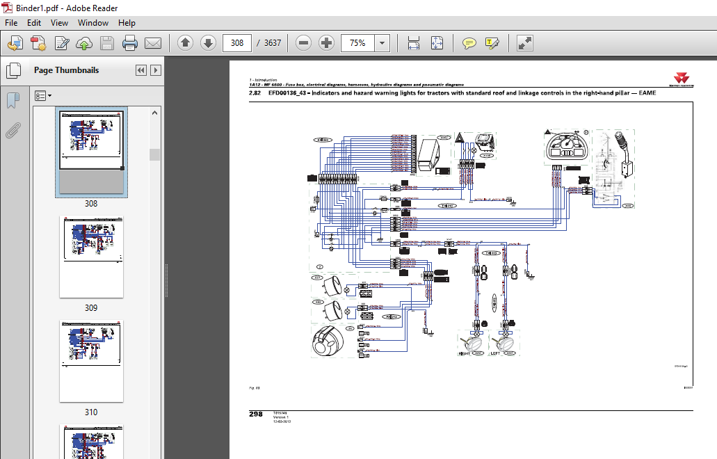
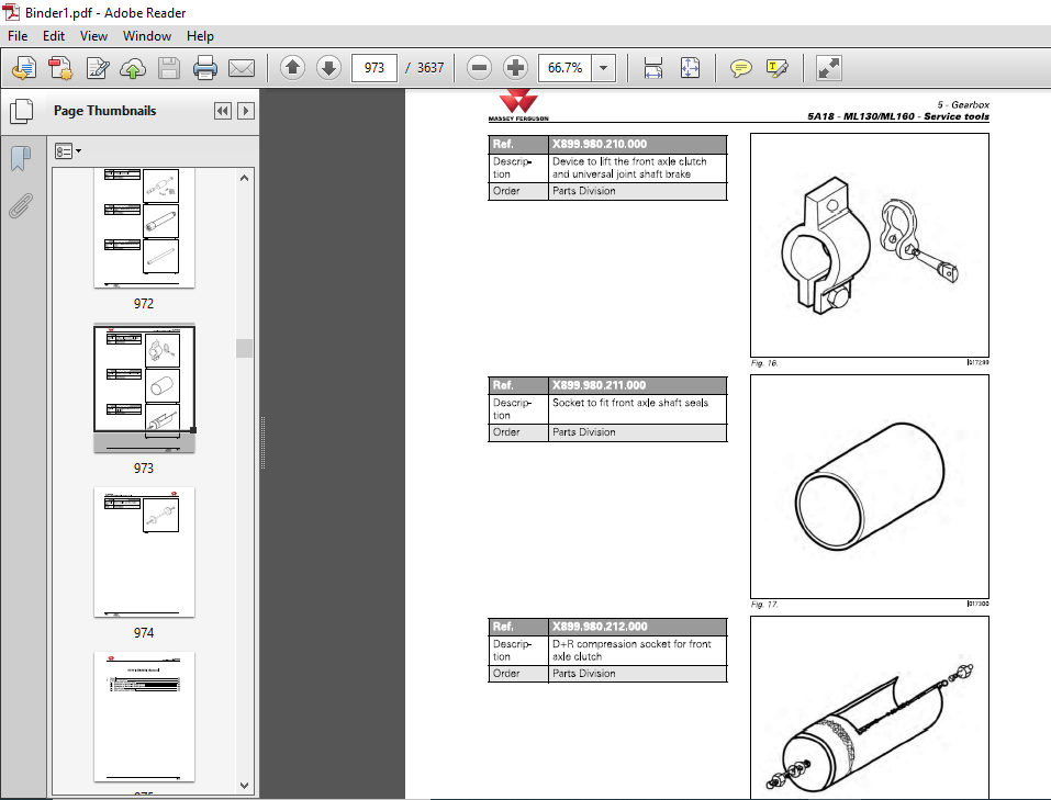
TABLE OF CONTENTS:
Massey Ferguson MF6600 Workshop Service Manual – PDF DOWNLOAD
Introduction
1A10 MF 6600 – General
MF 6600
1A11 MF 6600 – Error codes
1A12 MF 6600 – Fuse box, electrical diagrams, harnesses, hydraulics
diagrams and pneumatic diagrams
1A16 MF 6600 – Adjustments, bleeding and calibrations
2 Separation of assemblies
2A17 Front linkage – Removing and refitting
2B17 Front axle – Removing and refitting
2C17 Cooling unit – Removing and refitting
2D17 Front frame – Removing and refitting
2E17 Bonnet – Removing and refitting
2F17 Engine – Removing and refitting
2G17 Gearbox – Removing and refitting
2H17 Cab – Removing and refitting
2117 Pedal assembly – Removing and refitting
2J17 Rear axle – Removing and refitting
3 Engine
3A 11 Sisu Tier 4i engine – Error codes
3A12 Sisu Tier 4i engine – Electrical and hydraulics diagrams
3A 13 Sisu Tier 4i engine – Layout of components
3A14 Sisu Tier 4i engine – Tests and diagnostics
3A16 Sisu Tier 4i engine – Adjustments, bleeding and calibrations
3A 17 Sisu Tier 4i engine – Disassembly and reassembly
3B10 e3 SCR Technology engine – General
3B12 e3 SCR Technology engine – Electrical and hydraulic diagrams
3B13 e3 SCR Technology engine – Layout of components
3B17 e3 SCR Technology engine – Disassembly and reassembly
3B18 e3 SCR Technology engine – Service tools
4 Clutch
Chapter intentionally left blank
5 Gearbox
5A10 ML130/ML160 – General
5A11 ML130/ML160 – Error codes
5A12 ML 130/ML 160 – Electrical and hydraulics diagrams
5A13 ML 130/ML 160- Layout of components
5A14 ML 130/ML 160 – Tests and diagnostics
5A16 ML130/ML160 – Adjustments, bleeding and calibrations
5A17 ML 130/ML 160 – Disassembly and reassembly
5A18 ML 130/ML 160 – Service tools
5C10 GBA25 – General
5C11 GBA25 – Error codes
5C13 GBA25 – Layout of components
MF6600
Table of contents MASSEY FERGUSON
5C16 GBA25 – Adjustments, bleeding and calibrations
5C17 GBA25 – Disassembly and reassembly
5C20 GBA25/PowerShuttle – General
5C23 GBA25/PowerShuttle – Layout of components
5C27 GBA25/PowerShuttle – Disassembly and reassembly
5C28 GBA25/PowerShuttle – Service tools
5C30 GBA25/Powershift module – General
5C33 GBA25/Powershift module – Layout of components
5C37 GBA25/Powershift module – Disassembly and reassembly
5C38 GBA25/Powershift module – Service tools
5C40 GBA25/Robotic mechanical gearbox – General
5C43 GBA25/Robotic mechanical gearbox – Layout of components
5C47 GBA25/Robotic mechanical gearbox – Disassembly and reassembly
5C48 GBA25/Robotic mechanical gearbox – Service tools
5C50 GBA25/Creeper gears – General
5C53 GBA25/Creeper gears – Layout of components
5C57 GBA25/Creeper gears – Disassembly and reassembly
5C60 GBA25/Super creeper gears – General
5C63 GBA25/Super creeper gears – Layout of components
5C67 GBA25/Super creeper gears – Disassembly and reassembly
6 Rear axle
6A13 HA130/160/Final drives – Layout of components
6A17 HA130/160/Final drives – Disassembly and reassembly
6A21 HA 130/160/Differential – Error codes
6A22 HA 130/160/Differential – Electrical and hydraulics diagrams
6A23 HA 130/160/Differential – Layout of components
6A26 HA 130/160/Differential – Adjustments, bleeding and calibrations
6A27 HA 130/160/Differential – Disassembly and reassembly
6A31 HA 130/160/Tractor braking – Error codes
6A32 HA130/160/Tractor braking – Electrical and hydraulics diagrams
6A33 HA 130/160/Tractor braking – Layout of components
6A36 HA 130/160/Tractor braking – Adjustments, bleeding and calibrations
6A37 HA 130/160/Tractor braking – Disassembly and reassembly
6A51 HA 130/160/Hydraulic trailer braking – Error codes
6A52 HA130/160/Hydraulic trailer braking – Electrical and hydraulics
diagrams
HA 130/160/Pneumatic trailer braking – General
HA 130/160/Pneumatic trailer braking – Electrical and hydraulics
diagrams
HA 130/160/Pneumatic trailer braking – Layout of components
HA 130/160/Pneumatic trailer braking – Tests and diagnostics
HA 130/160/Pneumatic trailer braking – Adjustments, bleeding and
calibrations
HA 130/160/Pneumatic trailer braking – Disassembly and reassembly
GPA20 – General
GPA20 – Layout of components
GPA20/Trumpet housings – General
GPA20/Trumpet housings – Layout of components
GPA20/Trumpet housings – Disassembly and reassembly
GPA20/Trumpet housings – Service tools
GPA20/Differential – General
GPA20/Differential – Layout of components
MASSEY FERGUSON
MF6600
Table of contents
7
GPA20/Differential – Disassembly and reassembly
GPA20/Differential – Service tools
GPA20/Tractor braking – General
GPA20/Tractor braking – Layout of components
GPA20/Tractor braking – Adjustments, bleeding and calibrations
GPA20/Tractor braking – Disassembly and reassembly
GPA20/Tractor braking – Service tools
GPA20/Hydraulic trailer braking – General
GPA20/Hydraulic trailer braking – Layout of components
GPA20/Hydraulic trailer braking – Disassembly and reassembly
GPA20/Pneumatic trailer braking – General
GPA20/Pneumatic trailer braking – Electrical and hydraulics diagrams
GPA20/Pneumatic trailer braking – Layout of components
GPA20/Pneumatic trailer braking – Tests and diagnostics
GPA20/Pneumatic trailer braking – Adjustments, bleeding and
calibrations
GPA20/Pneumatic trailer braking – Disassembly and reassembly
GPA20/Pneumatic trailer braking – Service tools
GPA20/Hitch/Linkage – General
GPA20/Hitch/Linkage – Layout of components
GPA20/Hitch/Linkage – Adjustments, bleeding and calibrations
GPA20/Hitch/Linkage – Disassembly and reassembly
GPA20/Auto-hitch – General
GPA20/Auto-hitch – Adjustments, bleeding and calibrations
GPA20/Auto-hitch – Disassembly and reassembly
GPA20 +/Hitch/Increased capacity linkage – General
GPA20 +/Hitch/Increased capacity linkage – Layout of components
GPA20 +Hitch/Increased capacity linkage – Adjustments, bleeding
and calibrations
6D87 GPA20 +Hitch/Increased capacity linkage – Disassembly and
reassembly
6D88 GPA20 +Hitch/Increased capacity linkage – Service tools
Power take-off
7 A 11 HA 130/160/Power take-off – Error codes
7 A 12 HA 130/160/Power take-off – Electrical and hydraulics diagrams
7 A 13 HA 130/160/Power take-off – Layout of components
7 A 16 HA 130/160/Power take-off – Adjustments, bleeding and calibrations
7 A 17 HA 130/160/Power take-off – Disassembly and reassembly
7C10 GPA20 – General
7C20 GPA20/lntermediate shaft/Driving gear/PTO brake – General
7C23 GPA20/lntermediate shaft/Driving gear/PTO brake – Layout of
components
7C27 GPA20/lntermediate shaft/Driving gear/PTO brake – Disassembly and
reassembly
GPA20/GSPTO – General
GPA20/GSPTO – Layout of components
GPA20/GSPTO – Disassembly and reassembly
GPA20/Removable PTO shaft – General
GPA20/Removable PTO shaft – Layout of components
GPA20/Removable PTO shaft – Disassembly and reassembly
GPA20/Shiftable PTO shaft – General
GPA20/Shiftable PTO shaft – Layout of components
HA130/LS hydraulic system – Disassembly and reassembly
HA 130/LS hydraulic system – Service tools
HA130/LS hydraulic system/Hydraulic pumps – General
HA130/LS hydraulic system/Hydraulic pumps – Electrical and
hydraulics diagrams
HA130/LS hydraulic system/Hydraulic pumps – Layout of
components
HA130/LS hydraulic system/Hydraulic pumps – Tests and diagnostics
HA130/LS hydraulic system/Hydraulic pumps – Disassembly and
reassembly
HA130/LS hydraulic system/Hydraulic pumps – Service tools
HA130/LS hydraulic system/Auxiliary spool valves – General
HA130/LS hydraulic system/Auxiliary spool valves – Error codes
HA130/LS hydraulic system/Auxiliary spool valves – Electrical and
hydraulics diagrams
HA130/LS hydraulic system/Auxiliary spool valves – Layout of
components
HA130/LS hydraulic system/Auxiliary spool valves – Tests and
diagnostics
HA 130/LS hydraulic system/Auxiliary spool valves – Disassembly and
reassembly
HA130/LS hydraulic system/Auxiliary spool valves – Service tools
HA130/LS hydraulic system/Rear linkage – General
HA 130/LS hydraulic system/Rear linkage – Error codes
HA130/LS hydraulic system/Rear linkage – Electrical and hydraulics
diagrams
HA130/LS hydraulic system/Rear linkage – Layout of components
HA130/LS hydraulic system/Rear linkage – Tests and diagnostics
HA130/LS hydraulic system/Rear linkage – Disassembly and
reassembly
HA130/LS hydraulic system/Rear linkage – Service tools
HA130/LS hydraulic system/Front linkage – General
HA130/LS hydraulic system/Front linkage – Electrical and hydraulics
diagrams
HA130/LS hydraulic system/Front linkage – Layout of components
HA130/LS hydraulic system/Front linkage – Tests and diagnostics
HA130/LS hydraulic system/Front linkage – Adjustments, bleeding
and calibrations
HA130/LS hydraulic system/Front linkage – Disassembly and
reassembly
HA130/LS hydraulic system/Front linkage – Service tools
GPA20/Load Sensing – General
GPA20/Load Sensing – Electrical and hydraulics diagrams
GPA20/Load Sensing – Layout of components
GPA20/Load Sensing – Tests and diagnostics
GPA20/Load Sensing – Disassembly and reassembly
GPA20/Load Sensing/Right-hand cover plate – General
GPA20/Load Sensing/Right-hand cover plate – Layout of components
GPA20/Load Sensing/Right-hand cover plate – Disassembly and
reassembly
GPA20/Load Sensing/Right-hand cover plate – Service tools
GPA20/Load Sensing/Left-hand cover plate – General
GPA20/Load Sensing/Left-hand cover plate – Layout of components
9837 GPA20/Load Sensing/Left-hand cover plate – Disassembly and
reassembly
GPA20/Load Sensing/Linkage spool valve – General
GPA20/Load Sensing/Linkage spool valve – Layout of components
GPA20/Load Sensing/Linkage spool valve – Disassembly and
reassembly
GPA20/Load Sensing/Auxiliary spool valves – General
GPA20/Load Sensing/Auxiliary spool valves – Layout of components
GPA20/Load Sensing/Auxiliary spool valves – Adjustments, bleeding
and calibrations
9857 GPA20/Load Sensing/Auxiliary spool valves – Disassembly and
reassembly
Open Centre – General
Open Centre – Electrical and hydraulics diagrams
Open Centre – Tests and diagnostics
Open Centre/Right-hand cover plate – General
Open Centre/Right-hand cover plate – Layout of components
Open Centre/Right-hand cover plate – Disassembly and reassembly
Open Centre/Left-hand cover plate – General
Open Centre/Left-hand cover plate – Layout of components
Open Centre/Left-hand cover plate – Disassembly and reassembly
100 I/min Open Centre – General
100 I/min Open Centre – Electrical and hydraulics diagrams
100 I/min Open Centre – Tests and diagnostics
100 I/min Open Centre/Right-hand cover plate – General
100 I/min Open Centre/Right-hand cover plate – Layout of
components
9D27 100 I/min Open Centre/Right-hand cover plate – Disassembly and
reassembly
100 I/min Open Centre/Left-hand cover plate – General
100 I/min Open Centre/Left-hand cover plate – Layout of components
100 I/min Open Centre/Left-hand cover plate – Disassembly and
reassembly
Open Centre/Linkage spool valve – General
Open Centre/Linkage spool valve – Layout of components
Open Centre/Linkage spool valve – Disassembly and reassembly
Open Centre/Auxiliary spool valves – General
Open Centre/Auxiliary spool valves – Layout of components
Open Centre/Auxiliary spool valves – Adjustments, bleeding and
calibrations
Open Centre/Auxiliary spool valves – Disassembly and reassembly
Open CentreNalve 21 bar (305 psi) – General
Open CentreNalve 21 bar (305 psi) – Layout of components
Open CentreNalve 21 bar (305 psi) – Adjustments, bleeding and
calibrations
9E37 Open CentreNalve 21 bar (305 psi) – Disassembly and reassembly
Electricity
10A12 Lighting and equipment – Electrical and hydraulics diagrams
10810 Fuse box – General
10812 Fuse box – Electrical and hydraulics diagrams
10C14 Alternator – Tests and diagnostics
1OC17 Alternator – Disassembly and reassembly
MASSEY FERGUSON
MF6600
Table of contents
1OC18 Alternator – Service tools
10D10 Starter – General
10D14 Starter – Tests and diagnostics
10D17 Starter – Disassembly and reassembly
10E17 Triflash triangle – Assembly
11 Electronics
11A10 MF 6600 – List of all components
12 Cab
12A10 Standard air conditioning – General
12A 12 Standard air conditioning – Electrical and hydraulics diagrams
12A13 Standard air conditioning – Layout of components
12A14 Standard air conditioning – Tests and diagnostics
12A 16 Standard air conditioning – Adjustments, bleeding and calibrations
12A17 Standard air conditioning – Disassembly and reassembly
12810 Self-regulating air conditioning – General
12811 Self-regulating air conditioning – Error codes
12812 Self-regulating air conditioning – Electrical and hydraulics diagrams
12813 Self-regulating air conditioning – Layout of components
12814 Self-regulating air conditioning – Tests and diagnostics
12816 Self-regulating air conditioning – Adjustments, bleeding and
calibrations
12817 Self-regulating air conditioning – Disassembly and reassembly
12C10 Semi-active hydraulic suspension – General
12C12 Semi-active hydraulic suspension – Electrical and hydraulics
diagrams
12C13 Semi-active hydraulic suspension – Layout of components
12C16 Semi-active hydraulic suspension – Adjustments, bleeding and
calibrations
12C17 Semi-active hydraulic suspension – Disassembly and reassembly
13 Accessories
accessories kits
14 Service tools
14A01 General
14A02 Separation of assemblies
14A03 Engine
14A05 Gearbox
14A06 Rear axle
14A07 Power take-off
14A08 Front axle
14A09 Hydraulics
14A 10 Electricity
14A11 Electronics
14A12 Cab
PLEASE NOTE:
- This is the SAME exact manual used by your dealers to fix your vehicle.
- The same can be yours in the next 2-3 mins as you will be directed to the download page immediately after paying for the manual.
- Any queries / doubts regarding your purchase, please feel free to contact [email protected]
S.V


