Massey Ferguson MF 7200 CEREA 7274 CEREA 7278 Operators Manual PDF
$28.95
Massey Ferguson MF 7200 CEREA 7274 CEREA 7278( Auto Level Rotatory Separator)Operators Manual – PDF DOWNLOAD
Description
Massey Ferguson MF 7200 CEREA 7274 CEREA 7278( Auto Level Rotatory Separator)Operators Manual – PDF DOWNLOAD
FILE DETAILS:
Massey Ferguson MF 7200 CEREA 7274 CEREA 7278( Auto Level Rotatory Separator)Operators Manual – PDF DOWNLOAD
Language : English
Pages : 374
Downloadable : Yes
File Type : PDF
IMAGES PREVIEW OF THE MANUAL:
TABLE OF CONTENTS:
Massey Ferguson MF 7200 CEREA 7274 CEREA 7278( Auto Level Rotatory Separator)Operators Manual – PDF DOWNLOAD
General Information 9
1 1 Appropriate Use 11
1 2 Preface 12
1 3 Product Identification 13
1 4 Sectional Drawing and Parts Identification 14
2 Safety 17
2 1 General Safety Precautions 18
2 2 Attention – Warning Symbols 19
2 3 Safety Precautions 20
2 4 Road Transport 22
2 5 CE Marking and Type Plate on the Combine 23
2 6 Warning/Instruction decals 34
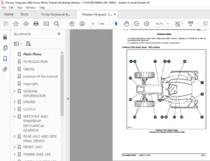
2 7 Position of CE Markings and Type Plate 38
3 Operation, Controls and Cab 41
3 1 Before Start 43
3 2 Operator Cab, Arrangement and Controls 46
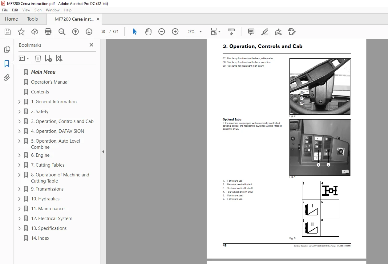
Optional Extra 48
3 3 Safety Precautions 49
3 4 Starting and Stopping the Engine 50
Starting the engine 50
Stopping the engine 51
3 5 Drive Controls 52
Multi-Function Lever 52
Adjustable Armrest, 53
Changing Gears, 53
Reduced Engine Revolutions in Road Transport (Speed Matching System) 54
Steering column 55
Brakes, 55
Adjustment of Operator Seat 56
Adjustment of Air-Suspended Seat 56
Ladder 57
Removable Ladder 57
Lights 58
Main Light and Work Light, 58
3 6 Operator Cab, Ventilation, 59
Air-Conditioning 59
Using the Air-Conditioning 59
3 7 Printer 60
Exchanging Paper and Ribbon in Printer 60
Inserting the Paper Roll, 60
Fitting the Ribbon, 60
3 8 Four-Wheel Drive 61
Activating Four-Wheel Drive, 61
Forward Speed 61
Operation of Four-Wheel Drive 62
Service 62
3 9 Other Optional Extra 63
Reversing Camera 63
Electrically Adjustable Rearview Mirrors, 63
4 Operation, DATAVISION 65
4 1 Safety Precautions 67
4 2 DATAVISION 69
Menu Structure and Operation 69
Operating DATAVISION on Terminal 70
Contents
2 Combine Operator’s Manual MF 7274-7278 CEREA Range – EN_D63110100M9
Operating the Terminal by Remote Control in the Multi-Function Lever 71
Contrast and Brightness Control 72
Cleaning the Terminal 72
Data Cards 73
DATAVISION Menu Structure 73
4 3 Harvest Menu 75
4 4 Main Menu 79
4 5 Monitoring 81
Shaft Speeds 81
Engine Monitoring/Alarm 81
Engine Safety Alarm 82
Information 82
Shaft Speeds 83
4 6 Harvesting Data 85
Accumulated Machine Data, 85
Trip Data and Field Data, 85
4 6 1 Data Logging in General, 86
4 6 2 Using Data Logging 88
Creating a New Field Job 88
Starting a Job 90
Field Map for a Job 92
Data Logging Messages 94
4 6 3 Data Logging Setup 96
Marker Setup 97
Selecting Position Data 98
Setup of Logging Rate 98
4 6 4 Using Markers 99
4 7 Operator Manual 101
Harvest Settings 101
Routine Servicing 101
DATAVISION 101
4 8 Diagnostics 103
Electric Diagnostics, 103
Yield Meter 103
System Information, 103
System Setup 103
Programming Computer, 103
Control, 103
GPS Information, 104
DGPS Information, 105
Programming 107
Diagnosis 107
Screen Calibration (Touch Calibration) 107
4 9 Coding, 109
Clock Adjustment, 109
Language, 109
Area Measuring 110
Table Calibration 111
Returns Volume 111
Grain loss monitor 111
Concave Calibration 112
Constant Flow 112
Wheel Track and Auto Level Combine 112
Coding of Electrical Straw Deflectors 113
Straw chopper vibrations 113
Lead Time and Lag Time 114
Calibration of Actuator for Electrical Sieves 115
4 10 Settings 117
Harvest Settings, 117
Table Settings 120
Contents
Combine Operator’s Manual MF 7274-7278 CEREA Range – EN_D63110100M9 3
Machine Settings, 122
4 11 Returns Volume Monitor 124
Coding, 124
4 12 Grain Loss Monitoring 125
Sensors 125
Adjustment of Grain Loss Sensors, 125
4 13 Shaft Alarm Calibration 126
4 14 Straw Chopper Vibrations 127
Coding 127
4 15 Yield Meter 128
4 15 1 Yield meter (Isotopic) 128
Measuring Principle 128
Mass Flow Measuring 128
Yield Meter Status 129
Using the Yield Meter 129
Calibration of Yield Meter 129
4 15 2 Micro-Trak Yield Meter 130
Measuring Principle 130
Zero Point for Micro-Trak Yield Meter 130
Calibration of Micro-Trak Yield Meter 130
Slope Compensation for Micro-Trak Yield Meter 130
4 15 3 Yield Meter Calibration 131
4 16 Moisture Meter 133
Continuous Moisture Measuring 133
Measuring Principle 133
Using the Moisture Meter 133
Cleaning the Moisture Meter 134
Calibration of Moisture Meter 135
4 17 Cutting Height Control 137
Cutting Height Control Setting and Operation 137
Coding of Table 138
4 18 Field Pressure Control 139
Field Pressure Control Setting and Operation 139
4 19 Auto Level Table 141
Bleeding 141
Coding of Auto Level Table 142
Calibration of Table Angle 142
4 20 Operation of Auto Level Table 143
Manual Control 143
Levelling at Turns 143
4 21 Interaction Between Table Controls 144
4 22 Checking and Adjusting the Ground Sensors 145
4 23 Constant Flow 146
Start-up and Adjustment of Constant Flow 146
Constant Flow Engagement 148
5 Operation, Auto Level Combine 151
5 1 Safety Precautions 153
Safety System 154
5 2 Combinations 155
Selecting Combination 155
5 3 Auto Level Combine 156
Manual Control of Auto Level Combine 156
5 4 Auto Level Combine/Table 157
Combine 157
Transport, 157
Auto Level table 158
5 5 Calibration of Auto Level Combine 159
Contents
4 Combine Operator’s Manual MF 7274-7278 CEREA Range – EN_D63110100M9
Errors during Calibration 160
5 6 Coding of Auto Level Table 160
Zero Cutting Height 160
5 7 Attachment/Removal of Table 161
5 8 Operation of Auto Level Combine/Auto Level Table 162
Combinations 162
Priority of Hydraulic Functions 163
5 9 Safety System, Auto Level 164
Automatic Control of the Tilt Sensor Function 164
Safety System 164
Hose Breach Protection for Auto Level Hydraulics 165
5 10 Troubleshooting 166
Mechanical Connections 166
Checking Sensor Adjustment and Inclinometer 166
Machine Not Levelling Correctly 167
5 11 Servicing and User Tips 168
Retrofit of New DATAVISION Auto Level Job Computer and Sensors 168
Unintentional Use of Manual Keys in Automatic Mode 168
Diagnostics – Auto Level Combine Functions and Sensors 168
6 Engine 169
6 1 Safety Precautions 171
6 2 Engine Types 172
6 3 Air-Intake 172
Filter System 172
6 4 Cooling System 173
Rotary Screen and Dust Aspirator 173
Coolers 173
Coolant 174
Checking the Fan Belt Tension 174
6 5 Fuel System 175
Filter change 176
6 6 Engine Oil/Change 177
Oil and Filter Change 177
6 7 Cleaning the Engine Compartment 177
6 8 Electronic Engine Management 178
6 9 Engine Trouble Shooting 178
EEM3 Electronic Engine Management – Failure Codes (Self-Diagnosis) 178
7 Cutting Tables 181
7 1 Safety Precautions 183
7 2 Attachment of Table, Standard and Auto Level 184
Mounting 184
Alignment of Table 185
7 3 Removal of Table 186
Table Trailer 186
Attachment of Combine and Trailer 187
Supports 187
7 4 Reel 188
Reel Adjustment Up/Down, Fore/Aft 188
Bleeding 188
Reel Rotation 189
Reel Tine Bars 189
Adjustment of Reel in the Table 189
7 5 Knife 190
Knife and Knife Drive 190
Adjustment of Knife Up/Down 190
Contents
Combine Operator’s Manual MF 7274-7278 CEREA Range – EN_D63110100M9 5
Checking the Knife Clearance 190
Fingers 190
7 6 Main Crop Elevator 191
Table Auger 191
Cut-Off Strip 191
Replacement of Feathering Fingers 191
Auger Flight Extensions, 20-22-25′ Tables 191
Reversing 192
7 7 Transmission 193
PowerFlow Table, Knife Drive and Table Auger 193
Slip Clutch for Table Auger 193
7 8 PowerFlow Table 194
Inspection and Start-Up of PowerFlow Belts 194
Adjustment of Belts 194
Front Scrapers 195
Rear Scrapers and Adjustment of Bearing Housings 195
Table Bottom 195
Cleaning 196
7 9 Crop Lifters 196
Using Crop Lifters 196
7 10 Vertical Knives and Straw Dividers 197
Vertical Knife 197
Mounting of Vertical Knife 197
Torpedo Divider and Straw Divider Bow 198
Mounting of Straw Dividers 198
Adjustment of Torpedo Divider 198
7 11 Fixed Table Auger Fingers 199
Using Fixed Table Auger Fingers 199
High Table Sides 199
7 12 Main crop elevator 200
Crop Elevator Chain 200
Transmission for Table 200
Stone Trap 200
Initial Adjustment of Cutting Height Indication 201
8 Operation of Machine and Cutting Table 203
8 1 Safety Precautions 205
8 2 Operation of Table 206
Table Height and Table Automatic Control 206
Cutting Height Control 207
Field Pressure Control 207
Preset Cutting Height 208
Auto Level Table 208
Table Engagement – Emergency Stop 209
Slip Clutch 209
8 3 Threshing Unit Transmission 210
Threshing Unit Engagement 210
Cylinder Variator 210
Turning Tool for Cylinder 211
8 4 Concave Setting, Electrically Adjustable 212
Operation of Concave 212
Concave Setting 212
8 5 Threshing 214
Concave Filler Plates 214
Straw Walkers 214
Rear Beater Curtain 215
8 6 Straw Chopper and Spreader Hood 216
Straw chopper 216
Adjustment of Spreader Hood 217
Contents
6 Combine Operator’s Manual MF 7274-7278 CEREA Range – EN_D63110100M9
Counter Knives and Cross Bar 218
Replacement of Knives 219
8 7 Fanning Mill and Sieves 220
Fanning Mill 220
Shaker Shoe 220
Shaker Shoe with Electrical Sieves 221
Manual Adjustment of Sieves 221
Cleaning of Sieves and Main Grain Pan 222
Cleaning the Sieves 222
Shaker Shoe Light 223
Special Sieves 224
8 8 Internal Grain Transport 225
Auger Housing/Elevators 225
Returns Thresher 225
Tank Filling Auger 226
Grain Tank 227
Unloading Auger 228
Unloading Auger Clutch 228
Unloading Tube 229
8 9 Rotary Separator 230
Change of Rotor Revolutions 230
Concave Setting 230
8 10 Straw hood 231
Alarm switch for straw hood blocked 231
Blockage in straw hood 231
8 11 Chaff Spreader 232
Setting 232
8 12 Maize Threshing 233
Attachment of Maize Header 233
Area measuring 233
Main crop elevator 234
Concave/Cylinder/Stone Trap 234
Concave/Initial Settings 234
Threshing cylinder 234
Rotary separator 235
Shaker Shoe 235
Machine with Electrical Sieves 235
Straw walkers 235
Bottom Auger Cover Plate 236
Scrapers 236
Rear Beater Curtain 236
Straw chopper 236
8 13 Suggested Harvest Settings 237
8 14 Threshing 238
9 Transmissions 239
9 1 Safety Precautions 241
9 2 Adjustment of Transmissions 242
General 242
Threshing Unit Clutch 242
Hydrostatic Transmission 242
9 3 Transmissions 243
Rear Beater 243
Main Crop Elevator and Table 243
Straw chopper 243
Threshing cylinder 244
Unloading Auger 244
Shaker Shoe and Chaff Spreader Counter Drive, and Straw Walker Drive 245
Filling and Returns System Countershaft, 246
Contents
Combine Operator’s Manual MF 7274-7278 CEREA Range – EN_D63110100M9 7
Returns Elevator and Returns Thresher 246
Tank Filling Elevator and Tank Filling Auger 247
Dust aspirator 247
Rotary screen 248
Fanning Mill 249
Rotary Separator 249
Alternator and Fan, 249
Air-conditioning 250
9 4 Transmission Diagram, Left-Hand Side 252
9 5 Transmission Diagram, Right-Hand Side 254
10 Hydraulics 257
10 1 Safety Precautions 259
10 2 Hydraulic System, Standard Combine 260
Hydrostatic Transmission 260
10 3 Hydraulic System, Four-Wheel Drive 261
Hydrostatic Transmission 261
10 4 Oil Change 262
Draining Oil 262
Refilling Oil 262
10 5 Filter Change 263
Return Oil Filter 263
Storage of Hydraulic System 263
10 6 Auxiliary Hydraulics 264
Functions and Auxiliary Hydraulics 264
Reel Adjustment Fore/Aft – Up/down 264
10 7 Hydraulics Diagram, Standard Combine 266
10 8 Hydraulics Diagram, Auto Level Combine 268
10 9 Hydraulics Diagram for Chaff Spreader 270
11 Maintenance 271
11 1 Safety Precautions 273
11 2 Undercarriage 275
Wheel Nut Torques 275
11 3 Tyre Pressure 276
11 4 Lubrication Points 278
Daily/10 Hours (Red) 278
50 hours (blue) 278
100 hours (yellow) 278
200 hours (white) 279
11 4 1 Lubrication Chart 280
11 4 2 Lubrication Points, Auto Level Combine 282
11 5 Lubricants and Operating Fluids 283
11 6 Maintenance Required 284
11 7 Gear Oil Change 286
Gearbox 286
Final Drives 286
Wobble Box for Knife Drive 286
11 8 Air-Conditioning 287
Diagram for air-conditioning 287
Maintenance 287
11 9 Cleaning and Off-Season Storage 288
Cleaning 288
Off-season storage 289
Storage of Engine, Fuel System and Hydraulic System 290
Periodical Start-Up 290
Removal of Main Crop Elevator 291
Contents
8 Combine Operator’s Manual MF 7274-7278 CEREA Range – EN_D63110100M9
Removal of Elevator Chains 291
After Off-Season Storage 291
11 10 Adjustment of Brakes 292
Adjustment of Foot Brakes, Disc Brakes 292
Adjustment of Parking Brake, Drum Brake 292
11 11 Dealer Servicing Schedule for CEREA Combine Range 293
12 Electrical System 299
12 1 Safety Precautions 301
12 2 Electrical System 302
Charging System 302
Electric Boxes and Main Switch 302
12 3 External 12V connectors 303
12 4 Electro-Hydraulic System 305
Hydraulic safety 305
12 5 Key to Signatures for Wiring Harness 306
Wire Codes 306
Component Codes 306
12 6 Position of Connectors in Electric Box 307
12 7 Fuses and Relays, Electric Box and Cab 308
12 8 Key to Symbols 310
12 9 Fuses, Alphabetical 311
12 10 Fuse Ratings 312
12 11 W-Connecting Points 313
12 12 Diagrams survey 314
12 13 Diagrams 317
13 Specifications 363
13 1 Dimensions and Specifications 363
14 Index 367
DESCRIPTION:
Massey Ferguson MF 7200 CEREA 7274 CEREA 7278( Auto Level Rotatory Separator)Operators Manual – PDF DOWNLOAD
General Information:
- Operator’s Manual MF 7274-7278 CEREA Range – EN_D63110100M9 1.2 Preface This Manual The purpose of this manual is to enable the owner/operator to handle and maintain the combine efficiently. Time spent in becoming familiar with the Operator’s Manual now will save time in the field.
- Wide variations in operation conditions make it impossible for the Company to make comprehensive or definite statements in its publications concerning performance and the use of its machines, or to accept liability for any damage which may result from errors or omissions.
- The specifications and illustrations contained in this manual pertain to combines manufactured for specific countries.
- Due to differing laws and requirements in various countries, some apparent discrepancies may result between any particular combine and those depicted in this manual. Some accessories and optional equipment appearing in this manual are not necessarily available in all territories. AGCO service During the warranty period, all maintenance and repair work must be carried out by the AGCO dealer who will carefully carry out detailed checks of the progress and performance of the new combine.
- To obtain best results from an AGCO combine, it is important to continue regular servicing and periodical inspection after the warranty has expired. All major overhaul work on the combine must be carried out by a local AGCO dealer; an experienced technician will detect any problems which may arise between two overhauls.
- Mechanical staff regularly follow training courses to update their knowledge of the product, maintenance and repair techniques and the use of special modern tools and equipment for troubleshooting.
- They receive regular Service Bulletins and have access to all the workshop manuals and technical publications required to carry out repairs or maintenance meeting the quality standards required by AGCO. Warning concerning spare parts Parts other than original AGCO parts are likely to be of lower quality.
- AGCO disclaims all liability in the event of loss or damage arising as a result of such parts being fitted. The manufacturer’s warranty may also become void, if such parts are fitted during the normal warranty period.
G.B 09/04/25