

Mack E7 E-TECH Engine Inc Left Side Redesign Shop Manual
FILE DETAILS:
Mack E7 E-TECH Engine Inc Left Side Redesign Shop Manual – PDF DOWNLOAD
LANGUAGE:ENGLISH
PAGES:365
DOWNLOADABLE:YES
FILE TYPE:PDF
VIDEO PREVIEW OF THE MANUAL:

IMAGES PREVIEW OF THE MANUAL:
DESCRIPTION:
Mack E7 E-TECH Engine Inc Left Side Redesign Shop Manual
Service Procedures and Tool:
Usage Anyone using a service procedure or tool not recommended in this manual must first satisfy himself thoroughly that neither his safety nor vehicle safety will be jeopardized by the service method he selects. Individuals deviating in any manner from the instructions provided assume all risks of consequential personal injury or damage to equipment involved. Also note that particular service procedures may require the use of a special tool(s) designed for a specific purpose. These special tools must be used in the manner described, whenever specified in the instructions.
Mack Trucks, Inc. cannot anticipate every possible occurrence that may involve a potential hazard. Accidents can be avoided by recognizing potentially hazardous situations and taking necessary precautions. Performing service procedures correctly is critical to technician safety and safe, reliable vehicle operation. The following list of general shop safety practices can help technicians avoid potentially hazardous situations and reduce the risk of personal injury. DO NOT perform any services, maintenance procedures or lubrications until this manual has been read and understood.
- Perform all service work on a flat, level surface. Block wheels to prevent vehicle from rolling.
- DO NOT wear loose-fitting or torn clothing. Remove any jewelry before servicing vehicle.
- ALWAYS wear safety glasses and protective shoes. Avoid injury by being aware of sharp corners and jagged edges.
TABLE OF CONTENTS:
Mack E7 E-TECH Engine Inc Left Side Redesign Shop Manual
INTRODUCTION 1
SAFETY INFORMATION 2
Advisory Labels 2
Service Procedures and Tool Usage 3
EXPLANATION OF NUMERICAL CODE 5
ABOUT THIS MANUAL 6
Changes from the Existing E-Tech™ Service Procedures Manual 6
ABOUT THE E-TECH™ ENGINE AND ITS SERVICE 7
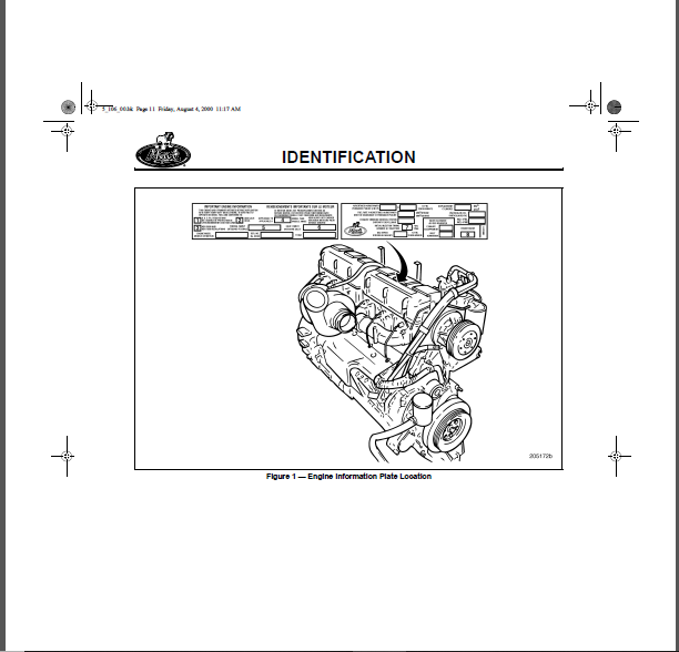
IDENTIFICATION 9
ENGINE MODEL IDENTIFICATION 10
Engine Information Plate 10
Engine Serial Number Identification 12
DESCRIPTION & OPERATION 13
E-TECH™ ENGINE DESIGN FEATURES 14
Electronic Unit Pumps 14
V-MAC III 16
Belt Drive System 24
J-Tech™ Engine Brake 24
Camshaft 27
Valve Train 27
Low-Pressure Fuel System 32
Fuel Filtration System 34
High-Pressure Fuel System 35
High-Pressure Fuel Injection Lines 36
Fuel Injector Assemblies 36
Cylinder Block 37
Crankshaft 40
Block Heater for Front (Water Pump) Location 40
Cylinder Head 41
Cylinder Head Gasket 43
Gear Train 44
Air Compressor 45
Power Steering Pump 45
Vibration Damper Hub 45
Front Cover 46
Centri-Max® Oil Filter Breather Vent 47
Lubrication System 47
GLOSSARY OF TERMS 55
TROUBLESHOOTING 57
ENGINE SYMPTOM DIAGNOSIS 58
V-MAC III Diagnostics 58
CAMSHAFT TIMING AND LOBE LIFT CHECKS 66
Camshaft Timing Check 66
Camshaft Lobe Lift Check 66
CHASSIS-MOUNTED CHARGE AIR COOLING TESTS 67
General Information 67
Special Tool Required 67
CMCAC Troubleshooting 67
CMCAC Pressure Test 68
Restriction Pressure Test 69
frontfm Page iv Friday, August 4, 2000 11:16 AM
Core Inspection 70
CMCAC Preventive Maintenance 70
CYLINDER HEAD AND CYLINDER BLOCK LEAK TEST PROCEDURE 71
Cylinder Head and Head Gasket Check — In Chassis 71
Cylinder Head Fuel Passages Leak Check — In Chassis 72
Cylinder Block/Cylinder Head Coolant Passages Leak Check — In Chassis 72
Cylinder Head Oil Passage Leak Check — Out of Chassis 74
Cylinder Head Coolant Passage Leak Check — Out of Chassis 75
Cylinder Block Coolant Passage Leak Check — Out of Chassis 76
ENGINE BRAKE TESTS 78
Operational Tests 78
Electrical Troubleshooting 79
Hydraulic/Mechanical Troubleshooting 80
Final Test 82
Troubleshooting Guide 83
MAINTENANCE 87
BELT DRIVE SYSTEM TENSIONING 88
Manually Tensioned System 88
Automatically Tensioned System 88
FILTER ELEMENT REPLACEMENT 89
General Information 89
Crankcase Breather Filter Cleaning 90
Oil Filter Element Replacement 90
Fuel Filter Replacement 93
Coolant Conditioner Replacement 94
REPAIR INSTRUCTIONS 95
ENGINE REMOVAL 96
General Instructions 96
Removal from Vehicle 96
ENGINE DISASSEMBLY 99
General Instructions99
Filter Element Removal 99
Oil Cooler and Oil Filter Mounting Bracket Assembly Removal101
Mounting Engine in Stand 103
Alternator Removal 105
Engine Electronic Control Unit (EECU) Removal 105
Fuel Filter Adapter Assembly Removal 107
Coolant Conditioner Element Removal 108
Oil Cooler-to-Water Pump Inlet Line Removal 109
Thermostat Removal 110
Coolant Manifold Removal 111
Air Inlet Manifold Removal 112
Water Pump Removal 112
Turbocharger Removal 113
Fuel Nozzle Inlet Tube Assembly Removal 113
Exhaust Manifold Removal 114
Engine Wiring Harness Removal 115
Engine Electronic Control Unit (EECU) and Cooling Plate Removal 115
Electronic Unit Pump (EUP) Removal 116
Oil Fill Tube Removal 116
frontfm Page v Friday, August 4, 2000 11:16 AM
vi
TABLE OF CONTENTS
Air Compressor Removal 117
Valve Cover and Spacer Removal 118
Rocker Arm, Valve Yoke and Push Rod Removal 119
Nozzle Holder Removal 121
Cylinder Head Assembly Removal 122
Vibration Damper and Crankshaft Hub Removal 123
Oil Pan Removal 123
Oil Pump Removal 125
Front Cover Removal 126
Auxiliary Shaft Removal 127
Camshaft Removal 128
Piston and Connecting Rod Assembly Removal 129
Flywheel Removal131
Flywheel Housing Removal 132
Main Bearing Cap Removal 133
Crankshaft Removal 134
CYLINDER BLOCK RECONDITIONING 134
Special Tools Required 134
Piston Cooling Spray Nozzle Removal 134
Cylinder Sleeve Removal 135
Cleaning and Inspection 136
Cylinder Sleeve Counterbore 137
Cup Plug Replacement 142
Pipe Plug Replacement 143
H-Ring Replacement 143
Camshaft Bushing Replacement 145
Auxiliary Shaft Bushing Replacement 148
Cylinder Sleeve Installation 152
Piston Cooling Spray Nozzle Installation 157
Cylinder Block Dowel Pin Replacement 159
CRANKSHAFT AND FLYWHEEL BENCH PROCEDURES 161
General Information 161
Crankshaft Inspection 161
Crankshaft Dowel Pin Replacement 162
Crankshaft Gear Replacement 163
Crankshaft Wear Ring Installation 164
Flywheel Inspection and Resurfacing 167
AUXILIARY SHAFT AND CAMSHAFT BENCH PROCEDURES 168
Auxiliary Shaft Inspection 168
Camshaft Inspection 168
CONNECTING ROD AND PISTON BENCH PROCEDURES 173
Connecting Rod Inspection and Reconditioning 173
Piston Inspection and Cleaning 176
Piston Ring Replacement 177
Assembling Connecting Rod to Piston 180
CYLINDER HEAD OVERHAUL 181
Special Tools Required 181
Inlet and Exhaust Valve Removal 181
Cylinder Head Inspection185
Fire Ring Groove Cutting 185
Valve Guide Replacement 188
frontfm Page vi Friday, August 4, 2000 11:16 AM
TABLE OF CONTENTS
vii
Valve Seat Insert Replacement 191
Valve Spring Inspection 196
Injection Nozzle Holder Insert Replacement 197
Valve Yoke Guide Pin Replacement 198
Cylinder Head Cup Plug Replacement 199
Cylinder Head Pipe Plug Replacement 200
Valve Replacement 202
VALVE ROCKER ARM SHAFT BENCH PROCEDURES 206
Rocker Arms 206
Valve Rocker Arm Shaft Disassembly (without/with Engine Brake) 206
Inspection 206
Valve Rocker Arm Shaft Reassembly (without Engine Brake) 207
Valve Rocker Arm Shaft Reassembly (with J-Tech™ Engine Brake)209
LUBRICATION SYSTEM BENCH PROCEDURES 211
Oil Cooler Assembly Reconditioning 211
Oil Pump Reconditioning 211
COOLING SYSTEM COMPONENTS BENCH PROCEDURES 215
Oil Cooler Reconditioning 215
Water Pump Reconditioning 218
FUEL SYSTEM COMPONENTS BENCH PROCEDURES 219
Electronic Unit Pump (EUP) Inspection 219
Installation of Electronic Unit Pump Plunger Spring and Seat 219
Fuel Injector Nozzle Cleaning221
ENGINE REASSEMBLY 222
General Instructions 222
Crankshaft Installation 222
Main Bearing Cap Installation224
Piston and Connecting Rod Installation 230
Flywheel Housing Installation 234
Crankshaft Rear Oil Seal Installation238
Flywheel Installation 240
Valve Lifter Installation 242
Camshaft Installation 242
Camshaft Core Plug Installation243
Camshaft Idler Gear Installation244
Auxiliary Shaft Installation 245
Oil Pump Installation 246
Front Cover Installation247
Crankshaft Front Seal Installation 248
Crankshaft Hub Installation 249
Vibration Damper Installation 249
Oil Pan Installation 250
Cylinder Head Installation 252
Exhaust Manifold Installation 255
Nozzle Holder Assembly Installation 257
Push Rod Installation 259
Valve Yoke Installation 260
Rocker Arm and Engine Brake Installation 261
Valve Cover and Spacer Installation 264
Oil Fill Tube Installation 265
Engine ECU/Cooling Plate Installation 266
frontfm Page vii Friday, August 4, 2000 11:16 AM
viii
TABLE OF CONTENTS
Air Compressor Installation 267
Electronic Unit Pump Installation 268
Engine Wiring Harness Installation 269
Fuel Nozzle Inlet Tube Assembly Installation 269
Turbocharger Installation270
Water Pump Installation271
Oil Cooler and Oil Filter Mounting Bracket Installation 272
Coolant Manifold Installation 274
Air Inlet Manifold Installation 276
Thermostat, Housing and Seal Installation276
Coolant Conditioner Installation278
Fuel Filter Adapter Assembly Installation 278
Engine ECU Installation280
Oil Cooler-to-Water Pump Inlet Line Installation 280
Alternator Installation 281
Removing Engine from Engine Stand281
Plate-Type Oil Cooler and Oil Filter Mounting Bracket Assembly Installation282
ENGINE INSTALLATION 284
General Instructions 284
Engine Installation into Vehicle284
IN-CHASSIS PART/COMPONENT PROCEDURES 286
Electronic Unit Pump (EUP) Replacement286
Camshaft Replacement (Engine in Chassis)288
Engine Brake Control Valve Replacement 293
Valve Lifter H-Ring Installation Check295
ENGINE SETUP AND ADJUSTMENTS297
Fuel Injection Timing 297
Valve Yoke, Valve Lash and Engine Brake Adjustments297
Engine Speed and Position Sensors Installation and Adjustment 304
Electronic Unit Pump (EUP) Calibration 305
ENGINE FINAL PREPARATION AND OPERATIONAL CHECK 306
Filter Element Installation306
Engine Lubrication System 306
Turbocharger 306
Cooling System 307
Fuel System307
Engine Operational Check 307
REBUILT ENGINE RUN-IN PROCEDURES 308
General Instructions 308
Run-In Check 308
SPECIFICATIONS 309
E-TECH™ ENGINE MECHANICAL SPECIFICATIONS 310
Performance Specifications 310
Material and Dimensional Data 311
E-Tech™ Component Torque Specifications 319
SPECIFICATION FOOTNOTES 328
E-TECH™ ENGINE LUBRICANT AND SEALANT SPECIFICATIONS 329
FASTENER TORQUE 330
Fastener Selection and Installation 330
Fastener Sizes and Types 331
frontfm Page viii Friday, August 4, 2000 11:16 AM
TABLE OF CONTENTS
ix
SCHEMATICS & DIAGRAMS 333
ENGINE SYSTEM SCHEMATICS (FLUIDS FLOW) 334
Cooling System Flow Diagram 334
Lubrication System Flow Diagram 335
Fuel System Flow Diagram 336
SPECIAL TOOLS & EQUIPMENT 337
E-TECH™ ENGINE SPECIAL TOOLS 338
Special Tools for Engine Overhaul 338
V-MAC III Special Tools341
INDEX 343
PLEASE NOTE:
- This is not a physical manual but a digital manual – meaning no physical copy will be couriered to you. The manual can be yours in the next 2 mins as once you make the payment, you will be directed to the download page IMMEDIATELY.
- This is the same manual used by the dealers inorder to diagnose your vehicle of its faults.
- Require some other service manual or have any queries: please WRITE to us at [email protected]


Bode William –
Excellent service