

Linkbelt 225 SPIN ACE TIER III EXCAVATORS SHOP MANUAL RST-15-00-001LX – PDF DOWNLOAD
FILE DETAILS:
Linkbelt 225 SPIN ACE TIER III EXCAVATORS SHOP MANUAL RST-15-00-001LX – PDF DOWNLOAD
Language : English
Pages : 782
Downloadable : Yes
File Type : PDF
Size: 102 MB
IMAGES PREVIEW OF THE MANUAL:


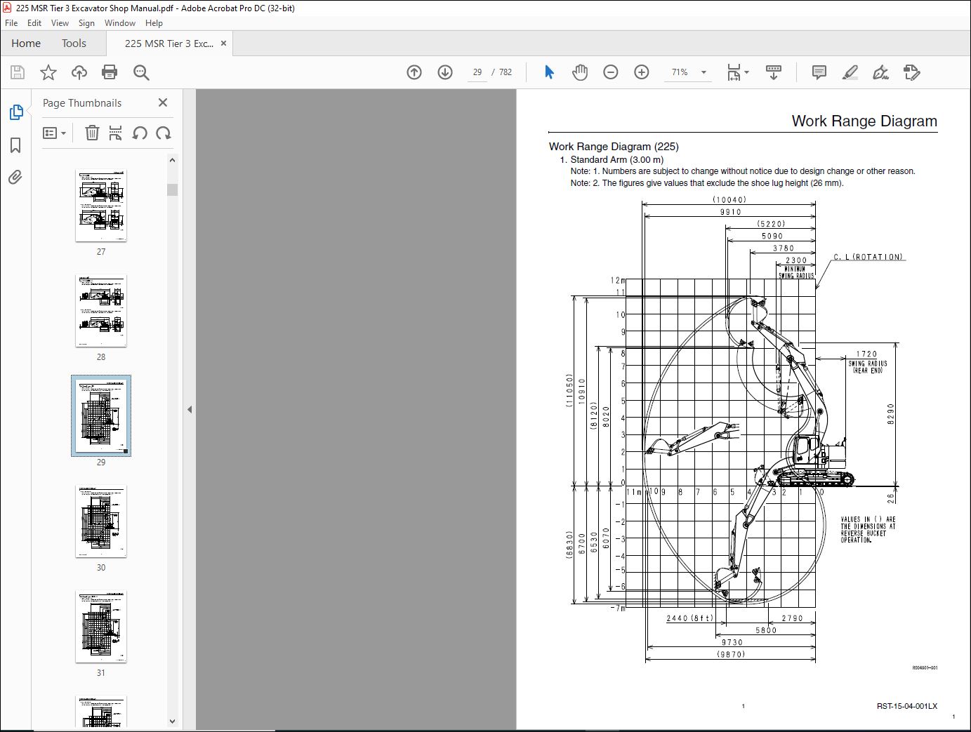
TABLE OF CONTENTS:
Linkbelt 225 SPIN ACE TIER III EXCAVATORS SHOP MANUAL RST-15-00-001LX – PDF DOWNLOAD
Main body
Specifications
Overall
1. Main Data
2. Performance
3. Main Body Dimensions
4. Engine
5. Cooling System
6. Upper Side Work System
7. Operating Device
8. Swing Units
9. Travel Lower Body
10. Dozer Blade
Hydraulic Equipment
1. Hydraulic Device
2. Control Valve, Cylinder
Capacities, Filters
1. Coolant and Oil Capacities
2. Hydraulic Oil Filters
3. Fuel Filter
Overall View
Overall View (225)
1. Standard Arm (3.00 m)
2. Short Arm (2.40 m)
3. S-Short Arm (1.93 m)
Overall View (225 Blade)
1. Standard Arm (3.00 m)
2. Short Arm (2.40 m)
3. S-Short Arm (1.93 m)
Work Range Diagram
Work Range Diagram (225)
1. Standard Arm (3.00 m)
2. Short Arm (2.40 m)
3. S-Short Arm (1.93 m)
Work Range Diagram (225 Blade)
1. Standard Arm (3.00 m)
2. Short Arm (2.40 m)
3. S-Short Arm (1.93 m)
Specifications
Optional Components
List of Optional Components
1
225 SPIN ACE TIER III SERVICE TEXT
PAGE 19
RST-15-00-001LX 2
Table of Contents
Major Equipment Specifications
Equipment Configuration
Overall
Operator’s Cab
Main Equipment Table
Lower Mechanism
Assembly Diagrams
Assembly Diagrams(WITH DOZER BLADE)
Lower Component
1. Travel Unit
2. Take-up Roller
3. Upper-roller
4. Lower-roller
5. Recoil Spring
6. Shoes
Upper Component
1. Swing Unit
Engine-related
1. Engine
2. Muffler
3. Air Cleaner (double element)
4. Radiator
Hydraulic Device
1. Hydraulic pump
Control-related
1. Control Valve
2. Solenoid Valve (4 stack)
3. Remote Control Valve (left / right, travel operations)
4. Remote Control Valve Characteristic Diagram
5. Cushion Valve (heat circuit, with shuttle valve)
6. Selector Valve (option)
7. Center Joint
Backhoe Attachment
1. Cylinder
2. Attachments
Fuel Tank
Sump Tank
Rotating Joint
Rotating Joint (Blade)
2
Table of Contents
3 RST-15-00-001LX
Hydraulic Section
Hydraulic Pump
Equipment Configuration
Hydraulic Pump Structure
Operational Description of Hydraulic Pump
Operational Description of Control Section
Control Valve
Operation
1. Operation with all Spools in Neutral Position
Single Operation
1. Travel Spool Switching
2. Backup Spool Switching
3. Swing Spool Switching
4. Bucket Spool Switching
5. Boom Spool Switching
6. Arm Spool Switching
7. Parallel Restriction for Arm
8. Relief Valve
Combined Operation
1. Travel Combined Operation
Anti-drift Valve
1. Neutral State (Port A5 – holding state)
2. Shut-off of Continuity Between Port A5 and Spring Chamber
3. Main Poppet Activated
Relief Valve
1. Operation of the Main Relief Valve
2. Operation of the Overload Relief Valve
3. Draw-in-oil Feature of the Overload Relief Valve
4. Function of Low-pressure Relief Valve
Swing Unit
Component Configuration
Hydraulic Motor Structure
Operational Description of Hydraulic Motor
Operational Description of Mechanical Brake
Operational Description of Make-up Valve
Operational Description of Relief Valve (Internal structural drawing of relief valve)
Operational Description of Bypass Valve (Internal structural drawing of bypass valve)
Swing Reduction Gear
Main Equipment Structure and Operation Explanation
Motor
1. Travel Motor
3
RST-15-00-001LX 4
Table of Contents
Hydraulic Circuit Section
Port Locations
Hydraulic Pump
Control Valve
Pilot Hose Connection Diagrams
Pilot P & T Lines
Pilot Control Lines
Functional Explanation
Function Table
Travel Circuits
High Speed Travel Circuit
Low Speed Travel Circuit
Straight Travel Circuit
Swing Circuits
Swing Parking Circuit (Independent Operation of Swing)
Swing Override Variable Throttle Circuit
Arm Circuits
Arm Out Circuit
Arm In Load Holding
Arm In Circuit
Boom Circuits
Boom Up Circuit (single)
Boom Up Circuit (combined)
Boom Down Load Holding
Boom Down Circuit
Backup Circuits
Breaker Circuit
Combined Circuit (high speed confluence circuit)
4
Table of Contents
5 RST-15-00-001LX
Electric Circuits Section
Explanation of New Functions
Work Mode Select Switch
Pump Electromagnetization Proportional Valve
Explanation of Electrical Functions
Engine Control
1. Throttle Control
2. One-touch Idle Control
3. Auto Warm-up
Engine Start / Stop Control
1. Engine Start
2. Neutral Start
3. Glow
4. Idling Start
5. Engine Stop
6. Power-cut Delay
7. Engine Emergency Stop
8. Engine Start / Stop Judgment
Pump Control
1. Work Mode Control
2. Constant Horsepower Control
3. Travel Horsepower Boost
4. Engine Stall Prevention (during low idle)
5. High Altitude Correction
Swing
1. Swing Brake
Travel
1. Travel Speed Switchover
2. Travel Alarm
Valve Control
1. Lever Lock
2. Solenoid Sticking Prevention
3. Pressure Boost Control
5
RST-15-00-001LX 6
Table of Contents
Monitor Control
1. Fuel Gauge / Refueling Warning
2. Coolant Temperature Gauge and Oil Temperature Gauge / Overheat Warning
3. Battery Charge Warning
4. Engine Oil Pressure Warning
5. Hydraulic Oil Filter Clog Warning
6. Engine Abnormality Warning
7. Overload Warning
8. Hour Meter
Accessories
1. Horn
2. Working Light
3. Backlight
4. Wiper and Washer
5. Room Lamp
6. Radio
7. Cigar Lighter (overseas only)
8. 12 V Power Supply (overseas only)
9. Beacon (for Europe / Turkey)
Other
1. Key ON Alarm
2. Battery Save Function
3. Charging Circuit / Backup / Accessories
4. Pilot Pressure Detection
Options
1. Option Line Control
2. Model Setting
Service Support
1. Finding Diagnostic Trouble Codes
2. Rewriting Programs
3. Rewriting Programs
6
Table of Contents
7 RST-15-00-001LX
Service Support
Screen Operations
1. Screen Shift
Screen Display List
1. CHK (status display) Screen List
2. DIAG (trouble diagnosis) Screen
3. HR (usage log) Screen List
4. CFG (setting change) Screen
5. CAL (troubleshooting support) Screen
6. Check the Monitor Switch (self-diagnosis function)
7. Model Setting
8. Engine Screen Information
Screen Display Details
1. Message Display List
Trouble Display
1. Diagnostic Trouble Code Display
2. Main Unit Diagnostic Trouble Code List
3. Diagnostic Trouble Code (monitor display)
4. Sensor Trouble Operation Table
5. EPF (Engine Protection Feature)
Main Equipment Structural Diagrams
Connection Connector Pin Layout
1. Computer A
2. Monitor
Main Equipment Structural Diagrams
Overall View
1. Sequence Circuit Diagram
Block Diagram
1. Computer A
2. ECM
3. Monitor Display
4. Air Conditioner
5. Lever Lock
6. Horn
7. Others
8. Electrical Symbol List
7
RST-15-00-001LX 8
Table of Contents
Harness Diagrams
Wire Harness
1. Main Frame Harness
2. Cab Main Harness
3. Cab Sub Harness
4. In Cab
5. Engine Harness
Electric Wiring Diagrams
Overall View
1. Main Unit Left Side Layout Diagram (radiator chamber)
2. Engine Section Layout Diagram
3. Main Unit Right Side Layout Diagram (pump chamber)
4. Main Unit Right Side Layout Diagram (control valve chamber)
5. Cab Layout Diagram
6. Layout Around Operator Seat
Stand Alone Parts Diagram
Harness Diagrams
Electrical Components and Wiring for Upper Frame (1/4)
Electrical Components and Wiring for Upper Frame (2/4)
Electrical Components and Wiring for Upper Frame (3/4)
Electrical Components and Wiring for Upper Frame (4/4)
Electrical Components and Wiring for Cab
8
Table of Contents
9 RST-15-00-001LX
Maintenance Section
Instructions for Measuring and Adjusting Pressure
Measuring Pressure
1. Basic Conditions
2. Set Values
3. Pressure Measuring ports
4. Preparations for Measuring Pressure
5. Measuring pressure
Adjusting Pressure
1. Pressure Adjusting Points
2. Instructions for adjusting pressure
Compatibility
Main Parts Common Features and Compatibility List
Attachments Dimensions
9
Table of Contents
1 RSM-17-00-002LX
Table of Contents
Table of Contents
SH135
About This Shop Manual
Safety
Introduction
Introduction
Using Technical Information
Symbols
Precautions for Use
Tightening Torque
Tightening Bolts and Nuts
Retightening Torque Table
Numerical Conversion Table
This section describes unit notation for numerical values.
Specifications
Major Equipment Specifications
Equipment Configuration
Overall
Operator’s Cab
Main Equipment Table
Lower Mechanism
Assembly Diagrams
Assembly Diagrams (WITH DOZER BLADE)
Lower Component
1. Travel Unit
2. Take-up Roller
3. Upper-roller
4. Lower-roller
5. Recoil Spring
6. Shoes
Upper Component
1. Swing Unit
Engine-related
1. Engine
2. Muffler
3. Air Cleaner (double element)
4. Radiator
Hydraulic Device
1. Hydraulic Pump
1
225 SPIN ACE TIER III SHOP MANUAL
PAGE 321
RSM-17-00-002LX 2
Table of Contents
Control-related
1. Control Valve
2. Solenoid Valve (4 stack)
3. Remote Control Valve (left / right, travel operations)
4. Remote Control Valve Characteristic Diagram
5. Cushion Valve (heat circuit)
6. Selector Valve (option)
7. Rotating Joint
Backhoe Attachment
1. Cylinder
2. Attachments
Fuel Tank
Sump Tank
Fuel / Lubricants and Filters
Fuel / Lubricants for Different Ambient Temperature Settings
Fuel / Oil
Antifreeze
Genuine Parts and Elements
Engine fuel and maintenance of fuel filters
1. Fuel to be applied
2. Maintenance of fuel filters
Disposable Items
Grease / Oil and Elements Replacement
Grease / Oil and Elements Replacement (with DOZER BLADE)
Replacement Intervals for Hydraulic Oil and Filters When Using Breaker
Inspection and Maintenance When Using the Breaker: we recommend having the hydraulic oil
checked by specialists (sampling)
Main Body Weight
Major Component Weight (Standard Specifications)
Individual Part Weight
Shoe Weight (One side)
Arm Weight
Performances
Lifting Capacity
Precautions for Lifting Loads with the Hydraulic Excavator
Lifting Capacities
2
Table of Contents
3 RSM-17-00-002LX
Disassembling and Maintenance Instructions for Main Body
Maintenance Instructions
Process Block Diagram for Lower Equipment
Tightening Torque for Major Parts
Inspection and Maintenance
Bolt and Nut Torque
Lower Mechanism
Track Shoe
1. Disassembly
2. Assembly
3. Track link changing procedure
Travel Unit
1. Precautions when assembling
2. Disassembly
3. Assembling
Recoil Spring Assembly
1. Disassembly
2. Assembly
Upper Roller
1. Disassembly
2. Assembly
Lower Roller
1. Disassembly
2. Assembly
Rotating Joint
1. Disassembly
2. Assembly
Upper Mechanism
Swing Unit
Engine and Radiator
Hydraulic Pump
Control Valve
Remote Control Valve
Operator’s Cab
3
RSM-17-00-002LX 4
Table of Contents
Disassembling and Maintenance Instructions for Major Parts
Attachments
Bucket Cylinder Removal and Installation
1. Removal
2. Installation
Arm Cylinder Removal and Installation
1. Removal
2. Installation
Boom Cylinder Removal and Installation
1. Removal
2. Installation
Take-up Roller
Disassembling and Assembling Instructions
1. Component Diagram
2. Tools and Jigs
3. Disassembling Instructions
4. Assembling Instructions
Assembly Drawings
Upper Roller
Disassembling and Assembling Instructions
1. Component Diagram
2. Tools and Jigs
3. Disassembling Instructions
4. Assembling instructions
Assembly Drawings
Lower Roller
Disassembling and Assembling Instructions
1. Component Diagram
2. Tools and Jigs
3. Disassembling Instructions
4. Assembling Instructions
Assembly Drawings
Grease Cylinder
Disassembling and Assembling Instructions
1. Component Diagram
2. Tools and Jigs
3. Disassembling Instructions
4. Assembling instructions
Assembly Drawings
4
Table of Contents
5 RSM-17-00-002LX
Rotating Joint
Disassembling and Assembling Instructions
1. Component Diagram
2. Tools and Jigs
3. Disassembling Instructions
4. Assembling Instructions
Assembly Drawings
Air Conditioner
Disassembling Instrufctons
1. Disassembling the Case
2. Replacing the Blower Motor
3. Replacing the Evaporator
4. Replacing the expansion valve
5. Replacing the heater core
6. Replacing the motor actuator
Maintenance Standards
Check Sheets
1. Drive Sprocket
2. Take-up Roller
3. Upper Roller
4. Lower Roller
5. Track Shoe (Grouser Shoe)
6. Attachment (Back Hoe)
7. Dozer Blade
Maintenance Standards Value Table-Lower
Maintenance Standards Value Table-Attachment
Maintenance Standards Value Table – Dozer Blade
List of Shims for Adjusting Attachment Gaps
List of Shims for Adjusting Attachment Gaps (for Boom Foot)
5
RSM-17-00-002LX 6
Table of Contents
Disassembling and Maintenance Instructions for Major Hydraulic Components
Hydraulic Pump
Piston Internal Structure
Maintenance Instruction
1. Precautions for Use
2. Disassembling the Components
3. Disassembling the Piston Pump Body
4. Disassembling the Control Section (servo case assembly)
5. Disassembling the Solenoid Valve Assembly
6. Preparation for Assembling
7. Assembling the Piston Pump Body
8. Assembling the Control Section (servo case assembly)
9. Assembling the Solenoid Valve Assembly
10. Assembling the Components
11. Adjusting the Shims
12. Jigs Used
13. Maintenance Criteria
14. Troubleshooting
Travel Unit
Assembly and Disassembly of Travel Motor
1. To Ensure Safe Use
2. Tools for Assembly and Disassembly
3. Disassembly of Motor
4. Maintenance Standards
5. Assembly of Motor
6. Motor Section Names
7. Installation of Motor
8. Operation Check
9. Troubleshooting
10. Motor Repair Kit
Travel Motor Internal Structure Diagram
Travel Motor Part Table
6
Table of Contents
7 RSM-17-00-002LX
Swing Unit
Motor Maintenance
1. Troubleshooting
2. Maintenance Reference Table
3. Disassembling Instructions
4. Assembling Instructions
5. Disassembly, Inspection and Reassembly of the Relief Assembly
Assembly and Disassembly of Swing Reduction Gear
1. Disassembly
2. Assembly
Control Valve
Maintenance Instructions
1. Disassembly
2. Cleaning
3. Inspection
4. Assembly
Relief Valve
1. Instructions for Disassembling and Assembling the Relief Valve
2. Instructions for Disassembling and Assembling the Overload Relief Valve
3. Instructions for Disassembling and Assembling the Low Pressure Relief Valve
4. Adjusting the Relief Valves
Installation
Operation
Troubleshooting
Control Valve in General
Relief Valve
Hydraulic System in General
Parts List
Reference Diagram 1/3
Reference Diagram 2/3
Reference Diagram 3/3
7
RSM-17-00-002LX 8
Table of Contents
Service Parts
Reference No. 2: Spool Assembly
Reference No. 3: Spool Assembly
Reference No. 4: Spool Assembly
Reference No. 5: Spool Assembly
Reference No. 6: Spool Assembly
Reference No. 14: Spool Assembly
Reference No. 15: Spool Assembly
Reference No. 16: Spool Assembly
Reference No. 17: Spool Assembly
Reference No. 27: Spool Assembly
Reference No. 40: Spacer Assembly
Reference No. 60: Plug Assembly
Reference No. 67: Anti-drift Valve Assembly
Reference No. 68: Relief Valve Kit
Reference No. 69: Relief Valve Kit
Reference No. 70: Relief Valve Assembly
Reference No. 87: Plug Assembly
Cylinder
Structural Drawings
Boom Cylinder
Arm Cylinder
Bucket Cylinder
Blade Cylinder
Maintenance Instructions
1. Description of Functions
2. Maintenance Inspection and Service
3. Trouble Diagnostics
4. Storage Standards
5. Assembly and Disassembly Procedures
Special Jigs for Repair
1. Dimensions of Tools
2. Handling the Jigs for Cylinder Repair
Remote Control Valve
Safety Information
1. Notes for these instructions
2. Safety precautions
3. Exemption from liability
8
Table of Contents
9 RSM-17-00-002LX
For Operation Use
1. Description
2. Specifications
3. Structure
4. Functions
5. Operation
6. Maintenance Procedures
7. Troubleshooting
8. Cross-sectional View of Pilot Valve Assembly
9. Cross-sectional and Detailed Views of Special Jig Assembly
For Travel Use
1. Description
2. Specifications
3. Actuation
4. Maintenance Procedures
5. Troubleshooting
6. Cross-sectional View of the Assembly
Solenoid Valve (4-way)
Assembly Drawing
Theory of operation
Maintenance
1. Assembling and Disassembling Precautions
2. Assembling and disassembling a Solenoid Operated Directional Valve
3. Maintenance standards
4. Troubleshooting
Safety Precautions
Cushion Valve
Operational Description
1. Assembly Drawing
2. System Drawing
3. Operational Description
Attachment Reinforcement Procedures
Reinforcement Parts List
Boom Reinforcement Diagram
Standard Arm (3.00 m) Reinforcement Diagram
Short Arm (2.40 m) Reinforcement Diagram
VIDEO PREVIEW OF THE MANUAL:
PLEASE NOTE:
- This is the SAME exact manual used by your dealers to fix your vehicle.
- The same can be yours in the next 2-3 mins as you will be directed to the download page immediately after paying for the manual.
- Any queries / doubts regarding your purchase, please feel free to contact [email protected]
I.G


