

Linkbelt 210-240 X2 SERVICE MANUAL RST-00-00-001LX – PDF DOWNLOAD
FILE DETAILS:
Linkbelt 210-240 X2 SERVICE MANUAL RST-00-00-001LX – PDF DOWNLOAD
Language : English
Pages : 1149
Downloadable : Yes
File Type : PDF
Size: 65.2 MB
IMAGES PREVIEW OF THE MANUAL:
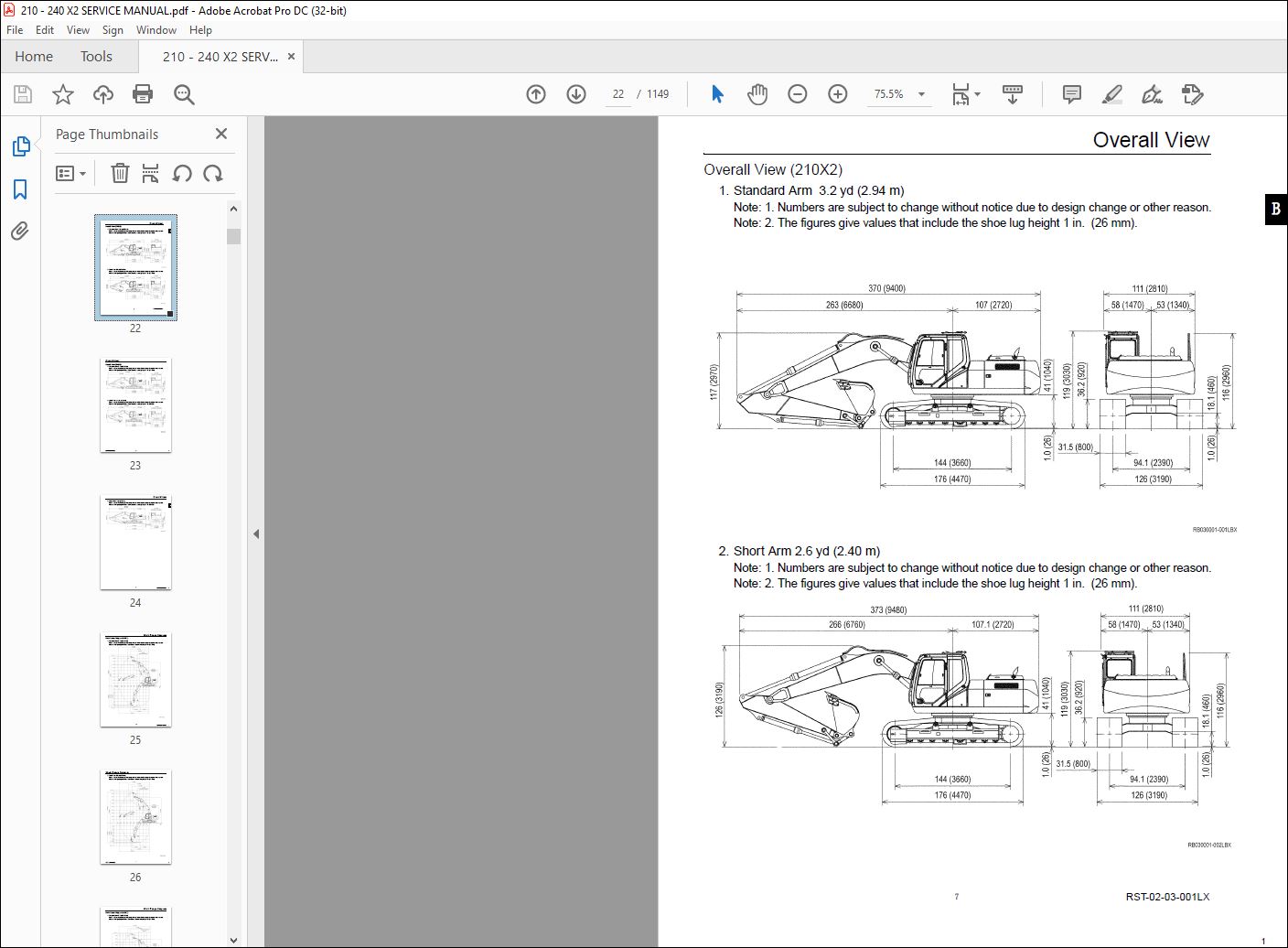
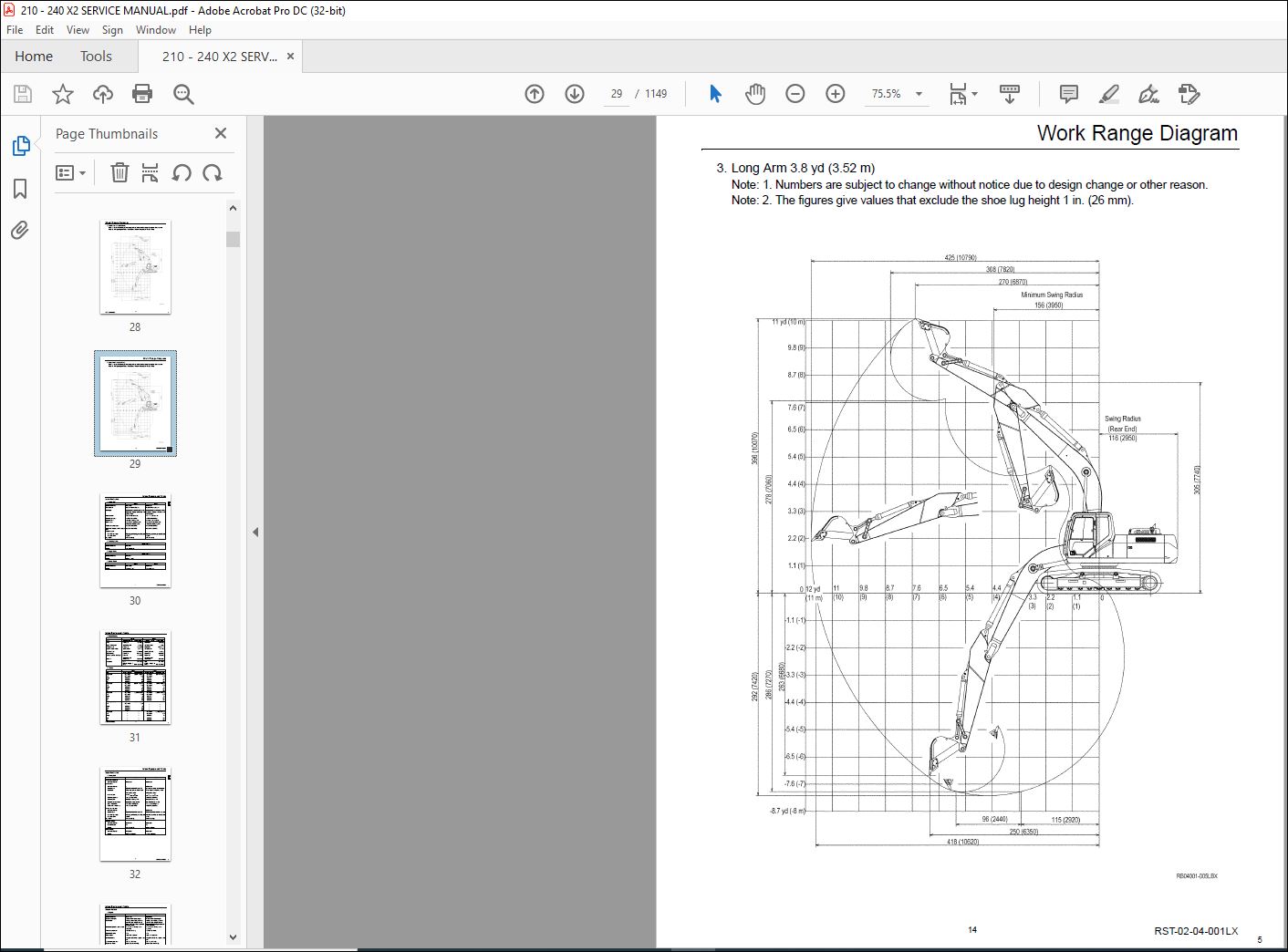
TABLE OF CONTENTS:
Linkbelt 210-240 X2 SERVICE MANUAL RST-00-00-001LX – PDF DOWNLOAD
Main Body Section
Specifications
OVERALL
1 Main Data 1
2 Performance 1
3 Main Body Dimensions1
4 Engine 2
5 Cooling System 2
6 Upper Side Work System 3
7 Operating Device3
8 Swing Units 4
9 Travel Lower Body 5
Hydraulic equipment
1 Hydraulic Device6
2 Control Valve, Cylinder 6
Capacities, filters
1 Water and Oil Capacities6
2 Hydraulic Oil Filters 7
3 Fuel Filter 7
Overall View
Overall View (210X2)
1 Standard Arm 32 yd (294 m) 8
2 Short Arm 26 yd (240 m)8
Overall View (240X2)
1 Standard Arm 33 yd (300 m) 9
2 Short Arm 27 yd (250 m)9
3 Long Arm 38 yd (352 m)9
Work Range Diagram
Work Range Diagram (210X2)
1 Standard Arm 32 yd (294 m) 10
2 Short Arm 26 yd (240 m)11
Work Range Diagram (240X2)
1 Standard Arm 33 yd (300 m) 12
2 Short Arm 27 yd (250 m)13
3 Long Arm 38 yd (352 m)14
Table of Contents
RST-00-00-001LX
Summary Section
Main Equipment Table
Lower Mechanism
1 Travel Unit1
2 Take-Up Roller1
3 Upper-Roller 1
4 Lower Roller 1
5 Recoil Spring2
6 Shoes 2
Upper Mechanism
1 Swing Unit 3
Engine-Related
1 Engine 4
2 Muffler 5
3 Air Cleaner (double element)5
4 Radiator5
Hydraulic Device
1 Hydraulic Pump 6
2 Pump P – Q Diagram7
Control-Related
1 Control Valve 9
2 Solenoid Valve (5 way) 9
3 Remote Control Valve (left / right, travel operations) 10
4 Remote Control Valve Characteristic Diagram11
5 Cushion Valve (heat circuit, with shuttle valve)12
6 Selector Valve (option) 12
7 Center Joint 13
Backhoe Attachment
1 Cylinder 14
2 Attachment 15
Equipment Layout Diagram
Main Equipment Layout 16
Consumable Part Layout 17
Table of Contents
RST-00-00-001LX
Hydraulics Section
Hydraulic Equipment Layout
Overall View1
Pump Chamber Hydraulic Equipment Layout2
Swing Body Center Section Hydraulic Equipment Layout 3
Housing Left Side Hydraulic Equipment Layout 4
Layout of Hydraulic Equipment in Cab 5
Port Diagram
Pump
1 Hydraulic Pump (standard model) 6
Valves
1 Control Valve 7
2 5-way Solenoid Valve 10
3 2-way Solenoid Valve 11
4 Remote Control Valves (upper side, travel) 12
5 Cushion Valve13
6 4-way Multi-valve 14
7 2-way Multi-valve 15
8 Direction Valve / Shut-off Valve 16
9 HBCV 17
Manifolds
1 Manifold Under Cab18
2 Manifold (accumulator section)18
3 Manifold (hydraulic oil tank section)19
Motors
1 Swing Motor 20
2 Travel Motor 22
3 Center Joint 23
Pilot Hose Connection Diagram
Pilot P and T Lines 24
Pilot Control Line 26
Pilot Control Line (2-way selector valve)28
Pilot Control Line (4-way selector valve)30
Table of Contents
RST-00-00-001LX
Function List
Function Table 32
Explanation of New Functions
1 Swing Relief Cut Control 34
2 Swing Speed Limit Control 36
3 Negative Control Power Save Control 37
4 Option Line Flow Adjustment Control 38
5 Compatible Circuit (breaker ⇔ pulverizer) One-Touch Switching Control 39
6 Bucket Close Regenerative Circuit 40
Explanation of Hydraulic Circuit and Operations (standard model)
Travel Circuits
1 Low Speed Travel Circuit 41
2 High-Speed Travel Circuit 43
3 Straight Travel Circuit45
Swing Circuits
1 Swing Speed Limit Control Circuit 47
2 Swing Relief Cut-off Control Circuit 49
3 Swing Priority Circuit 51
4 Swing Brake Circuit 53
5 Swing Parking Circuit (lever in neutral)55
6 Swing Parking Circuit (brake release) 57
7 Swing Parking Circuit (machine stop)59
Boom Circuits
1 Boom-Up Circuit (single operation) 61
2 Boom-Up Circuit (compound boom-up + arm-in) 63
3 Boom Down Regenerative Circuit 65
4 Boom Down Tilting Prevention Circuit 67
5 Boom Down Load Hold Valve Circuit69
Arm Circuits
1 Arm-Out Circuit71
2 Arm-In Forced Regenerative Circuit 73
3 Arm-in Load Hold Valve Circuit75
Bucket Circuit
1 Bucket Open Circuit77
2 Bucket Close Regenerative Circuit 79
Negative Control Circuit
1 Negative Control Circuit (power save solenoid OFF) 81
2 Negative Control Power Save Circuit (power save solenoid ON) 83
3 Negative Control Circuit (bucket close, power save solenoid OFF) 85
Table of Contents
RST-00-00-001LX
Increased Horsepower Circuits
1 Arm-In Increased Horsepower Circuit 87
2 Travel Increased Horsepower Circuit89
Other Circuits
1 Cushion Circuit
(1) Arm-out operation 91
(2) When arm-out operation stopped93
(3) Arm-out Arm-in operation95
2 Heat Circuit (lever in neutral) 97
3 Auto Power Boost Circuit (bucket close)99
Explanation of Hydraulic Circuit and Operations (option)
Option Circuit
1 Breaker Circuit (single operation) 101
2 Shuttle Circuit (hydraulic thumb) 103
3 Compatible Circuit
(1) Breaker Q control 105
(2) 2nd crusher 107
4 Second Option Circuit (hydraulic rotation fork) 109
Main Equipment Structure and Operation Explanation
Pump
1 Hydraulic Pump 111
2 Regulator113
3 Gear Pump 119
Motor
1 Travel Motor 120
2 Swing Motor 139
Valve
1 Control Valve 149
2 5-way Solenoid Valve Operation Explanation182
3 Upper Side Pilot Valve (remote control valve) 184
4 Travel Pilot Valve (remote control valve)189
5 Cushion Valve193
6 Selector Valve (4-way) (Not used by LBX) 197
7 Selector Valve (3-way)201
Table of Contents
RST-00-00-001LX
Electrical Section
Explanation of New Functions
Work Mode Select Switch1
Controller Connection Method4
Monitor Changes 5
Pilot Pressure Switch Changed to Pressure Sensor 8
Pump Proportional Valve 10
1 Horsepower Control Proportional Valve 10
2 P1 Flow Control Proportional Valve10
System Control for Energy Saving11
1 Reduced Fuel Consumption Through Transient Load Reduction Control 11
2 Reduced Fuel Consumption Through Swing Relief Cut Control 13
3 Reduced Fuel Consumption Through Power Save Control 15
Swing Speed Limit Control 17
Electrical Equipment Layout Diagram
Overall View19
1 Main Unit Right Side Layout Diagram (radiator compartment)20
2 Engine Section Layout Diagram21
3 Main Unit Left Side Layout Diagram (pump compartment) 22
4 Main Unit Center Section Layout Diagram 23
5 Cab Layout Diagram 124
6 Layout Around Operator Seat26
Stand-Alone Parts Diagram27
Main Equipment Structural Diagrams
Connection Connector Pin Layout
1 Computer 45
2 Monitor 46
Table of Contents
RST-00-00-001LX
Electrical Circuit Diagram
Overall View
1 Sequence Circuit Diagram (A3)47
Block Diagrams
1 Computer48
2 Computer S (Not used by LBX) 49
3 ECM 50
4 Monitor Display51
5 Air Conditioner52
6 Lever Lock 53
7 Horn53
8 Working Light54
9 Option54
10 Others55
11 Electrical Symbol List 56
Electrical Connector Wiring Diagram
Main Frame
1 Main Frame 57
Cab
1 Cab Main Harness58
2 Cab Sub Harness 59
3 In Cab60
Console
1 Console Right Harness 61
2 Console Left Harness61
Electrical Parts and Wiring Assembly Diagram
Main Frame62
Cab 63
Explanation of Functions and Operations
Explanation of Electrical Functions64
Engine Speed Control
1 Throttle Control66
2 Idling Control (auto / one-touch)70
3 Idling Start 71
4 Idle Up 72
5 Auto Warm Up 72
Table of Contents
RST-00-00-001LX
Engine Start / Stop Control
1 Engine Start / Stop Judgment 74
2 Power-Cut Delay75
3 Engine Emergency Stop77
4 Neutral Start 78
Pump Control
1 Work Mode Control79
2 Pump Added Horsepower Control80
3 Pump Horsepower Cut Control81
4 Power save control 82
Swing
1 Swing Brake 84
2 Swing Free Swing (option for North America) 85
3 Swing Lock (for maintenance) 86
4 Swing Relief Cut87
5 Swing Speed Limit88
Travel
1 Travel Speed Switchover 90
2 Travel Alarm91
Valve Control
1 Lever Lock 93
2 Solenoid Sticking Prevention 94
3 Pressure Boost Control 95
Monitor Control
1 Bar Graph
(coolant temperature gauge, oil temperature gauge, fuel gauge) 97
Accessories
1 Horn104
2 Working Light105
3 Wiper & Washer 106
4 Room Lamp108
5 Radio Mute 110
Others
1 Anti-Theft Protection111
2 Battery Save Function 112
3 Alternator Power Generation Detection113
4 Overload Alarm (Not used by LBX) 114
Table of Contents
RST-00-00-001LX
Options
1 Option Line Control 116
2 Option Line Control 119
3 Feed Pump Automatic Stop (Fuel Feed Pump not used on LBX machines 121
4 Return Filter Restriction Detected 124
5 Beacon 125
Service Support
Screen Operations
1 Screen Shift128
Screen Display List
1 CHK (status display) Screen List129
2 DIAG (trouble diagnosis) Screen140
3 HR (usage log) Screen List 142
4 CFG (setting change) Screen149
5 CAL (troubleshooting support) Screen 152
6 Check the Monitor Switch (monitor switch check screen) 155
7 Option Flow Setting 157
8 Anti-Theft Protection Setting 159
9 Model Setting 160
10 Engine Screen Information 162
Screen Display Details
1 Message Display List163
Abnormality Display
1 Diagnostic Trouble Code Display165
2 Main Unit Error Code Table 166
3 Diagnostic Trouble Code (Monitor display) 169
4 Sensor Trouble Operation Table 174
5 EPF (Engine Protection Feature) 176
Table of Contents
RST-00-00-001LX
Engine Section
Engine Summary
Main Data Table (changes from LX) 1
Overall Appearance Diagram2
Sensor and Auxiliary Equipment Layout (left)3
Sensor and Auxiliary Equipment Layout (rear) 4
Engine System Diagram4
Fuel System Diagram5
Detailed Parts Diagrams
1 ECM (engine control module)6
2 Supply Pump / SCV (suction control valve)7
3 Common Rail / Flow Damper 7
4 Common Rail Pressure Sensor / Pressure Limiter8
5 Injector8
6 Engine Coolant Temperature Sensor 9
7 Engine Oil Pressure Sensor 9
8 Cam Position Sensor (CMP sensor)10
9 Crank Position Sensor (CKP sensor) 10
10 Atmospheric Pressure Sensor11
11 Suction Air Temperature Sensor11
12 Boost Pressure Sensor 12
13 Boost Temperature Sensor12
14 Electromagnetic Pump 13
15 EGR Cooler 13
16 Lead Valve (check valve)14
17EGR Valve 14
Engine Control Summary 15
Explanation of Engine Terms
Function Explanation Table16
Explanation of Engine Structure
Technology for Exhaust Gases
1 Common Rail System18
2 Multi-Stage Fuel Injection (multiple injection) 19
3 Inter Cooler21
4 EGR (exhaust gas recirculation)22
Explanation of Engine Operation
Engine Overall
1 Comparison of 6BG1 and 4HK124
Fuel Unit
1 Common Rail System Summary 25
Table of Contents
RST-00-00-001LX
2 Change Points for Injection Method (governor, common rail)26
3 Explanation of Injector Operation 27
4 Explanation of Supply Pump Operation30
5 Supply Pump Disassembly Diagram31
6 Explanation of Flow Damper Operation32
7 Pressure Limiter 33
8 Cautions for Maintenance34
Explanation of Engine Control
1 Fuel Injection Quantity Correction 37
2 Starting Q Correction37
3 Pre-Heat Control (QOS quick on start)37
4 Atmospheric Pressure Correction (high altitude correction)37
5 Control for Overheating 38
6 Control for Boost Temperature Rise 39
7 Control for Engine Oil Pressure Drop 39
8 Start Control (coolant temperature monitoring) 39
9 Long Cranking Control 40
10 Starting Control for Reduced Number of Cylinders 40
11 Normal Stop (key switch OFF operation) 40
12 Engine Start / Stop Judgment 41
Engine Maintenance Standards
Engine Information Screen 42
Monitor Operation Method43
Engine Information (Q adjustment, QR code, engine serial number)
Copying Method44
Rewriting Injector QR Codes 45
When Replacing Controller A at the Same Time47
Engine Information Acquisition Timing 47
Trouble Display 47
Engine Equipment Table
Exhaust Gas Third Regulation Accessory Electrical Parts Compatibility
(ISUZU part number) 48
Exhaust Gas Regulations
Features of Materials Subject to Exhaust Gas Regulation 49
Exhaust Gas Regulation Values 49
Cautions for Fuel Used
Engine Fuel and Maintenance of Fuel Filters 51
1 Fuel to be applied 51
2 Maintenance of fuel filters 52
Table of Contents
RST-00-00-001LX
Air Conditioner Section
Changes from LX
Change List 1
Layout Diagram
Air Conditioner Overall Diagram
1 Frame 2
2 Cab3
Equipment Layout Diagram 5
Explanation of Functions
Explanation of Control 7
1 Air Mix Motor Actuator Control 8
2 Blow Mode Motor Actuator Control8
3 Refresh / Recirculate Switch Motor Actuator Control 9
4 Blower Amp Control10
5 Compressor Clutch Control 13
6 COOLMAX Control and HOTMAX Control 14
7 Trouble Detection and Control after Trouble Detected15
8 Monitor Mode 17
9 Door Switch Control 18
10 Inside Air Filter Clogging Detection Control 19
Actuator Inspection
Air Mix Motor Actuator Inspection21
Refresh / Recirculate Motor Actuator Inspection 23
Mode Motor Actuator Inspection25
Self-Diagnosis Function With Panel Display
Trouble Display and Self-Check Procedure
1 Trouble Display Position 27
2 Explanation of Trouble Display 27
3 Explanation of Monitor Mode29
Part Function and OK / NG Judgment
Control Panel and Control Unit 38
Blower Amp 38
Relay39
Air Mix Actuator 39
Refresh / Recirculate Actuator40
Blow Mode Actuator40
Evaporator Sensor41
Dual Pressure Switch 41
Solar Radiation Sensor41
Table of Contents
RST-00-00-001LX
Maintenance Section
Pressure Measurement and Adjustment Procedures
Procedures for pressure measurement from the monitor display1
Monitor and switch panel
1 Pressure Measurement Method 1
2 Operating Method1
Procedures for measuring hydraulic oil temperature from the monitor display
1 Hydraulic Oil Temperature Measurement Method 2
2 Operating Method2
Procedures for pressure measurement by installing pressure gauge
1 Preparations 3
2 Items to Prepare3
Pressure measuring ports 4
Control valve5
Pressure measurement preparations 6
Pressure measurement and adjustment procedures
1 Main Pressure Measurement 9
2 Pilot Pressure Measurement 13
3 Negative Control Pressure Measurement 14
Pressure adjustment
1 Main Pressure Adjustment 15
2 Pilot Pressure Adjustment 18
Hydraulic Pump Flow Measurement Procedure
Preparations 19
1 Items to Prepare19
Work preparations 20
Flow measurement 23
Drain Volume Measurement Procedure
Preparations 24
Travel motor drain volume measurement24
Swing motor drain volume measurement 27
Air Bleed Procedure
Hydraulic pump28
Travel motor 29
Swing motor30
HBCV31
1 Boom Cylinder HBCV31
2 Arm Cylinder HBCV31
Table of Contents
RST-00-00-001LX
Procedures for Replacing Consumable Parts
Air conditioner belt, fan belt replacement
1 Air Conditioner Belt Replacement 32
2 Fan Belt Replacement 34
Fuel filter replacement
1 Filter Replacement 37
2 Air Bleeding 39
Engine oil filter and engine oil replacement
1 Engine Oil Replacement40
2 Engine Oil Filter Replacement41
Radiator coolant replacement43
Air cleaner cleaning and replacement 44
Hydraulic oil filter replacement45
1 Return Filter Replacement 46
2 Suction Filter Replacement 47
3 Air Breather Element Replacement48
4 Pilot Oil Filter Replacement48
5 Hydraulic Oil Replacement 49
Others
1 Coolant Filling52
2 Washer Fluid Filling 52
Lever Pattern Change Procedure
Items to prepare
ISO type 53
ISO type ⇒ SUMITOMO type 54
ISO type ⇒ MITSUBISHI type 54
ISO type ⇒ SHINKO type 55
Periodic Maintenance Procedures
Maintenance every 250 hours 56
1 Battery Inspection and Replacement 56
Maintenance after first 250 hours for new machine / every 1000 hours from then ON
1 Swing Reduction Gear Oil Replacement57
2 Gear Oil Filling58
3 Replace the Flange Packing at the Bottom of the Fuel Tank59
Bolt Size and Torque Table
Bolt and nut tightening60
Retightening torque table61
Table of Contents
RST-00-00-001LX
Data Section
Main Unit Weight
Major Component Weight (standard specifications) 1
Individual Part Weight2
Dry weight for each part is shown in the table below2
Shoe Weight (per side) 2
Arm Weight 2
Bucket Weight3
Compatibility
Compatibility 4
1 Main Part Interchangeability Table (210X2)4
2 Main Part Interchangeability Table (240X2)5
Attachment Installation Methods
Attachment Dimensions8
Paint Colors
Paint Colors 9
Unit Conversion Ratio
Unit Conversion Ratio10
VIDEO PREVIEW OF THE MANUAL:
PLEASE NOTE:
- This is the SAME exact manual used by your dealers to fix your vehicle.
- The same can be yours in the next 2-3 mins as you will be directed to the download page immediately after paying for the manual.
- Any queries / doubts regarding your purchase, please feel free to contact [email protected]
I.G


