

Liebherr Tractor RL 46 1631 3A Pipe Layer Service Manual – PDF DOWNLOAD
FILE DETAILS:
Liebherr Tractor RL 46 1631 3A Pipe Layer Service Manual – PDF DOWNLOAD
Language : English
Pages : 793
Downloadable : Yes
File Type : PDF
Size: 166 MB
DESCRIPTION:
Liebherr Tractor RL 46 1631 3A Pipe Layer Service Manual – PDF DOWNLOAD
This Service manual is intended for trained specialist staff in the Liebherr organization and its dealers.
The Service manual provides specific knowledge for the maintenance of Liebherr construction machinery. Basic technical knowledge of electrics, hydraulics, mechanics and Diesel engine technology are not detailed in this Service manual. A subject-based, qualified training is therefore necessary. Liebherr recommends participation on the Liebherr Training program for construction machinery.
In this Service manual you find information about:
For information relating to control and operation refer to the operator’s manual. For information relating to spare parts refer to the Spare parts catalog. Observe the locally applicable accident prevention regulations.
- Familiarize yourself with the operator’s manual before putting the machine into service. Also, ensure you have obtained, read, and understood any additional instructions regarding special accessories for the machine.
- Only authorized personnel may operate, maintain, or repair the machine. Remember to observe the minimum legal age limit.
- Utilize trained or instructed personnel and clearly define their responsibilities for operation, setup, maintenance, and repairs.
- Determine the machine operator’s responsibility, including adherence to traffic regulations, and empower them to refuse unsafe instructions from third parties.
- Do not allow untrained or trainee individuals to operate or work on the machine without constant supervision and guidance from an experienced instructor or operator.
- Periodically check and observe anyone operating or working on the machine to ensure they follow the safety instructions and guidelines provided in the operator’s manual.
- Always wear appropriate work clothing when operating or working on the machine. Avoid wearing rings, watches, ties, scarves, open jackets, or loose clothing that may pose a risk of injury by getting stuck or pulled in. Use prescribed safety equipment for specific tasks, such as safety glasses, safety shoes, safety helmets, work gloves, reflective vests, and ear protection.
- Consult the supervisor at the jobsite for special safety instructions and regulations.
- Maintain three-point contact when entering and exiting the machine.
- Never use joysticks as handholds when entering or exiting the machine to prevent inadvertent movement and serious accidents.
- Avoid jumping off the machine. Use designated steps, ladders, catwalks, and handles when climbing on or off the machine. Use both hands for support and face the machine.
- Keep steps, ladders, and handles free of oil, grease, mud, snow, and ice to minimize the risk of slipping, stumbling, or falling.
- Familiarize yourself with the emergency exit.
- If no other instructions are provided, follow this procedure for maintenance and repair work:
- Park the machine on solid and level ground.
- Bring all control levers to the neutral position.
- Set the parking switch to the park position.
- Turn off the engine and remove the ignition key.
- Actuate the control levers several times to relieve pressure in the servo lines.
- Bring all control levers to the neutral position.
- Before working on the hydraulic circuit, with the engine turned off and the ignition key in the contact position, move all pilot controls (joysticks and pedals) in both directions to relieve servo pressure and remaining back pressures in the working circuits. Then release the internal hydraulic tank pressure.
- Before leaving the operator’s seat, switch the parking switch to the park position.
- Secure all loose parts on the machine.
- Never operate the machine without conducting a complete walk-around inspection. Check if all warning signs are present on the machine and if they are legible.
- Observe all signs indicating danger and safety instructions.
IMAGES PREVIEW OF THE MANUAL:
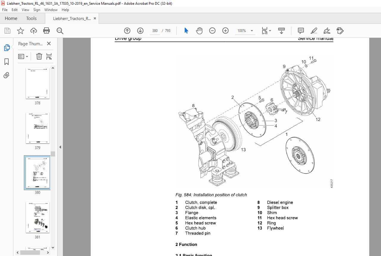
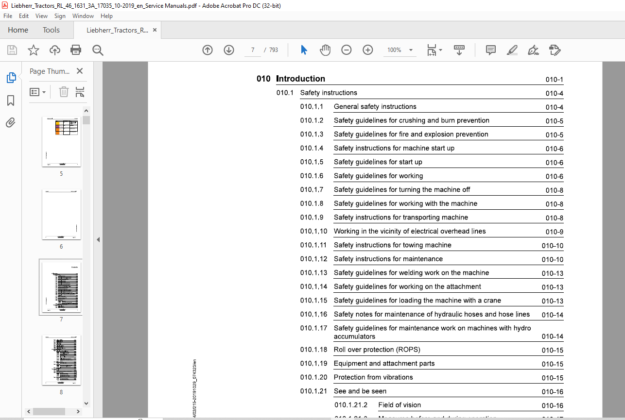
TABLE OF CONTENTS:
Liebherr Tractor RL 46 1631 3A Pipe Layer Service Manual – PDF DOWNLOAD
010.1 Safety instructions 010-4
0101.1 General safety instructions 010-4
010.1.2 Safety guidelines for crushing and burn prevention 010-5
010.1.3 Safety guidelines for fire and explosion prevention 010-5
010.14 Safety instructions for machine start up 010-6
0101.5 Safety guidelines for start up 010-6
010.1.6 Safety guidelines for working 010-6
0101.7 Safety guidelines for turning the machine off 010-8
010.1.8 Safety guidelines for working with the machine 010-8
010.1.9 Safety instructions for transporting machine 010-8
010.1.10 Working in the vicinity of electrical overhead lines 010-9
010.1.11 Safety instructions for towing machine 010-10
010.1.12 Safety instructions for maintenance 010-10
010.1.13 Safety guidelines for welding work on the machine 010-13
010.1.14 Safety guidelines for working on the attachment 010-13
010.1.15 Safety guidelines for loading the machine with a crane 010-13
010.1.16 Safety notes for maintenance of hydraulic hoses and hose lines 010-14
010.1.17 Safety guidelines for maintenance work on machines with hydro
accumulators 010-14
010.1.18 Roll over protection (ROPS) 010-15
010.1.19 Equipment and attachment parts 010-15
010.1.20 Protection from vibrations 010-15
010.1.21 See and be seen 010-16
010.1.21.2 Field of vision 010-16
010.1.21.3 Measures before and during operation 010-17
010.1.22 Safety notes for working on Common Rail System of Diesel engine€10-18
010.2 Special tools for maintenance and repair work 010-20
0102.1 Tools – Diesel engine 010-20
0102.2 Tools – Hydraulic system 010-22
010.2.4 Tools – Electrical system 010-28
010.2.5 Tools – Travel gearbox 010-30
010.2.6 Tools – Travel gear 010-31
010.2.7 Tension unit tools 010-32
010.2.8 Tools – Oscillating axle frame 010-32
010.2.9 Tools, operator’s platform 010-33
010.2.10 Tools – Diesel exhaust fluid system 010-33
Standards and specifications 010-35
010.3.1 Preload values and tightening torques for screws with standard and
fine metric thread according to DIN 1SO 261 010-35
010.3.1.1 Scope of application and purpose 010-35
010.3.1.2 Further applicable documentation 010-35
010.3.1.3 Changes and descriptions 010-36
010.3.1.4 Tightening values 010-36
010.3.1.5 Flanges and half flanges for high pressure (standard
62) 010-42
010.3.1.6 Half flange for low pressure (standard 61) 010-42
010.3.1.7 Tightening torques for cutting edges, end bits and
adapters 010-42
010.3.2 Installation specifications 010-43
010.3.2.1 Duo cone slipring seals 010-43
010.3.3 Tapping bores 010-45
010.3.3.1 Tapping bores of metric ISO standard threads 010-45
010.3.3.2 Tapping bores of metric ISO fine threads 010-47
010.3.4 Conversion tables 010-50
Conservation guidelines 010-51
010.41 General 010-51
010.4.2 Taking the machine out of service for an unknown duration 010-51
010.4.3 Shut down of the machine 010-52
010.4.3.1 Shut down for up to 2 months 010-52
010.4.3.2 Shut down for up to 12 months 010-53
010.4.3.3 Shut down for longer than 12 months 010-54
010.4.4 Return to operation 010-54
0104.41 After a shut down of 2 months 010-54
010.442 After a shut down of 12 months 010-54
010.4.4.3 After shut down of longer than 12 months 010-55
010.5 Repair welding 010-56
010.5.1 Preparation of cracked part 010-56
010.5.1 Preparation of a weld 010-57
010.5.1 Treatment of electrodes 010-57
010.5.1 Welding technique 010-57
010.5.1 Reinforcement of welding seam 010-58
010.5.1 General use of reinforcement sheeting 010-58
010.5.1.1 Form of sheeting 010-58
010.5.1.1 Thickness of sheeting 010-58
010.5.1.1 Material quality of sheeting 010-59
010.5.1.1 Application of reinforcement sheeting 010-59
010.5.1.1 Welding the reinforcement sheeting 010-59
010.5.1.1 Selection of correct welding electrodes 010-60
010.5.1.2 Electrode selection 010-60
010.5.1.2 Steel chart 010-61
010.5.1.2 Welding additives chart 010-62
010.6 Hydraulic symbols 010-66
010.7 Electrical symbols 010-76
010.8 Material weights 010-80
020 Technical data 020-1
020.1 Overall machine 020-3
020.1.1 Complete machine – Overview
RL46-1631-3A/17035-; 020-3
020.2 Drive group 020-5
020.2.1 Diesel engine
RL46-1631-3A/17035-; 020-5
020.3 Cooling system 020-7
020.3.1 Gear pump for cooling circuit
RL46-1631-3A/17035-; 020-7
020.3.2 Fan drive gear motor for water, charge air and hydraulic oil cooler
020.4 Working hydraulics 020-8
RL46-1631-3A/17035-; 020-8
020.44 Counterweight pilot control unit
020.4.5 Hoist gear variable displacement motor
020.46 Boom cylinder
020.4.7 Lift cylinder counterweight
Travel hydraulics 020-11
020.5.1 Replenishing gear pump and working hydraulic pilot control
020.5.2 Variable displacement pump
020.5.3 Variable displacement motor
Hydraulic components 020-12
020.6.1 Hydraulic tank
Electrical system 020-13
020.7.1 Batteries – Installation
Travel gearbox 020-14
020.8.1 Travel gearbox
020.8.2 Brake system
Travel gear, axles, tyres, drive shafts 020-16
020.9.1 Travel gear frame
020.9.2 Idler
020.9.3 Tension unit
020.9.4 Track roller
020.9.5 Carrier roller
020.9.6 Track chain
020.9.7 Sprocket
020.10.1 Hoist gear
RL46-1631-3A/17035-; 020-19
020.10.2 Counterweight
RL46-1631-3A/17035-; 020-19
020.11 Working attachment 020-20
020.11.1 Hook block
RL46-1631-3A/17035-; 020-20
020.11.2 Rope winch
RL46-1631-3A/17035-; 020-20
030 Maintenance 030-1
030.1 Maintenance and inspection schedule 030-8
030.2 Fill quantities, lubrication schedule 030-14
030.2.1 Recommended lubricants
RL46-1631-3A/17035-; 030-14
03022 Recommended fuel and operating fluids
RL46-1631-3A/17035-; 030-14
030.2.3 Lubrication schedule
RL46-1631-3A; 030-15
030.3 Lubricants and fuels 030-18
030.3.1 General information about lubricants and fuels 030-18
030.3.1.1 General Information 030-18
030.3.1.2 General questions 030-18
030.3.1.3 Safety data sheets 030-18
030.3.1.4 Technical data sheets 030-18
030.3.1.5 Specific Liebherr standards 030-18
030.3.2 Diesel fuels
RL46-1631-3A/17035-; 030-19
030.3.2.1 Minimum quality requirement 030-19
030.3.3 Engine oils
RL46-1631-3A/17035-; 030-19
030.3.3.1 Liebherr recommendation 030-19
030.3.3.1 Other approved engine oils 030-19
030.3.3.2 Minimum quality requirement 030-19
030.3.3.3 Aggravating circumstances 030-20
030.34 Coolant
RL46-1631-3A/17035-; 030-20
030.3.4.2 Corrosion inhibitor 030-20
030.3.4.2 Liebherr recommendation 030-20
030.3.4.2 Anti-freeze and corrosion protection agent 030-21
030.3.4.2 Liebherr recommendation 030-21
030.3.4.2 Minimum quality requirement 030-21
030.3.5 Hydraulic oil
RL46-1631-3A/15374-; 030-21
030.3.5.1 Liebherr Hydraulic oil 030-21
030.3.5.2 Engine oil as hydraulic oil 030-22
030.3.5.3 Warm up specification 030-23
030.3.5.4 Biodegradable hydraulic oils 030-23
030.3.5.5 Oil change, oil analysis, filter change 030-24
030.3.6 Lube oils for travel gearbox
RL46-1631-3A/15374-; 030-26
030.3.6.1 Quality 030-26
030.3.6.2 Viscosity 030-27
030.3.6.3 Oil change 030-27
030.3.7 Qil for duo cone (slipring) seal Travel gear
RL46-1631-3A; 030-28
030.3.8 Lube oils for hoist winch
RL46-1631-3A/17035-; 030-28
030.3.8.1 Freefall and oil motor side 030-28
030.3.9 Lubricants for the hoist rope
RL 46-1631-3A/17035-; 030-28
030.3.10 Grease and other lubricants
RL46-1631-3A/17035-; 030-28
030.3.11 Qil for hinges and joints
RL46-1631-3A; 030-30
030.3.12 Qil for axle bearing
RL46-1631-3A; 030-30
030.4 Maintenance tasks 030-31
030.4.1 Safety instructions for maintenance
RL46-1631-3A; 030-31
030.4.2 Maintenance – preparations 030-31
030.4.2.1 Maintenance position
RL46-1631-3A/17035-; 030-31
030.4.2.2 Turn the electrical system off
RL46-1631-3A/17035-; 030-35
030.4.2.3 Raising the operator’s cab hydraulically
RL46-1631-3A/17035-; 030-35
RL46-1631-3A/17035-; 030-37
030.4.3 Overall machine 030-39
030.4.3.1 Checking the machine for external damage, correct
maintenance and proper condition
RL46-1631-3A/17035-; 030-39
030.4.3.2 Lubricating all lube points according to lubrication
chart
RL46-1631-3A/16374-; 030-39
030.4.3.3 Checking the window wiper
RL46-1631-3A/17035-; 030-40
030.4.3.4 Oil samples and oil analysis
RL46-1631-3A/15374-; 030-40
030.4.3.5 Take an oil sample on the hoist winch
RL46-1631-3A/17035-; 030-44
030.4.3.6 Wet cleaning the machine
RL46-1631-3A/17035-; 030-45
030.4.3.7 Protecting the piston rods
RL46-1631-3A/17035-; 030-46
030.4.3.8 Taking the machine out of service
RL46-1631-3A; 030-47
030.44 Drive group 030-47
030.4.4.1 Check the engine oil level
RL46-1631-3A/17035-; 030-47
030.4.4.2 Changing engine oil
RL46-1631-3A/17035-; 030-48
030.4.4.3 Changing the lube oil filters
RL46-1631-3A/17035-; 030-49
030.4.4.4 Diesel engine: Check the arrangement and belly
pans for contamination and clean
RL46-1631-3A/17035-; 030-50
030.44.5 Checking ribbed V-belt and adjusting it if necessary
RL46-1631-3A; 030-51
030.44.6 Changing belt drive
RL46-1631-3A/15374-; 030-53
030.4.4.7 Checking diesel engine configuration for leaks and
condition
RL46-1631-3A/17035-; 030-54
030.44.8 Check the supply and exhaust lines for mounting and
leaks
RL46-1631-3A/17035-; 030-54
030.4.4.9 Check the electrical system of the Diesel engine
RL46-1631-3A/17035-; 030-55
030.4.4.10 Change oil separator filter cartridge
RL46-1631-3A/17035-; 030-5
RL46-1631-3A/17035-; 030-56
030.4.4.12 Checking engine mount, oil pan and engine brackets
RL46-1631-3A/15374-; 030-58
030.4.4.13 Notes for work on the fuel system
RL46-1631-3A/17035-; 030-58
030.4.4.14 Fuel preliminary filter: Drain the condensation
RL46-1631-3A/17035-; 030-59
030.4.4.15 Fuel tank: draining condensation and sediments
RL46-1631-3A/15374-; 030-59
030.4.4.16 Change fuel preliminary filter cartridge
RL46-1631-3A/15374-; 030-61
030.4.4.17 Changing fuel fine filter
RL46-1631-3A/15374-; 030-62
030.4.4.18 Emptying and cleaning the fuel tank
RL46-1631-3A/15374-; 030-64
0304.4.19 Venting fuel system
RL46-1631-3A/15374-; 030-66
030.4.4.21 Replacing the air filter
RL46-1631-3A/17035-; 030-68
030.4.4.22 Clean the dust discharge valve
RL46-1631-3A/17035-; 030-71
030.4.5 Cooling system 030-72
030.4.5.1 Check the coolant level
RL46-1631-3A/17035-; 030-72
030.4.5.2 Cleaning the cooling system
RL46-1631-3A/17035-; 030-74
030.4.5.3 Check the cooling system
RL46-1631-3A/15374-; 030-75
0304.5.4 Check the antifreeze concentration in the coolant.
RL46-1631-3A/17035-; 030-76
0304.5.5 Changing coolant
RL46-1631-3A/15374-; 030-83
030.4.6 Travel hydraulics 030-85
030.4.6.1 Changing supply circuit filter
RL46-1631-3A/15374-; 030-85
030.4.7 Hydraulic components 030-89
0304.71 Checking the oil level in the hydraulic tank and
topping up oil
RL46-1631-3A/15374-; 030-89
0304.7.2 Clean the magnetic rod on the hydraulic tank
RL46-1631-3A/17035-; 030-92
0304.7.3 Checking the hydraulic system for function and leaks
RL46-1631-3A/15374-; 030-93
RL46-1631-3A/17035-; 030-94
030.4.7.5 Draining water and sediments in the hydraulic tank
RL46-1631-3A/17035-; 030-96
030.4.7.6 Change the return filter insert
RL46-1631-3A/17035-; 030-97
030.4.8 Electrical system 030-99
030.4.8.1 Check the display unit and lighting
RL46-1631-3A/15374-; 030-99
030.4.8.2 Checking batteries
RL46-1631-3A/15374-; 030-99
0304.9 Travel gearbox 030-101
030.4.9.1 Travel gearbox: checking the condition
RL46-1631-3A; 030-101
030.4.9.2 Checking the oil level
RL46-1631-3A/15374-; 030-101
030.4.9.3 Changing the oil
RL46-1631-3A/156374-; 030-102
030.4.9.4 Checking oil level in the duo cone (slip ring) area
RL46-1631-3A/15374-; 030-103
030.4.9.5 Change the oil in the duo cone (slip ring) area
RL46-1631-3A/17035-; 030-104
030.4.10 Travel gear, axles, tyres, drive shafts 030-109
030.4.10.1 Checking the nuts and bolts of the travel gear
components are firmly seated
RL46-1631-3A/17035-; 030-109
030.4.10.2 Checking the carrier rollers, track rollers and idlers
for tightness
RL46-1631-3A/15374-; 030-111
030.4.10.3 Check and adjust the idler guides
RL46-1631-3A/17035-; 030-111
030.4.104 Checking track tension and adjusting, if necessary
RL46-1631-3A/17035-; 030-115
030.4.10.5 Changing track
RL46-1631-3A/17035-; 030-118
030.4.10.6 Checking the travel gear wear
RL46-1631-3A/15374-; 030-124
030.4.10.7 Checking oil fill of axle bearings
RL46-1631-3A/15374-; 030-124
0304.11 Steel components Basic machine 030-125
030.4.11.1 Checking boom equipment
RL46-1631-3A/17035-; 030-125
030.4.11.2 Checking function of free fall device
RL46-1631-3A/17035-; 030-126
030.4.11.3 Checking rope pulleys and hook block for wear and
function
RL46-1631-3A/17035-; 030-127
030.4.11.4 Check function of hoist limit switch of hook block
RL46-1631-3A/17035-; 030-127
0304.11.5 Checking entire length of winch rope for damage and
greasing if necessary (observe operator’s manual of
rope manufacturer)
RL46-1631-3A/17035-; 030-128
030.4.12 Working attachment 030-135
0304.12.1 Checking bearing points of working attachment for
play and wear
RL46-1631-3A/17035-; 030-135
030.4.12.2 Maintenance tasks on the hoist winch
RL46-1631-3A/17035-; 030-135
0304.12.3 Checking the mounting screws and bolt retainers of
the working attachment for tight seating
RL46-1631-3A/17035-; 030-140
030.4.13 Operator’s cab, heating, air conditioning 030-141
030.4.13.1 Checking heating and air conditioning for function
and checking heating for leaks
RL46-1631-3A/15374-; 030-141
0304.13.2 Checking recirculated air filter and changing it if
necessary
RL46-1631-3A/15374-; 030-141
030.4.13.3 Checking heating fresh air filter and changing it if
necessary
RL46-1631-3A/15374-; 030-142
030.4.13.4 Inspection of the air conditioning system by HVAC
specialist staff
RL46-1631-3A/15374-; 030-143
030.4.13.5 Checking drier unit (moisture, fill, condition) – if
necessary, renew drier unit, evacuate system and
refill
RL46-1631-3A/15374-; 030-143
030.4.13.6 Checking drain valves for the air conditioning and
cleaning them if necessary
RL46-1631-3A/15374-; 030-144
030.4.13.7 Checking condenser for contamination and clean it, if
necessary
RL46-1631-3A/15374-; 030-145
030.4.13.8 Checking cable routings and connections
RL46-1631-3A/15374-; 030-145
030.5 Testing and adjustment checklist
RL46-1631-3A/17035-; 030-146
030.5.1 Adjustment checklist 030-146
030.5.2 Track Components Check List 030-158
030.5.2.1 Test report 030-158
030.5.2.2 Wear data 030-162
030.6 Check and adjustment tasks 030-165
0306.1 Safety instructions
RL46-1631-3A; 030-165
030.6.2 Overall machine 030-166
030.6.2.1 Preparations for adjustment procedures
RL46-1631-3A/17035-; 030-166
030.6.2.2 Visual inspection and maintenance
RL46-1631-3A/17035-; 030-168
030.6.2.3 Bringing machine to operating temperature
RL46-1631-3A/17035-; 030-169
030.6.2.3 Various procedures can be selected for reaching the
operating temperature:
RL46-1631-3A/17035-; 030-169
0306.3 Drive group 030-170
030.6.3.1 Engine speed controller of diesel engine — deter-
mining adjustment range
RL46-1631-3A/17035-; 030-170
0306.4 Cooling system 030-173
030.6.4.1 Checking pressure relief valve — fan motor and fan
control
RL46-1631-3A/17035-; 030-173
0306.5 Working hydraulics 030-178
030.6.5.1 Checking the standby pressure
RL46-1631-3A/17035-; 030-178
030.6.5.2 Checking the primary pressure relief valve on the
control valve block
RL46-1631-3A/17035-; 030-178
030.6.5.3 Checking secondary pressure relief valve
RL46-1631-3A/17035-; 030-179
030.6.5.4 Checking pressure cut off valves 106 on regulating
pump and LS pressure cut off 159 on control valve
block
RL46-1631-3A/17035-; 030-183
030.6.5.5 Freefall function
RL46-1631-3A/17035-; 030-185
030.6.5.6 Checking the pressure difference HD-LS
RL46-1631-3A/17035-; 030-187
030.6.5.7 Checking the nitrogen fill in the hydro accumulator
RL46-1631-3A/17035-; 030-187
030.6.5.8 Venting the control valve block
RL46-1631-3A/17035-; 030-189
0306.6 Travel hydraulics 030-190
RL46-1631-3A/17035-; 030-190
030.6.6.2 Checking hydraulic neutral position of variable
displacement pump
RL46-1631-3A/17035-; 030-192
0306.6.3 Checking the pressure limitation for high pressure
RL46-1631-3A/17035-; 030-194
030.6.6.4 Checking the pressure regulator
RL46-1631-3A/17035-; 030-196
030.6.7 Electrical system 030-199
030.6.7.1 Calibrating the hydrostat
RL46-1631-3A/17035-; 030-199
030.6.7.2 Checking travel joystick
RL46-1631-3A/17035-; 030-210
030.6.7.3 Calibrating inching brake pedal
RL46-1631-3A/17035-; 030-223
030.6.7.4 Brake test
RL46-1631-3A/17035-; 030-230
030.6.7.5 Overspeed safety test (option)
RL46-1631-3A/17035-; 030-234
030.6.7.6 Parameter adjustment options
RL46-1631-3A/17035-; 030-236
040 Drive group 040-1
040.1 Diesel engine 040-2
040.1.2 Fuel system 040-7
040.1.2.1 Fuel system
RL46-1631-3A/17035-; 040-7
040.1.2.2 Fuel quantity sensor
RL46-1631-3A/17035~; 040-8
040.1.2.3 Fuel filter
RL46-1631-3A/17035-; 040-9
040.1.2.4 Fuel tank
RL46-1631-3A/17035~; 040-9
040.1.3 Air filter system 040-10
040.1.3.1 Air filter system
RL46-1631-3A/17035~; 040-11
040.1.4 Diesel engine mounting
RL46-1631-3A/17035-; 040-13
040.2 Clutch
RL46-1631-3A/17035-; 040-14
050 Cooling system 050-1
050.1 Complete cooling system
RL46-1631-3A/17035-; 050-2
050.2 Cooler arrangement 050-6
0502.1 Combi cooler
RL46-1631-3A/17035-; 050-7
050.3 Hydraulic 050-13
050.3.1 Gear pump
RL46-1631-3A/17035-; 050-13
050.3.2 Gear motor
RL46-1631-3A/17035-; 050-14
060 Working hydraulics 060-1
060.1 Full overview — working hydraulic
RL46-1631-3A/17035-; 060-2
060.2 Regulating pump 060-16
0602.1 Regulating pump – full overview
RL46-1631-3A/17035-; 060-16
060.3 Proportional control valve block 060-24
060.3.1 Proportional control valve block – full overview
RL46-1631-3A/17035-; 060-25
060.4 Pilot control Working hydraulic 060-30
0604.1 Pilot control unit – Full overview
RL46-1631-3A/17035-; 060-30
060.5 Variable displacement motor Hoist gear 060-37
060.5.1 Variable displacement motor hoist gear winch
RL 46-1631-3A/17035-; 060-37
060.6 Hydraulic cylinder 060-45
060.6.1 Lift cylinder counterweight
RL46-1631-3A/17035-; 060-45
070 Travel hydraulics 070-1
070.1 Travel hydraulics overview
RL46-1631-3A/17035-; 070-2
070.2 Variable displacement motors 070-13
070.2.1 Variable displacement motors – full overview
RL46-1631-3A/17035-; 070-13
070.3 Distributor block 070-21
070.3.1 Parking brake, solenoid valve
RL46-1631-3A/17035~; 070-22
070.3.2 Pressure relief valve – replenishing
RL46-1631-3A/17035-; 070-24
080 Hydraulic components 080-1
080.1 Hydraulic cylinder 080-2
080.1.1 Boom cylinder
RL46-1631-3A/17035-; 080-2
080.1.2 Lift cylinder counterweight
RL46-1631-3A/17035-; 080-3
080.1.3 Valves
RL46-1631-3A/17035-; 080-4
080.2 Hydraulic tank 080-17
080.2.1 Hydraulic tank
RL46-1631-3A/17035-; 080-17
100 Brake system 100-1
100.1 Inching brake pedal 100-2
100.1.1 Speed reduction pedal
RL46-1631-3A/17035-; 100-2
110 Electrical system 110-1
110.1 Electrical system – full overview
RL46-1631-3A/17035-; 110-3
110.2 Lighting system
RL46-1631-3A/17035-; 110-6
110.3 Circuit diagrams
RL46-1631-3A/17035-; 110-9
110.4 Electrical components of operator’s cab 110-10
110.4.1 Cab electrical components – Full overview
RL46-1631-3A/17035-; 110-10
110.42 Travel sensor
RL46-1631-3A/17035-; 110-16
110.4.3 Speed control
RL46-1631-3A/17035-; 110-19
110.5 Electrical components – Diesel engine
RL46-1631-3A/17035-; 110-21
110.6 Electrical components – Main frame
RL46-1631-3A/17035-; 110-24
110.7 Electrical components Compartments 110-29
110.7.1 Battery compartment
RL46-1631-3A/17035-; 110-29
110.7.3 Central electrical system compartment
RL46-1631-3A/17035-; 110-33
110.7.4 Hydraulic tank
RL46-1631-3A/17035-; 110-39
110.8 Display unit
RL46-1631-3A/17035-; 110-40
110.9 Electrical components LiTU3 (option)
RL46-1631-3A/17646-; 110-41
110.10 Overload warning device display
RL46-1631-3A/17035-; 110-42
110.11 Putting overload warning device into service
RL46-1631-3A/17035-; 110-45
110.11.1.1 Preparation 110-45
110.11.1.2 Putting into service procedure 110-47
110.12 Electrical components – Main frame
RL46-1631-3A/17035-; 110-57
120 Travel gearbox 120-1
120.1 Travel gearbox, overall
RL46-1631-3A/17035-; 120-2
120.2 Brake system
RL46-1631-3A/17035-; 120-7
120.3 Duo cone slipring seal
RL46-1631-3A/17035-; 120-8
120.4 External oil supply
RL46-1631-3A/17035-; 120-9
130 Travel gear, axles, tyres, drive shafts 130-1
130.1 Travel gear frame 130-3
130.1.1 Support frame
RL46-1631-3A/17035-; 130-3
130.2 Idler
RL46-1631-3A/17035-; 130-5
130.3 Tension unit
RL 46-1631-3A/17035-; 130-7
130.4 Tension unit — removal
RL46-1631-3A/17035-; 130-9
130.4.1.1 Remove the cover on the track roller frame 130-10
130.4.1.2 Position of tension unit grease nipple 130-11
130.4.1.3 Push the pin in 130-11
130.4.1.4 Removal of cover 130-12
130.4.1.5 Grease nipple with twist guard 130-12
130.4.1.6 Place a mark 130-13
130.4.1.7 Installation of the assembly tool 130-13
130.4.1.8 Adjust the assembly tool 130-14
1304.19 Clamp on the assembly tool 130-14
130.4.1.10 Press in the tension unit 130-15
130.4.1.11 Removal of the tension unit 130-16
130.5 Tension unit — installation
RL 46-1631-3A/17035-; 130-17
130.5.1.1 Installation 130-17
130.5.1.2 Positioning of left and right travel gear 130-17
130.5.1.3 Press in the tension unit 130-19
130.5.1.4 Venting the tension unit 130-20
130.5.1.5 Installation of cover 130-20
130.5.1.6 Install the cover on the track roller frame 130-21
130.6 Track roller
RL46-1631-3A/17035-; 130-22
130.7 Carrier roller
RL46-1631-3A/17035-; 130-23
130.8 Function, wear and evaluation
RL46-1631-3A; 130-24
140 Steel components Basic machine 140-1
140.1 Equaliser bar
RL46-1631-3A/17035-; 140-2
140.2 Hoist gear
RL46-1631-3A/17035-; 140-5
150 Working attachment 150-1
160.1 Rope winch
RL46-1631-3A/17035-; 150-2
1560.2 Installation kit, pipe chamfering device and welding generator
RL46-1631-3A/17035-; 150-8
160 Operator’s cab, heating, air conditioning 160-1
160.1 Operator’s platform 160-2
160.1.1 Operator’s platform installations
RL 46-1631-3A/17035-; 160-2
160.1.3 Support cylinder
RL46-1631-3A/17035-; 160-5
160.2 Operator’s cab 160-9
160.2.1 Operator’s seat
RL46-1631-3A/17035-; 160-9
160.3 Heater and ventilation 160-10
160.3.1 Heating, air conditioning unit and ventilation
RL46-1631-3A/17035-; 160-10
190 Options 190-1
190.1 Refuelling pump
RL46-1631-3A/17035-; 190-2
200 Service codes, Diagnostics 200-1
200.2 Testing and adjustment software 200-2
200.21 Wizard test and adjustment software 200-2
200.2.1.1 General 200-2
200.2.1.2 Symbols 200-3
200.2.1.3 Information window 200-73
VIDEO PREVIEW OF THE MANUAL:
PLEASE NOTE:
- This is the SAME MANUAL used by the dealerships to diagnose your vehicle
- No waiting for couriers / posts as this is a PDF manual and you can download it within 2 minutes time once you make the payment.
- Your payment is all safe and the delivery of the manual is INSTANT – You will be taken to the DOWNLOAD PAGE.
- So have no hesitations whatsoever and write to us about any queries you may have : heydownloadss @gmail.com
S.V


