

Liebherr Tractor PR 776-1296_05 G6.0 PR 776-1296_4F G6.0 Crawler dozer Service Manual – PDF DOWNLOAD
FILE DETAILS:
Liebherr Tractor PR 776-1296_05 G6.0 PR 776-1296_4F G6.0 Crawler dozer Service Manual – PDF DOWNLOAD
Language : English
Pages : 943
Downloadable : Yes
File Type : PDF
Size: 209 MB
DESCRIPTION:
Liebherr Tractor PR 776-1296_05 G6.0 PR 776-1296_4F G6.0 Crawler dozer Service Manual – PDF DOWNLOAD
This Service manual is intended for trained specialist staff in the Liebherr organization and its dealers.
The Service manual provides specific knowledge for the maintenance of Liebherr construction machinery. Basic technical knowledge of electrics, hydraulics, mechanics and Diesel engine technology are not detailed in this Service manual. A subject-based, qualified training is therefore necessary. Liebherr recommends participation on the Liebherr Training program for construction machinery.
In this Service manual you find information about:
For information relating to control and operation refer to the operator’s manual. For information relating to spare parts refer to the Spare parts catalog. Observe the locally applicable accident prevention regulations.
- Familiarize yourself with the operator’s manual before putting the machine into service. Also, ensure you have obtained, read, and understood any additional instructions regarding special accessories for the machine.
- Only authorized personnel may operate, maintain, or repair the machine. Remember to observe the minimum legal age limit.
- Utilize trained or instructed personnel and clearly define their responsibilities for operation, setup, maintenance, and repairs.
- Determine the machine operator’s responsibility, including adherence to traffic regulations, and empower them to refuse unsafe instructions from third parties.
- Do not allow untrained or trainee individuals to operate or work on the machine without constant supervision and guidance from an experienced instructor or operator.
- Periodically check and observe anyone operating or working on the machine to ensure they follow the safety instructions and guidelines provided in the operator’s manual.
- Always wear appropriate work clothing when operating or working on the machine. Avoid wearing rings, watches, ties, scarves, open jackets, or loose clothing that may pose a risk of injury by getting stuck or pulled in. Use prescribed safety equipment for specific tasks, such as safety glasses, safety shoes, safety helmets, work gloves, reflective vests, and ear protection.
- Consult the supervisor at the jobsite for special safety instructions and regulations.
- Maintain three-point contact when entering and exiting the machine.
- Never use joysticks as handholds when entering or exiting the machine to prevent inadvertent movement and serious accidents.
- Avoid jumping off the machine. Use designated steps, ladders, catwalks, and handles when climbing on or off the machine. Use both hands for support and face the machine.
- Keep steps, ladders, and handles free of oil, grease, mud, snow, and ice to minimize the risk of slipping, stumbling, or falling.
- Familiarize yourself with the emergency exit.
- If no other instructions are provided, follow this procedure for maintenance and repair work:
- Park the machine on solid and level ground.
- Bring all control levers to the neutral position.
- Set the parking switch to the park position.
- Turn off the engine and remove the ignition key.
- Actuate the control levers several times to relieve pressure in the servo lines.
- Bring all control levers to the neutral position.
- Before working on the hydraulic circuit, with the engine turned off and the ignition key in the contact position, move all pilot controls (joysticks and pedals) in both directions to relieve servo pressure and remaining back pressures in the working circuits. Then release the internal hydraulic tank pressure.
- Before leaving the operator’s seat, switch the parking switch to the park position.
- Secure all loose parts on the machine.
- Never operate the machine without conducting a complete walk-around inspection. Check if all warning signs are present on the machine and if they are legible.
- Observe all signs indicating danger and safety instructions.
IMAGES PREVIEW OF THE MANUAL:
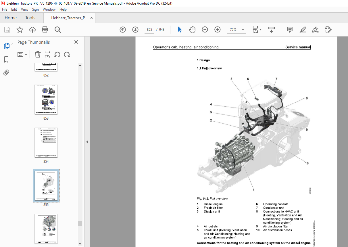
TABLE OF CONTENTS:
Liebherr Tractor PR 776-1296_05 G6.0 PR 776-1296_4F G6.0 Crawler dozer Service Manual – PDF DOWNLOAD
010.1 Safety instructions 010-4
0101.1 General safety instructions 010-4
010.1.2 Safety guidelines for crushing and burn prevention 010-5
010.1.3 Safety guidelines for fire and explosion prevention 010-5
010.14 Safety instructions for machine start up 010-6
0101.5 Safety guidelines for start up 010-6
010.1.6 Safety guidelines for working 010-6
0101.7 Safety guidelines for turning machine off 010-8
010.1.8 Safety instructions for transporting machine 010-8
010.1.9 Safety instructions for towing machine 010-8
010.1.10 Safety instructions for maintenance 010-9
010.1.11 Safety guidelines for welding work on machine 010-11
010.1.12 Safety guidelines for working on attachment 010-11
010.1.13 Safety guidelines for loading machine with a crane 010-12
8 010.2.1 Tools – Diesel engine 010-16
: 0102.2 Tools – Hydraulic system 010-18
2 010.2.3 Tools – Hydraulic cylinder 010-23
: 010.24 Tools – Electrical system 010-24
§ 010.2.5 Tools – Travel gearbox 010-27
5 0102.6 Tools – Undercarriage 010-28
0102.7 Tools – Oscillating axle frame 010-30
fine metric thread according to DIN ISO 261 010-33
010.3.1.1 Scope of application and purpose 010-33
010.3.1.2 Further applicable documentation 010-33
010.3.1.3 Changes and descriptions 010-34
010.3.1.4 Tightening values 010-34
62) 010-40
010.3.1.6 Half flange for low pressure (standard 61) 010-40
010.3.2 Installation specifications 010-41
010.3.2.1 Duo cone slipring seals 010-41
010.3.3 Tapping bores 010-43
010.3.3.1 Tapping bores of metric ISO standard threads 010-43
010.3.3.2 Tapping bores of metric ISO fine threads 010-45
010.3.4 Conversion tables 010-48
010.4 Conservation guidelines 010-49
010.4.1 General 010-49
010.4.2 Taking the machine out of service for an unknown duration 010-49
010.4.3 Shut down of the machine 010-50
0104.31 Shut down for up to 2 months 010-50
0104.3.2 Shut down for up to 12 months 010-51
0104.33 Shut down for longer than 12 months 010-52
010.4.4 Return to operation 010-52
010.4.4.1 After a shut down of 2 months 010-52
0104.4.2 After a shut down of 12 months 010-52
010.443 After shut down of longer than 12 months 010-53
010.5 Repair welding 010-54
010.5.1 Preparation of cracked part 010-54
010.5.1 Preparation of a weld 010-55
010.5.1 Treatment of electrodes 010-55
010.5.1 Welding technique 010-55
010.5.1 Reinforcement of welding seam 010-56
010.5.1 General use of reinforcement sheeting 010-56
010.5.1.1 Thickness of sheeting 010-56
010.5.1.1 Material quality of sheeting 010-57
010.5.1.1 Application of reinforcement sheeting 010-57
010.5.1.1 Welding the reinforcement sheeting 010-57
010.5.1.1 Selection of correct welding electrodes 010-58
010.5.1.2 Electrode selection 010-58
010.5.1.2 Steel chart 010-59
010.5.1.2 Welding additives chart 010-60
010.86 Hydraulic symbols 010-64
010.7 Electrical symbols 010-74
010.8 Material weights 010-78
020 Technical data 020-1
020.1 Overall machine 020-3
020.1.1 Complete machine – Overview
PR776-1296-05 G6.0/16877-; PR776-1296-4F G6.0/16877-; 020-3
020.2 Drive group 020-6
0202.1 Diesel engine
PR776-1296-05 G6.0/16877-; PR776-1296-4F G6.0/16877-; 020-6
020.2.2 Clutch
PR776-1296-05 G6.0/16877-; PR776-1296-4F G6.0/16877-; 020-7
020.2.3 Splitter box
PR776-1296-05 G6.0/16877-; PR776-1296-4F G6.0/16877-; 020-7
020.3 Cooling system 020-9
020.3.1 Regulator pump for coolant circuit
PR776-1296-05 G6.0/16877-; PR776-1296-4F G6.0/16877-; 020-9
020.3.2 Fan drive gear motors of hydraulic oil cooler
PR776-1296-05 G6.0/16877-; PR776-1296-4F G6.0/16877-; 020-9
& 020.3.3 Axial piston motor fan drive of water cooler and intercooler
g PR776-1296-05 G6.0/16877-; PR776-1296-4F G6.0/16877-; 020-9
g 020.4 Working hydraulics 020-10
8 0204.1 Working hydraulics regulating pump
8 PR776-1296-05 G6.0/16877-; PR776-1296-4F G6.0/16877-; 020-10
g
8 020.4.2 Front equipment, proportional control valve block
§ PR776-1296-05 G6.0/16877-; PR776-1296-4F G6.0/16877-; 020-10
5 0204.3 Lift cylinder
PR776-1296-05 G6.0/16877-; PR776-1296-4F G6.0/16877-; 020-10
020.44 Tilt cylinder
PR776-1296-05 G6.0/16877-; PR776-1296-4F G6.0/16877-; 020-11
020.5.1 Variable displacement pump
PR776-1296-05 G6.0/16877-; PR776-1296-4F G6.0/16877-; 020-12
020.5.2 Variable displacement motor
PR776-1296-05 G6.0/16877-; PR776-1296-4F G6.0/16877-; 020-12
020.5.3 Double gear pump replenishing and pilot control working hydraulic
PR776-1296-05 G6.0/16877-; PR776-1296-4F G6.0/16877-; 020-12
020.6 Hydraulic components 020-13
020.6.1 Hydraulic tank
PR776-1296-05 G6.0/16877-; PR776-1296-4F G6.0/16877-; 020-13
020.7 Electrical system 020-14
020.7.1 Batteries – Installation
PR776-1296-05 G6.0/16877-; PR776-1296-4F G6.0/16877-; 020-14
020.8 Travel gearbox 020-15
020.8.1 Travel gearbox
PR776-1296-05 G6.0/16877-; PR776-1296-4F G6.0/16877-; 020-15
020.8.2 Brake system
PR776-1296-05 G6.0/16877-; PR776-1296-4F G6.0/16877-; 020-16
020.9 Travel gear, axles, tyres, drive shafts 020-17
020.9.1 Travel gear frame
PR776-1296-05 G6.0/16877-; PR776-1296-4F G6.0/16877-; 020-17
020.9.2 Idler
PR776-1296-05 G6.0/16877-; PR776-1296-4F G6.0/16877-; 020-17
020.9.3 Tension unit
PR776-1296-05 G6.0/16877-; PR776-1296-4F G6.0/16877-; 020-17
020.9.4 Track roller
PR776-1296-05 G6.0/16877-; PR776-1296-4F G6.0/16877-; 020-17
020.9.5 Carrier roller (Optional)
PR776-1296-05 G6.0/16877-; PR776-1296-4F G6.0/16877-; 020-17
020.9.6 Track chain
PR776-1296-05 G6.0/16877-; PR776-1296-4F G6.0/16877-; 020-18
020.9.7 Sprocket
PR776-1296-05 G6.0/16877-; PR776-1296-4F G6.0/16877-; 020-18 ¢
020.10 Working attachment 020-20 g
wo
020.10.1 Semi U-blade 8
PR776-1296-05 G6.0/16877-; PR776-1296-4F G6.0/16877-; 020-20 3
020.10.2 Cutting angle adjustment for blade &
PR776-1296-05 G6.0/16877-; PR776-1296-4F G6.0/16877-; 020-21 3
020.10.3 Cutting angle adjustment cylinder g
PR776-1296-05 G6.0/16877-; PR776-1296-4F G6.0/16877-; 020-21 g
020.10.4 Rear equipment, proportional control valve block
PR776-1296-05 G6.0/16877-; PR776-1296-4F G6.0/16877-; 020-22
030 Maintenance 030-1
030.1 Maintenance and inspection schedule 030-9
030.2 Fill quantities, lubrication schedule 030-14
030.2.1 Recommended lubricants
PR776-1296-4F G6.0/16877-; 030-14
030.22 Recommended fuel and operating fluids
PR776-1296-4F G6.0/16877-; 030-15
030.2.3 Lubrication schedule
PR776-1296-05 G6.0; PR776-1296-4F G6.0; 030-15
030.3 Lubricants and fuels 030-18
030.3.1 General information about lubricants and fuels 030-18
030.3.1.1 General Information 030-18
030.3.1.2 General questions 030-18
030.3.1.3 Safety data sheets 030-18
030.3.1.4 Technical data sheets 030-18
030.3.1.5 Specific Liebherr standards 030-18
030.3.2 Diesel fuels
PR776-1296-4F G6.0/16877-; 030-19
030.3.2.1 Liebherr recommendation 030-19
030.3.3 Engine oils
PR776-1296-4F G6.0/16877-; 030-19
030.3.3.1 Liebherr recommendations for stage |V/tier 4f and
stage V diesel engines 030-19
030.3.3.2 Aggravating circumstances 030-20
030.3.4 Coolant
PR776-1296-4F G6.0/16877-; 030-21
030.3.4.1 Requirements for water used 030-21
£ 030.3.4.2 Anti-freeze and corrosion protection agent 030-21
g 030.3.4.2 Liebherr recommendation 030-21
g 030.3.42 Minimum quality requirement 030-21
: 030.3.5 Diesel exhaust fluids
g PR776-1296-4F G6.0/16877-; 030-21
§ 030.3.5.1 Liebherr recommendation 030-21
5 030.3.5.2 Minimum quality requirement 030-22
030.3.6 Hydraulic oils
PR776-1296-4F G6.0/16877-; 030-22
030.3.6.2 Minimum quality requirement 030-22
030.3.6.3 Oil analysis 030-23
030.3.6.4 Filter change 030-23
030.3.6.5 Oil change 030-23
030.3.7 Lube oils for splitterboxes
PR776-1296-05 G6.0; PR776-1296-4F G6.0; 030-24
030.3.7.1 Quality 030-24
030.3.7.2 Viscosity 030-24
030.3.8 Lube oils for travel gearbox
PR776-1296-4F G6.0/16877-; 030-25
030.3.8.1 Quality 030-25
030.3.8.2 Viscosity 030-25
030.3.8.3 Oil change 030-25
030.3.9 Qil for duo cone (slipring) seal Travel gear
PR776-1296-05 G6.0; PR776-1296-4F G6.0; 030-26
030.3.10 Grease and other lubricants
PR776-1296-05 G6.0/16877-; 030-26
030.3.11 Qil for hinges and joints
PR776-1296-05 G6.0; PR776-1296-4F G6.0; 030-28
030.3.12 OQil for axle bearing
PR776-1296-05 G6.0; PR776-1296-4F G6.0; 030-28
030.4 Maintenance tasks 030-29
030.4.1 Safety instructions for maintenance
PR776-1296-05 G6.0; PR776-1296-4F G6.0; 030-29
030.4.2 Maintenance – preparations 030-29
030.4.2.1 Maintenance position
PR776-1296-4F G6.0/16877-; 030-29
0304.2.2 Turn the electrical system off
PR776-1296-05 G6.0; PR776-1296-4F G6.0; 030-32
030.4.2.3 Lift the operator’s cab
PR776-1296-4F G6.0/16877-; 030-33
030.4.2.4 Lower the operator’s cab ‘
PR776-1296-4F G6.0/16877-; 030-36
030.4.3 Overall machine 030-38
maintenance and proper condition
030.4.3.2 Lubricating all lube points according to lubrication
030.4.3.4 Oil samples and oil analysis
030.4.3.5 Wet cleaning the machine
PR776-1296-05 G6.0/12589-; PR776-1296-4F
030.43.7 Taking the machine out of service
030.4.4.2 Changing engine oil
030.4.4.3 Changing lube oil filters
030.4.4.4 Checking and changing ribbed V-belt
030.4.4.6 Checking diesel engine configuration for leaks and
030.4.4.7 Check the intake and exhaust lines for mounting and
030.4.4.8 Check the electrical system of the Diesel engine
030.4.4.9 Changing oil separator filter cartridge
030.4.4.10 Checking and changing heater flange
brackets for tight seating
g 030.4.4.15 Notes for work on the fuel system
PR776-1296-4F G6.0/16877-; 030-55
g 030.4.4.16 Fuel preliminary filter: Drain the condensation
4 PR776-1296-4F G6.0/16877-; 030-55
o
ES 030.4.4.17 Fuel tank: Drain condensation and sediments
2 PR776-1296-4F G6.0/16877-; 030-56
5 030.4.4.18 Changing fuel pre-filter cartridge
= PR776-1296-4F G6.0/16877-; 030-57
030.4.4.19 Changing fuel fine filter
PR776-1296-4F G6.0/16877-; 030-59
0304.4.21 Venting fuel system
PR776-1296-4F G6.0/16877-; 030-62
030.4.4.23 Replacing the air filter
PR776-1296-4F G6.0/16877-; 030-64
030.4.4.24 Splitterbox: Check the oil level
PR776-1296-4F G6.0/16877-; 030-67
030.4.4.25 Splitterbox: Change the oil
PR776-1296-4F G6.0/16877-; 030-68
030.4.5 Cooling system 030-70
0304.51 Check the coolant level and refill
PR776-1296-4F G6.0/16877-; 030-70
030.4.5.2 Check the cooling system for contamination and
clean it
PR776-1296-4F G6.0/16877-; 030-72
030.4.5.3 Checking the cooling system
PR776-1296-4F G6.0/16877-; 030-74
0304.5.4 Check the antifreeze concentration in the coolant.
PR776-1296-4F G6.0/16877-; 030-77
0304.5.5 Changing coolant
PR776-1296-4F G6.0/16877-; 030-84
030.46 Travel hydraulics 030-85
030.4.6.1 Change the replenishing circuit filter
PR776-1296-4F G6.0/16877-; 030-85
030.4.7 Hydraulic components 030-89
0304.71 Checking the oil level in the hydraulic tank and
topping up oil
PR776-1296-4F G6.0/16877-; 030-89
0304.7.2 Clean the magnetic rod on the hydraulic tank
PR776-1296-4F G6.0/16877-; 030-92
0304.7.3 Checking the hydraulic system for function and leaks
PR776-1296-4F G6.0/16877-; 030-93
0304.7.4 Clean the oil cooler §
PR776-1296-4F G6.0/16877-; 030-94 3
a
030.4.7.5 Changing hydraulic oil g
PR776-1296-4F G6.0/16877-; 030-95 a
030.4.7.5 Filling with hydraulic oil 2
PR776-1296-4F G6.0/16877-; 030-95 &
8
030.4.7.6 Drain water and sediments in the hydraulic tank §
PR776-1296-4F G6.0/16877-; 030-98 5
030.4.7.7 Change the return filter insert N
PR776-1296-4F G6.0/16877-; 030-99
030.4.8 Electrical system 030-101
030.4.8.2 Check the batteries
PR776-1296-4F G6.0/16877-; 030-101
030.4.8.3 Change the light bulbs
PR776-1296-4F G6.0/16877-; 030-105
0304.9 Travel gearbox 030-105
030.4.9.1 Travel gearbox: checking the condition
PR776-1296-05 G6.0; PR776-1296-4F G6.0; 030-105
030.4.9.2 Check the oil level
PR776-1296-4F G6.0/16877-; 030-105
030.4.9.3 Changing the oil
PR776-1296-4F G6.0/16877-; 030-106
030.4.9.4 Check the oil level in the duo cone (slipring) area
PR776-1296-4F G6.0/16877-; 030-109
030.4.9.5 Change oil in brake chamber
PR776-1296-4F G6.0/16877-; 030-109
030.4.9.6 Change the oil in the duo cone (slip ring) area
PR776-1296-4F G6.0/16877-; 030-111
0304.10 Travel gear, axles, tyres, drive shafts 030-116
components are firmly seated
PR776-1296-4F G6.0/16877-; 030-116
idlers and track carriers for leaks
030.4.10.3 Checking and adjusting the track tension
PR776-1296-4F G6.0/16877-; 030-118
030.4.104 Change the track
PR776-1296-4F G6.0/16877-; 030-122
030.4.10.5 Checking travel gear guides
PR776-1296-4F G6.0/16877-; 030-125
030.4.10.6 Checking the oil fill of the axle bearings
. PR776-1296-4F G6.0/16877-; 030-128
5 030.4.10.7 Check the rubber stop of the equalizer bar
g PR776-1296-4F G6.0/16877-; 030-129
g 030.4.10.8 Check the oil level of the track carriers
by PR776-1296-4F G6.0/16877-; 030-129
g 030.4.10.9 Checking the chain guides for wear
E] PR776-1296-4F G6.0/16877-; 030-131
g 030.4.10.10 Checking idler spacing and adjusting it, if necessary
5 PR776-1296-4F G6.0/16877-; 030-132
030.4.11 Working attachment 030-134
for wear
PR776-1296-05 G6.0/12589-; PR776-1296-4F
G6.0/12589-; 030-134
bearing
PR776-1296-4F G6.0/16877-; 030-135
play and wear
PR776-1296-4F G6.0/16877-; 030-135
the working attachment for tight seating
PR776-1296-4F G6.0/16877-; 030-139
030.4.12 Operator’s cab, heating, air conditioning 030-142
PR776-1296-4F G6.0/16877-; 030-142
circulation filter
PR776-1296-4F G6.0/16877-; 030-143
specialist staff
0304.124 Check the compressor mounting
PR776-1296-4F G6.0/16877-; 030-146
PR776-1296-05 G6.0/12589-; PR776-1296-4F
030.5 Testing and adjustment checklist
030.5.1 Adjustment checklist 030-147
030.5.2 Track Components Check List 030-159
030.5.2.1 Test report 030-159
PR776-1296-05 G6.0/16877-; PR776-1296-4
PR776-1296-05 G6.0/16877-; PR776-1296-4F
G6.0/16877-; 030-171
PR776-1296-05 G6.0/16877-; PR776-1296-4F
G6.0/16877~ 030-172
operating temperature:
PR776-1296-05 G6.0/16877-; PR776-1296-4F
G6.0/16877-; 030-172
mining adjustment range
PR776-1296-05 G6.0/16877-; PR776-1296-4F
G6.0/16877~ 030-173
PR776-1296-05 G6.0/16877-; PR776-1296-4F
030.6.4.2 Checking pressure relief valve — fan motor and fan
control
PR776-1296-05 G6.0/16877-; PR776-1296-4F
G6.0/16877-; 030-179
0306.5 Working hydraulics 030-185
PR776-1296-05 G6.0/16877-; PR776-1296-4F
G6.0/16877~ 030-185
control valve block
PR776-1296-05 G6.0/16877-; PR776-1296-4F
G6.0/16877-; 030-186
control valve block
PR776-1296-05 G6.0/16877-; PR776-1296-4F
G6.0/16877-; 030-187
PR776-1296-05 G6.0/16877-; PR776-1296-4F
G6.0/16877~; 030-189
PR776-1296-05 G6.0/16877-; PR776-1296-4F
G6.0/16877-; 030-191
PR776-1296-05 G6.0/16877-; PR776-1296-4F
G6.0/16877~ 030-192
pump
PR776-1296-05 G6.0/16877-; PR776-1296-4F
G6.0/16877-; 030-192
high pressure
PR776-1296-05 G6.0/16877-; PR776-1296-4F
G6.0/16877~; 030-193
PR776-1296-05 G6.0/16877-; PR776-1296-4F
G6.0/16877~; 030-196
PR776-1296-05 G6.0/16877-; PR776-1296-4F
G6.0/16877-; 030-207
PR776-1296-05 G6.0/16877-; PR776-1296-4F
G6.0/16877-; 030-220
PR776-1296-05 G6.0/16877-; PR776-1296-4F
G6.0/16877-; 030-227
PR776-1296-05 G6.0/16877-; PR776-1296-4F
G6.0/16877- 030-231
PR776-1296-05 G6.0/16877-; PR776-1296-4F
G6.0/16877- 030-233
PR776-1296-05 G6.0/16877-; PR776-1296-4F
040.1.1 Diesel engine — Full overview
PR776-1296-05 G6.0/16877-; PR776-1296-4F
G6.0/16877-; 040-9
PR776-1296-05 G6.0/16877-; PR776-1296-4F
G6.0/16877-; 040-12
PR776-1296-05 G6.0/16877-; PR776-1296-4F
G6.0/16877-; 040-13
PR776-1296-05 G6.0/16877-; PR776-1296-4F
G6.0/16877- 040-14
PR776-1296-05 G6.0/16877-; PR776-1296-4F
G6.0/16877~; 040-16
PR776-1296-05 G6.0/16877-; PR776-1296-4F
G6.0/16877~ 040-18
PR776-1296-05 G6.0/16877-; PR776-1296-4F
G6.0/16877~ 040-19
PR776-1296-05 G6.0/16877-; PR776-1296-4F
0401.5 Diesel engine mounting
PR776-1296-05 G6.0/16877-; PR776-1296-4F G6.0/16877-; 040-27
040.2 Clutch
PR776-1296-05 G6.0/16877-; PR776-1296-4F G6.0/16877-; 040-28
040.3 Splitter box
PR776-1296-05 G6.0/16877-; PR776-1296-4F G6.0/16877~ 040-30
050 Cooling system 050-1
050.1 Complete cooling system
PR776-1296-05 G6.0/16877-; PR776-1296-4F G6.0/16877- 050-2
050.2 Cooler arrangement 050-5
0502.1 Combi cooler
PR776-1296-05 G6.0/16877-; PR776-1296-4F G6.0/16877-; 050-5
050.3 Hydraulic 050-14
050.3.1 Gear motor – fan oil cooler
PR776-1296-05 G6.0/16877-; PR776-1296-4F G6.0/16877-; 050-14
5 050.3.2 Axial piston fixed displ. motor – fan drive
g PR776-1296-05 G6.0/16877-; PR776-1296-4F G6.0/16877-; 050-15
2
ww!
g 060 Working hydraulics 060-1
§ 060.1 Working hydraulics – Full overview
g PR776-1296-05 G6.0/16877-; PR776-1296-4F G6.0/16877- 060-2
g 060.2 Regulating pump 060-15
5 060.2.1 Regulating pump – full overview
PR776-1296-05 G6.0/16877-; PR776-1296-4F G6.0/16877-; 060-15
060.3 Proportional control valve block 060-20
PR776-1296-05 G6.0/16877-; PR776-1296-4F G6.0/16877-; 060-21
060.4 Pilot control Working hydraulic 060-24
060.4.1 Pilot control Full overview
PR776-1296-05 G6.0/16877-; PR776-1296-4F G6.0/16877-; 060-24
0680.5 Hydraulic cylinder 060-30
060.5.1 Lift cylinder
PR776-1296-05 G6.0/16877-; PR776-1296-4F G6.0/16877-; 060-30
060.5.2 Tilt cylinder
PR776-1296-05 G6.0/16877-; PR776-1296-4F G6.0/16877-; 060-31
070 Travel hydraulics 070-1
070.1 Complete travel hydraulics
PR776-1296-05 G6.0/16877-; PR776-1296-4F G6.0/16877-; 070-2
070.2 Regulating pump
PR776-1296-05 G6.0/16877-; PR776-1296-4F G6.0/16877-; 070-15
070.3 Variable displacement pump
PR776-1296-05 G6.0/16877-; PR776-1296-4F G6.0/16877-; 070-19
070.4 Variable displacement motors 070-28
070.4.1 Variable displacement motors – Full overview
PR776-1296-05 G6.0/16877-; PR776-1296-4F G6.0/16877-; 070-28
070.5 Distributor block 070-37
070.5.1 Distributor blocks
PR776-1296-05 G6.0/16877-; PR776-1296-4F G6.0/16877-; 070-37
080 Hydraulic components 080-1
080.1 Hydraulic cylinder 080-2
080.1.1 Ripper cylinder
PR776-1296-05 G6.0/16877-; PR776-1296-4F G6.0/16877-; 080-2
080.1.2 Valves
PR776-1296-05 G6.0/16877-; PR776-1296-4F G6.0/16877-; 080-3
080.2 Hydraulic tank 080-16 £
080.2.1 Hydraulic tank 5)
PR776-1296-05 G6.0/16877-; PR776-1296-4F G6.0/16877-; 080-16 2
080.22 Return filter by
PR776-1296-05 G6.0/16877-; PR776-1296-4F G6.0/16877-; 080-20 g
100 Brake system 100-1 :
100.1 Inching brake pedal 100-2 –
PR776-1296-05 G6.0/16877-; PR776-1296-4F G6.0/16877-; 100-2
110.1 Electrical system – Full overview
PR776-1296-05 G6.0/16877-; PR776-1296-4F G6.0/16877-; 110-3
110.2 Lighting system
PR776-1296-05 G6.0/16877-; PR776-1296-4F G6.0/16877-; 110-6
110.3 Circuit diagrams
PR776-1296-05 G6.0/16877-; PR776-1296-4F G6.0/16877-; 110-10
110.4 Electrical components in operator’s cab
PR776-1296-05 G6.0/16877-; PR776-1296-4F G6.0/16877-; 110-11
110.4.2 Central control – Master (A100)
PR776-1296-05 G6.0/16877-; PR776-1296-4F G6.0/16877-; 110-18
110.4.3 Travel sensor
PR776-1296-05 G6.0/16877-; PR776-1296-4F G6.0/16877-; 110-24
110.4.4 Speed control
PR776-1296-05 G6.0/16877-; PR776-1296-4F G6.0/16877-; 110-26
110.5 Electrical components – Heatable exterior mirror (option)
PR776-1296-05 G6.0/16877-; PR776-1296-4F G6.0/16877-; 110-28
110.6 Electrical components – Diesel engine
PR776-1296-05 G6.0/16877-; PR776-1296-4F G6.0/16877-; 110-29
110.7 Electrical components – Main frame
PR776-1296-05 G6.0/16877-; PR776-1296-4F G6.0/16877-; 110-36
110.8 Electrical components Compartments 110-43
110.8.1 Battery compartment
PR776-1296-05 G6.0/16877-; PR776-1296-4F G6.0/16877-; 110-43
110.8.2 Fuel tank
PR776-1296-05 G6.0/16877-; PR776-1296-4F G6.0/16877-; 110-43
110.8.3 Diesel exhaust fluid system container
PR776-1296-05 G6.0/16877-; PR776-1296-4F G6.0/16877-; 110-44
110.8.4 Central electrical system compartment
PR776-1296-05 G6.0/16877-; PR776-1296-4F G6.0/16877-; 110-47
110.8.5 Hydraulic tank
PR776-1296-05 G6.0/16877-; PR776-1296-4F G6.0/16877-; 110-53
110.9 Display unit
§ PR776-1296-05 G6.0/16877-; PR776-1296-4F G6.0/16877-; 110-54
§ 110.10 Electrical components LiDAT (option)
g PR776-1296-05 G6.0/16877-; PR776-1296-4F G6.0/16877-; 110-55
H 110.11 Electrical components LiTU3 (option)
5 PR776-1296-05 G6.0/16877-; PR776-1296-4F G6.0/16877-; 110-56
g 110.12 Electrical components – Incline alarm (option)
g PR776-1296-05 G6.0/16877-; PR776-1296-4F G6.0/16877-; 110-57
g 110.13 Electrical components – Data interface (option)
PR776-1296-05 G6.0/16877-; PR776-1296-4F G6.0/16877-; 110-60
110.14 Electrical components – Input module A240 (option)
PR776-1296-05 G6.0/16877-; PR776-1296-4F G6.0/16877-; 110-63
110.16 Electrical components – Travel hydraulics pressure cut-off
PR776-1296-05 G6.0/16877-; PR776-1296-4F G6.0/16877-; 110-67
110.17 Electrical components – Acoustic reversing warning device (option)
PR776-1296-05 G6.0/16877-; PR776-1296-4F G6.0/16877-; 110-68
110.18 Electrical components – Disengageable reversing warning device (option)
PR776-1296-05 G6.0/16877-; PR776-1296-4F G6.0/16877-; 110-70
110.19 Electrical components – Optical reversing warning device (option)
PR776-1296-05 G6.0/16877-; PR776-1296-4F G6.0/16877-; 110-73
110.20 Electrical components – Engine after-run
PR776-1296-05 G6.0/16877-; PR776-1296-4F G6.0/16877-; 110-76
110.21 Electrical components – Access ladder
PR776-1296-05 G6.0/16877-; PR776-1296-4F G6.0/16877-; 110-77
110.22 Electrical components – Warm water heating device (option)
PR776-1296-05 G6.0/16877-; PR776-1296-4F G6.0/16877-; 110-80
110.23 Electrical components – Jump-start (option)
PR776-1296-05 G6.0/16877-; PR776-1296-4F G6.0/16877-; 110-85
110.24 Electrical components – Reversible fan drive (option)
PR776-1296-05 G6.0/16877-; PR776-1296-4F G6.0/16877-; 110-86
110.25 Electrical components – Working hydraulics cutting angle adjustment (option)
PR776-1296-05 G6.0/16877-; PR776-1296-4F G6.0/16877-; 110-88
110.26 Electrical components – 3-point belt with warning sound (option)
PR776-1296-05 G6.0/16877-; PR776-1296-4F G6.0/16877-; 110-91
110.27 Electrical components – Supply box for external users (option)
PR776-1296-05 G6.0/16877-; PR776-1296-4F G6.0/16877-; 110-94
110.28 Electrical components – Coolant level check (option)
PR776-1296-05 G6.0/16877-; PR776-1296-4F G6.0/16877-; 110-97
110.29 Electrical components – External operating hour meter (option)
PR776-1296-05 G6.0/16877-; PR776-1296-4F G6.0/16877-; 110-99
110.30 Electrical components – Generator disconnecting switch (option)
PR776-1296-05 G6.0/16877-; PR776-1296-4F G6.0/16877-; 110-100
110.31 Electrical components – Ripper headlight (option)
PR776-1296-05 G6.0/16877-; PR776-1296-4F G6.0/16877-; 110-102
120 Travel gearbox 120-1 g
120.1 Travel gear, overall 3
PR776-1296-05 G6.0/16877-; PR776-1296-4F G6.0/16877-; 120-2 J
o
120.2 Brake system g
PR776-1296-05 G6.0/16877-; PR776-1296-4F G6.0/16877-; 120-7 g
120.3 Duo cone slipring seal 3
PR776-1296-05 G6.0/16877-; PR776-1296-4F G6.0/16877-; 120-9
PR776-1296-05 G6.0/16877-; PR776-1296-4F G6.0/16877-; 120-10
130.1 Travel gear frame 130-2
130.1.1 Support frame
PR776-1296-05 G6.0/16877-; PR776-1296-4F G6.0/16877-; 130-2
130.2 Idler
PR776-1296-05 G6.0/16877-; PR776-1296-4F G6.0/16877- 130-3
130.3 Tension unit
PR776-1296-05 G6.0/16877-; PR776-1296-4F G6.0/16877-; 130-4
130.4 Track roller
PR776-1296-05 G6.0/16877-; PR776-1296-4F G6.0/16877-; 130-5
130.5 Carrier roller (Optional)
PR776-1296-05 G6.0/16877-; PR776-1296-4F G6.0/16877- 130-6
130.6 Function, wear and evaluation
PR776-1296-05 G6.0; PR776-1296-4F G6.0; 130-7
140 Steel components Basic machine 140-1
140.1 Lift cylinder suspension
PR776-1296-05 G6.0/16877-; PR776-1296-4F G6.0/16877-; 140-2
140.2 Oscillating axle frame
PR776-1296-05 G6.0/16877-; PR776-1296-4F G6.0/16877-; 140-3
140.3 Push frame
PR776-1296-05 G6.0/16877-; PR776-1296-4F G6.0/16877-; 140-5
150 Working attachment 150-1
150.1 Semi U-blade
PR776-1296-05 G6.0/16877-; PR776-1296-4F G6.0/16877- 150-2
160.2 Hydraulic cutting angle adjustment
PR776-1296-05 G6.0/16877-; PR776-1296-4F G6.0/16877-; 150-4
160.3 Ripper
PR776-1296-05 G6.0; PR776-1296-4F G6.0; 150-15
160.3.1 Ripper proportional control valve block – Full overview
PR776-1296-05 G6.0/16877-; PR776-1296-4F G6.0/16877-; 150-15
5 150.4 Cutting angle adjustment – Ripper
£ PR776-1296-05 G6.0/16877-; PR776-1296-4F G6.0/16877~ 150-18
g 160 Operator’s cab, heating, air conditioning 160-1
& 160.1 Operator’s platform 160-2
8 160.1.1 Operator’s platform installations
§ PR776-1296-05 G6.0/16877-; PR776-1296-4F G6.0/16877-; 160-2
5 160.1.2 Operator’s platform bearing
PR776-1296-05 G6.0/16877-; PR776-1296-4F G6.0/16877-; 160-3
160.1.3 Support cylinder
PR776-1296-05 G6.0/16877-; PR776-1296-4F G6.0/16877-; 160-6
PR776-1296_05 G6.0 LIEBHERR 23
Contents Service manual
160.2.1 Operator’s seat
PR776-1296-05 G6.0/16877-; PR776-1296-4F G6.0/16877-; 160-10
160.2.2 Assembly of third party installations in the cab
PR776-1296-05 G6.0/16877-; PR776-1296-4F G6.0/16877-; 160-10
160.3 Heater and ventilation 160-13
160.3.1 Warm water heater 160-13
160.3.1.1 Hose routing for warm water heating device
PR776-1296-05 G6.0/16877-; PR776-1296-4F
G6.0/16877-; 160-13
160.4 Heating, ventilation, air conditioning 160-15
160.4.1 Heating and air conditioning system 160-15
PR776-1296-05 G6.0/16877-; PR776-1296-4F
190.1 Reversible fan drive
VIDEO PREVIEW OF THE MANUAL:
PLEASE NOTE:
- This is the SAME manual used by the dealers to troubleshoot any faults in your vehicle. This can be yours in 2 minutes after the payment is made.
- Contact us at [email protected] should you have any queries before your purchase or that you need any other service / repair / parts operators manual.
S.V


