

Liebherr Tractor PR 776 1296 Crawler dozer Service Manual – PDF DOWNLOAD
FILE DETAILS:
Liebherr Tractor PR 776 1296 Crawler dozer Service Manual – PDF DOWNLOAD
Language : English
Pages : 997
Downloadable : Yes
File Type : PDF
Size: 224 MB
DESCRIPTION:
Liebherr Tractor PR 776 1296 Crawler dozer Service Manual – PDF DOWNLOAD
This Service manual is intended for trained specialist staff in the Liebherr organization and its dealers.
The Service manual provides specific knowledge for the maintenance of Liebherr construction machinery. Basic technical knowledge of electrics, hydraulics, mechanics and Diesel engine technology are not detailed in this Service manual. A subject-based, qualified training is therefore necessary. Liebherr recommends participation on the Liebherr Training program for construction machinery.
In this Service manual you find information about:
For information relating to control and operation refer to the operator’s manual. For information relating to spare parts refer to the Spare parts catalog. Observe the locally applicable accident prevention regulations.
- Familiarize yourself with the operator’s manual before putting the machine into service. Also, ensure you have obtained, read, and understood any additional instructions regarding special accessories for the machine.
- Only authorized personnel may operate, maintain, or repair the machine. Remember to observe the minimum legal age limit.
- Utilize trained or instructed personnel and clearly define their responsibilities for operation, setup, maintenance, and repairs.
- Determine the machine operator’s responsibility, including adherence to traffic regulations, and empower them to refuse unsafe instructions from third parties.
- Do not allow untrained or trainee individuals to operate or work on the machine without constant supervision and guidance from an experienced instructor or operator.
- Periodically check and observe anyone operating or working on the machine to ensure they follow the safety instructions and guidelines provided in the operator’s manual.
- Always wear appropriate work clothing when operating or working on the machine. Avoid wearing rings, watches, ties, scarves, open jackets, or loose clothing that may pose a risk of injury by getting stuck or pulled in. Use prescribed safety equipment for specific tasks, such as safety glasses, safety shoes, safety helmets, work gloves, reflective vests, and ear protection.
- Consult the supervisor at the jobsite for special safety instructions and regulations.
- Maintain three-point contact when entering and exiting the machine.
- Never use joysticks as handholds when entering or exiting the machine to prevent inadvertent movement and serious accidents.
- Avoid jumping off the machine. Use designated steps, ladders, catwalks, and handles when climbing on or off the machine. Use both hands for support and face the machine.
- Keep steps, ladders, and handles free of oil, grease, mud, snow, and ice to minimize the risk of slipping, stumbling, or falling.
- Familiarize yourself with the emergency exit.
- If no other instructions are provided, follow this procedure for maintenance and repair work:
- Park the machine on solid and level ground.
- Bring all control levers to the neutral position.
- Set the parking switch to the park position.
- Turn off the engine and remove the ignition key.
- Actuate the control levers several times to relieve pressure in the servo lines.
- Bring all control levers to the neutral position.
- Before working on the hydraulic circuit, with the engine turned off and the ignition key in the contact position, move all pilot controls (joysticks and pedals) in both directions to relieve servo pressure and remaining back pressures in the working circuits. Then release the internal hydraulic tank pressure.
- Before leaving the operator’s seat, switch the parking switch to the park position.
- Secure all loose parts on the machine.
- Never operate the machine without conducting a complete walk-around inspection. Check if all warning signs are present on the machine and if they are legible.
- Observe all signs indicating danger and safety instructions.
IMAGES PREVIEW OF THE MANUAL:
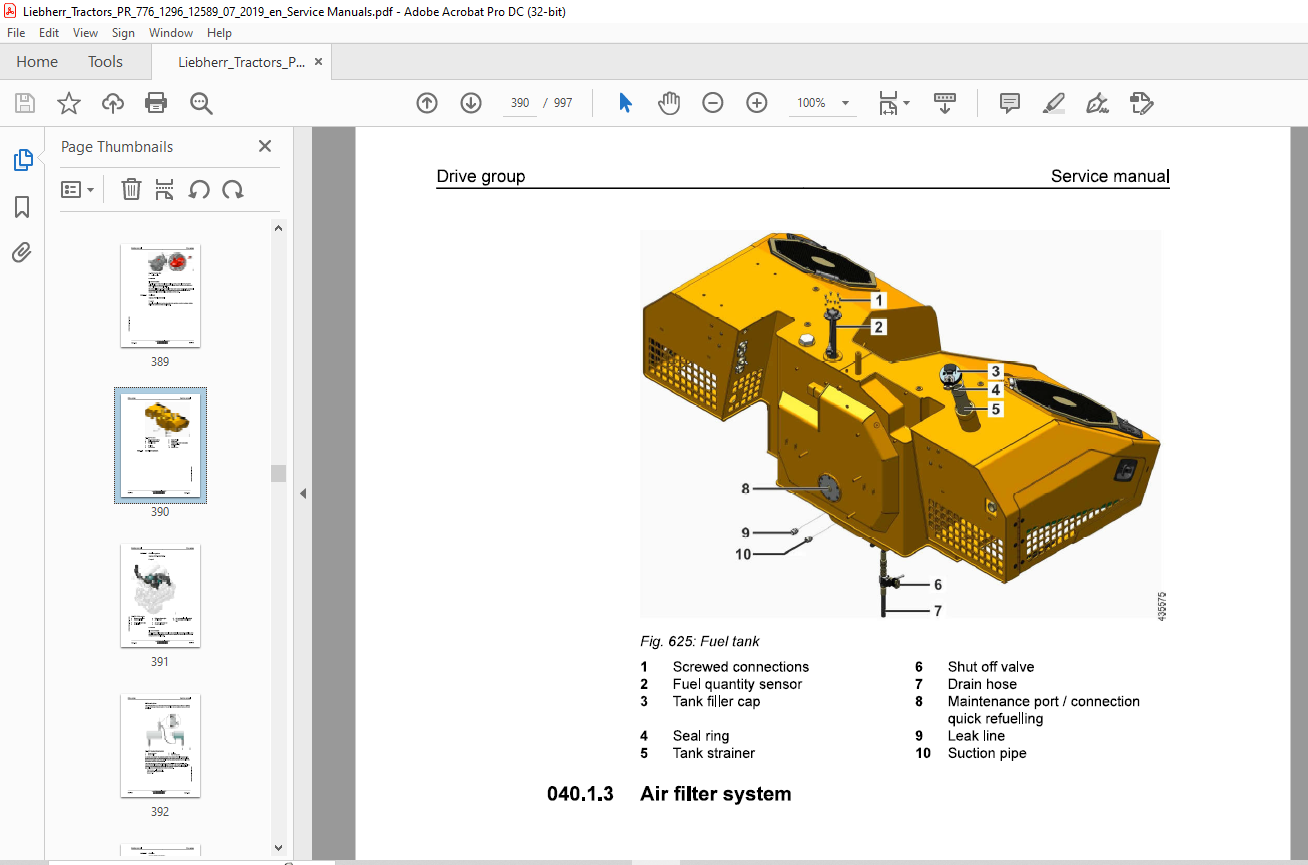
TABLE OF CONTENTS:
Liebherr Tractor PR 776 1296 Crawler dozer Service Manual – PDF DOWNLOAD
010.1 Safety instructions 010-4
0101.1 General safety instructions 010-4
010.1.2 Safety guidelines for crushing and burn prevention 010-5
010.1.3 Safety guidelines for fire and explosion prevention 010-5
010.14 Safety instructions for machine start up 010-6
0101.5 Safety guidelines for start up 010-6
010.1.6 Safety guidelines for working 010-6
0101.7 Safety guidelines for turning machine off 010-8
010.1.8 Safety instructions for transporting machine 010-8
010.1.9 Safety instructions for towing machine 010-8
010.1.10 Safety instructions for maintenance 010-9
010.1.11 Safety guidelines for welding work on machine 010-11
010.1.12 Safety guidelines for working on attachment 010-11
010.1.13 Safety guidelines for loading machine with a crane 010-12
010.1.14 Safety notes for maintenance of hydraulic hoses and hose lines 010-12
accumulators 010-13
010.1.16 Equipment and attachment parts 010-13
010.1.17 Protection from vibrations 010-13
010.1.18 See and be seen 010-14
010.1.18.2 Field of vision 010-15
010.1.18.3 Measures before and during operation 010-16
010.1.19 Safety notes for Diesel engines with electronic control units 010-16
010.2 Special tools for maintenance and repair work 010-18
010.2.1 Tools – Diesel engine 010-18
010.2.2 Tools – Hydraulic system 010-20
0102.3 Tools – Hydraulic cylinder 010-25
010.24 Tools – Electrical system 010-26
0102.5 Tools – Travel gearbox 010-28
010.2.7 Tools – Oscillating axle frame 010-31
010.2.8 Tools, operator’s platform 010-32
Standards and specifications 010-34
010.3.1 Preload values and tightening torques for screws with standard and
fine metric thread according to DIN ISO 261 010-34
010.3.1.1 Scope of application and purpose 010-34
010.3.1.2 Further applicable documentation 010-34
010.3.1.3 Changes and descriptions 010-35
010.3.1.4 Tightening values 010-35
010.3.1.5 Flanges and half flanges for high pressure (standard
62) 010-41
010.3.1.6 Half flange for low pressure (standard 61) 010-41
010.3.1.7 Tightening torques for cutting edges, end bits and
adapters 010-41
010.3.2 Installation specifications 010-42
010.3.2.1 Duo cone slipring seals 010-42
010.3.3 Tapping bores 010-44
010.3.3.1 Tapping bores of metric ISO standard threads 010-44
010.3.3.2 Tapping bores of metric ISO fine threads 010-46
010.3.4 Conversion tables 010-49
Conservation guidelines 010-50
0104.1 General 010-50
010.4.2 Taking the machine out of service for an unknown duration 010-50
010.4.3 Shut down of the machine 010-51
010.4.3.1 Shut down for up to 2 months 010-51
0104.3.2 Shut down for up to 12 months 010-52
010.4.33 Shut down for longer than 12 months 010-53
010.44 Return to operation 010-53
010.4.4.1 After a shut down of 2 months 010-53
010.4.4.2 After a shut down of 12 months 010-53
0104.43 After shut down of longer than 12 months 010-54
Repair welding 010-55
010.5.1 Preparation of cracked part 010-55
010.5.1 Preparation of a weld 010-56
010.5.1 Treatment of electrodes 010-56
010.5.1 Reinforcement of welding seam 010-57
010.5.1 General use of reinforcement sheeting 010-57
010.5.1.1 Form of sheeting 010-57
010.5.1.1 Thickness of sheeting 010-57
010.5.1.1 Material quality of sheeting 010-58
010.5.1.1 Application of reinforcement sheeting 010-58
010.5.1.1 Welding the reinforcement sheeting 010-58
010.5.1.1 Selection of correct welding electrodes 010-59
010.5.1.2 Electrode selection 010-59
010.5.1.2 Steel chart 010-60
010.5.1.2 Welding additives chart 010-61
010.6 Hydraulic symbols 010-65
010.7 Electrical symbols 010-75
010.8 Material weights 010-79
020 Technical data 020-1
020.1 Overall machine 020-3
020.1.1 Complete machine – Overview
PR776-1296/12589-; 020-3
020.2 Drive group 020-6
020.2.1 Diesel engine
PR776-1296/12589-; 020-6
020.2.2 Clutch
PR776-1296/12589-; 020-7
020.2.3 Splitter box
PR776-1296/12589-; 020-7
020.3 Cooling system 020-9
020.3.1 Regulator pump for coolant circuit
PR776-1296/12589-; 020-9
020.3.2 Fan drive gear motors of hydraulic oil cooler
PR776-1296/12589-; 020-9
020.3.3 Axial piston motor fan drive of water and charge air cooler
PR776-1296/12589-; 020-9
020.4 Working hydraulics 020-10
0204.1 Working hydraulics regulating pump
PR776-1296/12589-; 020-10
020.4.2 Front equipment, proportional control valve block
PR776-1296/12589-; 020-10
020.4.3 Lift cylinder
PR776-1296/12589-; 020-10
020.4.4 Tilt cylinder
PR776-1296/12589-; 020-11
020.5 Travel hydraulics 020-12
020.5.1 Variable displacement pump
PR776-1296/12589-; 020-12
020.5.2 Variable displacement motor
PR776-1296/12589-; 020-12
020.5.3 Double gear pump replenishing and pilot control working hydraulic
PR776-1296/12589-; 020-12
020.6 Hydraulic components 020-13
020.6.1 Hydraulic tank
PR776-1296/12589-; 020-13
020.7 Electrical system 020-14
020.7.1 Batteries – Installation
PR776-1296/12589-; 020-14
020.8 Travel gearbox 020-15
020.8.1 Travel gearbox
PR776-1296/12589-; 020-15
020.8.2 Brake system
PR776-1296; 020-16
020.9 Travel gear, axles, tyres, drive shafts 020-17
020.9.1 Travel gear frame
PR776-1296/12589-; 020-17
020.9.2 Idler
PR776-1296/12589-; 020-17
020.9.3 Tension unit
PR776-1296/12589-; 020-17
020.9.4 Track roller
PR776-1296/12589-; 020-17
020.9.5 Carrier roller (Optional)
PR776-1296/12589-; 020-17
020.9.6 Track chain
PR776-1296/12589-; 020-18
020.9.7 Sprocket
PR776-1296/12589-; 020-18
020.10 Working attachment 020-20
020.10.1 Semi U-blade
PR776-1296/12589-; 020-20
020.10.2 Cutting angle adjustment for blade
PR776-1296/12589-; 020-21
PR776-1296/12589-; 020-21
020.10.4 Rear equipment, proportional control valve block
PR776-1296/12589-; 020-22
020.10.5 Ripper with cutting angle adjustment
PR776-1296/12589-; 020-22
030 Maintenance 030-1
030.1 Maintenance and inspection schedule 030-8
030.2 Fill quantities, lubrication schedule 030-13
030.2.1 Recommended lubricants
PR776-1296/12589-; 030-13
030.22 Recommended fuel and operating fluids
PR776-1296/12589-; 030-14
0302.3 Lubrication schedule
PR776-1296; 030-14
030.3 Lubricants and fuels 030-17
030.3.1 General information about lubricants and fuels 030-17
030.3.1.1 General Information 030-17
030.3.1.2 General questions 030-17
030.3.1.3 Safety data sheets 030-17
030.3.1.4 Technical data sheets 030-17
030.3.1.5 Specific Liebherr standards 030-17
030.3.2 Diesel fuels
PR776-1296/12589-; 030-18
030.3.2.1 Specification 030-18
030.3.2.2 Sulfur content in Diesel fuel 030-18
030.3.2.3 Diesel fuel – Lubricity 030-18
030.3.2.4 Ignitability 030-18
030.3.2.5 Diesel fuels at low temperatures (winter operation) 030-18
030.3.3 Lubricating oils for Diesel engines
PR776-1296/12589-; 030-19
030.3.3.1 Lube oil quality 030-19
030.3.3.2 Lube oil viscosity 030-19
030.3.3.3 Lube oil change intervals 030-20
030.34 Coolant for Diesel engines
PR776-1296/12589-; 030-20
030.3.4.1 General recommendations 030-20
030.34.2 Water (Fresh water) 030-21
030.3.4.3 Coolant mixing ratio 030-21
030.3.4.4 Approved anti-freeze and corrosion protection agent 030-22
030.3.4.5 Approved premixed anti-freeze and corrosion protec-
tion agent 030-22
030.3.4.6 Approved corrosion inhibitors without antifreeze
protection 030-23
030.3.5 Hydraulic oil
PR776-1296; 030-23
030.3.5.1 Liebherr Hydraulic oil 030-23
030.3.5.2 Engine oil as hydraulic oil 030-24
030.3.5.3 Warm up specification 030-25
030.3.5.4 Biodegradable hydraulic oils 030-25
030.3.5.5 Oil change, oil analysis, filter change 030-26
030.3.6 Lube oils for splitterboxes
PR776-1296; 030-28
030.3.6.1 Quality 030-28
030.3.6.2 Viscosity 030-29
030.3.7 Lube oils for travel gearbox
PR776-1296/12589-; 030-29
030.3.7.1 Quality 030-29
030.3.7.2 Viscosity 030-30
030.3.7.3 Oil change 030-30
030.3.8 Qil for duo cone (slipring) seal Travel gear
PR776-1296; 030-31
030.3.9 Grease and other lubricants
PR776-1296/12589-; 030-31
030.3.10 Qil for hinges and joints
PR776-1296; 030-32
030.3.11 Qi for axle bearing
PR776-1296; 030-33
030.4 Maintenance tasks 030-34
030.4.1 Safety instructions for maintenance
PR776-1296; 030-34
030.4.2 Maintenance – preparations 030-34
0304.21 Maintenance position
PR776-1296/12589-; 030-34
030.4.2.2 Turn the electrical system off
PR776-1296; 030-37
030.4.2.3 Lift the operator’s cab
PR776-1296/12589-; 030-37
Overall machine 030-42
030.4.3.1 Checking the machine for external damage, correct
030.4.3.2 Lubricating all lube points according to lubrication
030.4.3.3 Checking the window wiper
030.4.3.4 Check the hose clamp with spring pretension
030.4.3.5 Oil samples and oil analysis
030.4.3.6 Wet cleaning the machine
030.4.3.7 Protect the piston rods
030.4.3.8 Taking the machine out of service
Drive group 030-51
030.4.4.1 Checking the engine oil level
030.4.4.2 Changing the engine oil
030.4.4.3 Changing lube oil filters
030.4.4.4 Checking the diesel engine configuration and the
030.4.4.5 Checking and changing ribbed V-belt
030.44.6 Check the Diesel engine arrangement for leaks and
030.4.4.7 Check the intake and exhaust lines for mounting and
030.4.4.8 Check the electrical system of the Diesel engine
030.4.4.9 Changing oil separator filter cartridge
030.4.4.10 Checking and changing heater flange
030.4.4.13 Fuel preliminary filter: Drain the condensation
PR776-1296/12589-; 030-61
030.4.4.14 Fuel tank: Drain condensation and sediments
PR776-1296/12589-; 030-62
0304.4.15 Changing fuel pre-filter cartridge
PR776-1296/12589-; 030-63
030.4.4.16 Changing fuel fine filter
PR776-1296/12589-; 030-65
030.4.4.17 Empty and clean the fuel tank
PR776-1296/12589-; 030-66
030.4.4.18 Venting fuel system
PR776-1296/12589-; 030-68
030.4.4.20 Replacing the air filter
PR776-1296/12589-; 030-70
030.4.4.21 Splitterbox: Check the oil level
PR776-1296/12589-; 030-73
030.4.4.22 Splitterbox: Change the oil
PR776-1296/12589-; 030-74
030.4.5 Cooling system 030-76
030.4.5.1 Check the coolant level and refill
PR776-1296/12589-; 030-76
0304.5.2 Check the cooling system for contamination and
clean it
PR776-1296/12589-; 030-78
0304.53 Checking the cooling system
PR776-1296/12589-; 030-80
030.4.5.4 Check the antifreeze concentration in the coolant.
PR776-1296; 030-83
030.4.5.5 Changing the coolant
PR776-1296/12589-; 030-90
030.4.6 Travel hydraulics 030-91
030.4.6.1 Change the replenishing circuit filter
PR776-1296/12589-; 030-91
030.4.7 Hydraulic components 030-95
030.4.7.1 Checking the oil level in the hydraulic tank and
topping up oil
PR776-1296/12589-; 030-95
030.4.7.2 Clean the magnetic rod on the hydraulic tank
PR776-1296/12589-; 030-98
030.4.7.3 Checking the hydraulic system for function and leaks
PR776-1296/12589-; 030-99
030.4.7.4 Clean the oil cooler
PR776-1296/12589-; 030-100
PR776-1296/12589-; 030-101
030.4.7.6 Drain water and sediments in the hydraulic tank
PR776-1296/12589-; 030-104
030.4.7.7 Change the return filter insert
PR776-1296/12589-; 030-105
0304.8 Electrical system 030-107
030.4.8.1 Check the display unit and lighting
PR776-1296/12589-; 030-107
030.4.8.2 Check the batteries
PR776-1296/12589-; 030-107
030.4.8.3 Change the light bulbs
PR776-1296/12589-; 030-111
030.4.9 Travel gearbox 030-111
030.4.9.1 Travel gearbox: checking the condition
PR776-1296; 030-111
030.4.9.2 Check the oil level
PR776-1296/12589-; 030-111
030.4.9.3 Changing the oil
PR776-1296/12589-; 030-112
030.4.9.4 Check the oil level in the duo cone (slipring) area
PR776-1296/12589-; 030-115
030.4.9.5 Change oil in brake chamber
PR776-1296/12589-; 030-116
030.4.9.6 Change the oil in the duo cone (slip ring) area
PR776-1296/12589-; 030-117
0304.10 Travel gear, axles, tyres, drive shafts 030-122
030.4.10.1 Checking the nuts and bolts of the travel gear
components are firmly seated
PR776-1296/12589-; 030-122
030.4.10.2 Check the seal on the carrier rollers, track rollers,
idlers and track carriers for leaks
PR776-1296/12589-; 030-123
030.4.10.3 Checking and adjusting the track tension
PR776-1296/12589-; 030-124
030.4.104 Change the track
PR776-1296/12589-; 030-128
030.4.10.5 Checking travel gear guides
PR776-1296/12589-; 030-131
030.4.10.6 Checking the oil fill of the axle bearings
PR776-1296/12589-; 030-134
030.4.10.7 Greasing equaliser bar bearing
PR776-1296/12589-; 030-135
030.4.10.8 Check the rubber stop of the equalizer bar
PR776-1296/12589-; 030-136
030.4.10.9 Check the oil level of the track carriers
PR776-1296/12589-; 030-136
030.4.10.10 Checking the chain guides for wear
PR776-1296/12589-; 030-138
030.4.10.11 Checking idler spacing and adjusting it, if necessary
PR776-1296/12589-; 030-139
030.4.11 Working attachment 030-141
030.4.11.1 Checking the cutting edges, corners and ripper teeth
for wear
PR776-1296/12589-; 030-141
0304.11.2 Lubricate the working attachment and hoist cylinder
bearing
PR776-1296/12589-; 030-142
0304.11.3 Check the working equipment
PR776-1296/12589-; 030-142
0304.11.4 Checking bearing points of working attachment for
play and wear
PR776-1296/12589-; 030-143
030.4.11.5 Checking the mounting screws and pin retainers of
the working attachment for tight seating
PR776-1296; 030-146
030.4.11.6 Removing and installing the ripper tooth tips
PR776-1296/12589-; 030-147
030.4.12 Operator’s cab, heating, air conditioning 030-150
030.4.12.1 Checking the heating for function and leaks
PR776-1296/12589-; 030-150
0304.12.2 Clean and replace the heater fresh air filter and air
circulation filter
PR776-1296/12589-; 030-151
030.4.12.3 Inspection of the air conditioning system by HVAC
specialist staff
PR776-1296/12589-; 030-153
030.4.124 Check the compressor mounting
PR776-1296/12589-; 030-154
030.4.12.5 To check the capacitor
PR776-1296/12589-; 030-154
030.5 Testing and adjustment checklist
PR776-1296/12589-; 030-155
030.5.1 Adjustment checklist 030-155
030.5.2 Track Components Check List 030-167
030.5.2.1 Test report 030-167
030.5.2.2 Wear data 030-171
030.5.2.3 Track inner wear measurement (Intertrac) 030-174
030.6 Check and adjustment tasks 030-176
PR776-1296; 030-176
0306.2 Overall machine 030-177
030.6.2.1 Preparations for check and adjustment tasks
PR776-1296/12589-; 030-177
030.6.2.2 Visual inspection and maintenance
PR776-1296/12589-; 030-179
030.6.2.3 Bringing the machine to operating temperature
PR776-1296/12589-; 030-180
030.6.2.3 Various procedures can be selected for reaching the
operating temperature:
PR776-1296/12589-; 030-180
0306.3 Drive group 030-181
030.6.3.1 Engine speed controller of diesel engine — deter-
mining adjustment range
PR776-1296/12589-; 030-181
0306.4 Cooling system 030-184
030.6.4.1 Checking the stand-by pressure for the fan control
PR776-1296/12589-; 030-184
030.6.4.2 Checking the pressure relief valve – fan motor and
fan control
PR776-1296/12589-; 030-187
0306.5 Working hydraulics 030-193
030.6.5.1 Checking the standby pressure
PR776-1296/12589-; 030-193
030.6.5.2 Checking the primary pressure relief valve on the
control valve block
PR776-1296/12589-; 030-194
030.6.5.3 Checking the secondary pressure relief valve on the
control valve block
PR776-1296/12589-; 030-195
030.6.5.4 Checking pressure cut-off valves
PR776-1296/12589-; 030-197
030.6.5.5 Checking the pressure difference HD-LS
PR776-1296/12589-; 030-199
030.6.5.6 Checking the nitrogen fill in the hydro accumulator
PR776-1296/12589-; 030-200
0306.6 Travel hydraulics 030-200
030.6.6.1 Checking the supply pressure of the variable pump
PR776-1296/12589-; 030-200
030.6.6.2 Checking and adjusting the pressure limitation for
high pressure
PR776-1296/12589-; 030-201
0306.7 Electrical system 030-204
PR776-1296/12589-; 030-204
0306.7.2 Checking travel joystick
PR776-1296/12589-; 030-215
0306.7.3 Calibrating inching brake pedal
PR776-1296/12589-; 030-228
030.6.7.4 Brake test
PR776-1296/12589-; 030-235
030.6.7.5 Overspeed safety test (option)
PR776-1296/12589-; 030-239
030.6.7.6 Parameter adjustment options
PR776-1296/12589-; 030-241
030.6.7.7 Addressing CAN modules
PR776-1296; 030-243
040 Drive group 040-1
040.1 Diesel engine 040-2
040.1.1 Diesel engine — full overview
PR776-1296/12589-; 040-2
040.1.2 Fuel system 040-6
040.1.2.1 Fuel system
PR776-1296/12589-; 040-7
040.1.2.2 Fuel quantity sensor
PR776-1296/12589-; 040-8
040.1.2.3 Fuel pre-filter and fuel fine filter
PR776-1296/12589-; 040-9
040.1.2.4 Fuel tank
PR776-1296/12589-; 040-13
040.1.3 Air filter system 040-14
040.1.3.1 Air filter system
PR776-1296/12589-; 040-15
040.1.3.2 Air filter
PR776-1296/12589-; 040-17
040.1.4 Exhaust system 040-18
040.1.4.1 Exhaust system – full overview
PR776-1296/12589-; 040-18
040.1.5 Diesel engine mounting
PR776-1296/12589-; 040-19
040.2 Clutch
PR776-1296/12589-; 040-20
040.3 Splitter box
PR776-1296/12589-; 040-22
050.1 Complete cooling system
PR776-1296/12589-; 050-2
050.2 Cooler arrangement 050-5
0502.1 Combi cooler
PR776-1296/12589-; 050-6
050.3 Hydraulic 050-14
050.3.1 Gear motor – fan oil cooler
PR776-1296/12589-; 050-14
050.3.2 Axial piston fixed displ. motor – fan drive
PR776-1296/12589-; 050-15
060 Working hydraulics 060-1
060.1 Working hydraulics – Full overview
PR776-1296/12589-; 060-2
060.2 Regulating pump 060-14
0602.1 Regulating pump – full overview
PR776-1296/12589-; 060-14
060.3 Proportional control valve block 060-19
060.3.1 Proportional control valve block – working attachment front – full
overview
PR776-1296/12589-; 060-20
060.4 Pilot control Working hydraulic 060-23
060.4.1 Pilot control Full overview
PR776-1296/12589-; 060-23
060.5 Hydraulic cylinder 060-29
060.5.1 Lift cylinder
PR776-1296/12589-; 060-29
0605.2 Tilt cylinder
PR776-1296/12589-; 060-30
070 Travel hydraulics 070-1
070.1 Complete travel hydraulics
PR776-1296/12589-; 070-2
070.2 Regulating pump
PR776-1296/12589-; 070-14
070.3 Variable displacement pump
PR776-1296/12589-; 070-18
070.4 Variable displacement motors 070-27
0704.1 Variable displacement motors – Full overview
PR776-1296/12589-; 070-27
070.5 Distributor block 070-36
070.5.1 Distributor blocks
PR776-1296/12589-; 070-36
080 Hydraulic components 080-1
080.1 Hydraulic cylinder 080-2
080.1.1 Ripper cylinder
PR776-1296/12589-; 080-2
080.1.2 Valves
PR776-1296/12589-; 080-3
080.2 Hydraulic tank 080-16
080.2.1 Hydraulic tank
PR776-1296/12589-; 080-16
080.2.2 Return filter
PR776-1296/12589-; 080-20
100 Brake system 100-1
100.1 Inching brake pedal 100-2
100.1.1 Speed reduction pedal
PR776-1296/12589-; 100-2
110 Electrical system 110-1
110.1 Electrical system – Full overview
PR776-1296; 110-4
110.2 Lighting system
PR776-1296/12589-; 110-7
110.3 Circuit diagrams
PR776-1296/12589-; 110-10
110.4 Electrical components in operator’s cab
PR776-1296; 110-11
110.4.2 Central control – Master (A100)
PR776-1296/12589-; 110-18
110.4.3 Travel sensor
PR776-1296/12589-; 110-24
110.44 Speed control
PR776-1296/12589-; 110-26
110.5 Electrical components – Heatable exterior mirror (option)
PR776-1296/12589-; 110-28
110.6 Electrical components – Diesel engine
PR776-1296/12589-; 110-29
110.7 Electrical components – Main frame
PR776-1296/12589-; 110-38
110.8 Electrical components Compartments 110-43
110.8.2 Fuel tank
PR776-1296/12589-; 110-44
110.8.3 Central electrical system compartment
PR776-1296/12589-; 110-45
110.8.4 Hydraulic tank
PR776-1296/12589-; 110-51
110.9 Display unit
PR776-1296/12589-; 110-52
110.10 Electrical components LiDAT (option)
PR776-1296/12589-17835; 110-53
110.11 Electrical components LiDAT (option)
PR776-1296/17836-; 110-54
110.12 Electrical components LiTU2 (option)
PR776-1296/12589-; 110-55
110.13 Electrical components LiTU3 (option)
PR776-1296/12589-; 110-56
110.14 Electrical components – Incline alarm (option)
PR776-1296/12589-; 110-57
110.15 Electrical components – Data interface (option)
PR776-1296/12589-; 110-60
110.16 Electrical components – Input module A240 (option)
PR776-1296/12589-; 110-63
110.17 Electrical components – Output module A135 (option)
PR776-1296/12589-; 110-65
110.18 Electrical components – Travel hydraulics pressure cut-off
PR776-1296/12589-; 110-67
110.19 Electrical components – Acoustic reversing warning device (option)
PR776-1296/12589-; 110-68
110.20 Electrical components – Disengageable reversing warning device (option)
PR776-1296/12589-; 110-70
110.21 Electrical components – Optical reversing waming device (option)
PR776-1296/12589-; 110-73
110.22 Electrical components – Engine after-run
PR776-1296/12589-; 110-76
110.23 Electrical components – Access ladder
PR776-1296/12589-; 110-77
110.24 Electrical components – Warm water heating device (option)
PR776-1296/12589-; 110-80
110.25 Electrical components – Jump-start (option)
PR776-1296/12589-; 110-85
110.26 Electrical components – Reversible fan drive (option)
PR776-1296/12589-; 110-86
110.27 Electrical components – Working hydraulics cutting angle adjustment (option)
PR776-1296/12589-; 110-88
110.28 Electrical components – 3-point belt with warning sound (option)
PR776-1296/12589-; 110-91
110.29 Electrical components – Supply box for external users (option)
PR776-1296/12589-; 110-94
110.30 Electrical components – Coolant level check (option)
PR776-1296/12589-; 110-97
110.31 Electrical components – External operating hour meter (option)
PR776-1296/12569-; 110-99
110.32 Electrical components – Generator disconnecting switch (option)
PR776-1296/12589-; 110-100
110.33 Electrical components – Ripper headlight (option)
PR776-1296/12589-; 110-102
110.34 Electrical system – Cooling water preheating (option)
PR776-1296/12589-; 110-105
120 Travel gearbox 120-1
120.1 Travel gear, overall
PR776-1296/12589-; 120-2
120.2 Brake system
PR776-1296/12589-; 120-7
120.3 Duo cone slipring seal
PR776-1296/12589-; 120-9
120.4 External oil supply
PR776-1296/12589-; 120-10
130 Travel gear, axles, tyres, drive shafts 130-1
130.1 Travel gear frame 130-2
130.1.1 Support frame
PR776-1296/12589-; 130-2
130.2 Idler
PR776-1296/12589-; 130-3
130.3 Tension unit
PR776-1296/12589-17311; 130-4
130.4 Tension unit
PR776-1296/17312-; 130-5
130.5 Track roller
PR776-1296/12589-; 130-6
130.6 Carrier roller (Optional)
PR776-1296/12589-; 130-7
130.7 Function, wear and evaluation
PR776-1296; 130-8
PR776-1296/12589-; 160-13
140.1 Lift cylinder suspension
PR776-1296/12589-; 140-2
140.2 Oscillating axle frame
PR776-1296/12589-; 140-3
140.3 Push frame
PR776-1296/12589-; 140-5
150 Working attachment 150-1
150.1 Semi U-blade
PR776-1296/12589-; 150-2
150.2 Hydraulic cutting angle adjustment
PR776-1296/12589-; 150-4
150.3 Ripper
PR776-1296; 150-14
150.3.1 Ripper proportional control valve block – Full overview
PR776-1296/12589-; 150-14
150.4 Cutting angle adjustment – Ripper
PR776-1296/12589-; 150-17
160 Operator’s cab, heating, air conditioning 160-1
160.1 Operator’s platform 160-2
160.1.1 Operator’s platform installations
PR776-1296/12589-; 160-2
160.1.2 Operator’s platform bearing
PR776-1296/12589-; 160-3
160.1.3 Support cylinder
PR776-1296/12589-; 160-6
160.2 Operator’s cab 160-10
160.2.1 Operator’s seat
PR776-1296/12589-; 160-10
160.3 Heater and ventilation 160-11
8 160.3.1 Warm water heater 160-11
a 160.3.1.1 Hose routing for warm water heating device
5 PR776-1296/12589-; 160-11
3 160.4 Heating, ventilation, air conditioning 160-13
160.4.1 Heating and air conditioning system 160-13
190 Options 190-1
PR776-1296/12589-; 190-2
200 Service codes, Diagnostics 200-1
200.2 Testing and adjustment software 200-2
200.21 Wizard test and adjustment software 200-2
200.2.1.1 General 200-2
200.2.1.2 Symbols 200-3
200.2.1.3 Information window 200-73
VIDEO PREVIEW OF THE MANUAL:
PLEASE NOTE:
- This is not a physical manual but a digital manual – meaning no physical copy will be couriered to you. The manual can be yours in the next 2 mins as once you make the payment, you will be directed to the download page IMMEDIATELY.
- This is the same manual used by the dealers inorder to diagnose your vehicle of its faults.
- Require some other service manual or have any queries: please WRITE to us at [email protected]
S.V


