

Liebherr L 518 1664 Wheel Loader Service Manual – PDF DOWNLOAD
FILE DETAILS:
Liebherr L 518 1664 Wheel Loader Service Manual – PDF DOWNLOAD
Language : English
Pages : 740
Downloadable : Yes
File Type : PDF
Size: 154 MB
DESCRIPTION:
Liebherr L 518 1664 Wheel Loader Service Manual – PDF DOWNLOAD
- This service manual is designed for trained specialist staff of the Liebherr organisation and their dealers.
- This service manual contains specialist knowledge for repairing Liebherr construc- tion machines. Basic specialist knowledge on electronics, hydraulics, mechanics and engine technology is not contained in this service manual. Therefore special- ized training and qualifications are necessary. Liebherr recommends participating in the Liebherr training program for construction machines.
In this service manual you will find information on:
- You will find information on controls and operation in the operator’s manual. Information on spare parts are in the spare parts catalogue. Please observe the local accident prevention laws.
- You can find information on repairs of machine parts in the service documentation under “Wheel loader – repair instructions”.
Safety instructions
General safety instructions
1. Familiarise yourself with the operator’s manual before starting up the
machine.
Make sure that you are in possession of additional instructions for any special
equipment installed on your machine, and that you have read and understood
them.
2. Only expressly authorised personnel may operate, service or repair the
machine.
Observe the legal minimum ages.
3. Only trained or instructed personnel may operate the machine. Clearly assign
responsibility for operation, rigging, maintenance and repair work.
4. The operator of the machine must ensure that no persons are in the operating
area of the machine on the basis of a risk assessment conducted in respect of
the operating site.
5. Clearly establish the driver’s responsibilities (also with respect to traffic regulations)
and authorise him to refuse to carry out unsafe instructions from third
parties.
6. Personnel undergoing training and instruction, or who are not yet fully qualified,
may only be allowed to work on the machine under constant supervision
by an experienced person.
7. Now and again, check that your personnel are working safely and are aware of
possible dangers in observance of the operator’s manual.
8. Wear safe working clothes when working on the machine.
Do not wear rings, wristwatches, ties, scarves, unbuttoned jackets, loose
clothing or similar garments, as they can become caught in the machinery and
cause injury.
Certain tasks require: safety glasses, safety boots, hard hats, protective
gloves, reflective vests, ear protection etc.
9. Ask the site manager about any special safety regulations in force on the
construction site.
10. Do not hold onto the steering column, the control panel or the control levers
when getting on or off the machine.
You might inadvertently trigger movements which could lead to accidents.
11. Never jump down from the machine. Use the steps, ladders and platforms
provided for getting on and off.
12. Keep all handles, steps, rails, gangways, platforms and ladders free from oil,
grease, mud snow and ice. This reduces the risk of slipping, tripping up or
falling.
13. Familiarise yourself with the emergency exit through the right cab door and/or
the rear window.
14. Unless there are other instructions, perform maintenance and repair work as
follows:
Procedure:
• Park the machine on firm, level ground and lower the working attachment
to the ground.
• Move all control levers to neutral.
• Turn off the diesel engine and take out the ignition key.
15. Before all work on the hydraulic system, depressurise the hydraulic circuits
and the hydraulic tank as described in the operator’s manual.
16. Lock the working hydraulics to prevent accidental actuation before leaving the
operator’s seat.
IMAGES PREVIEW OF THE MANUAL:
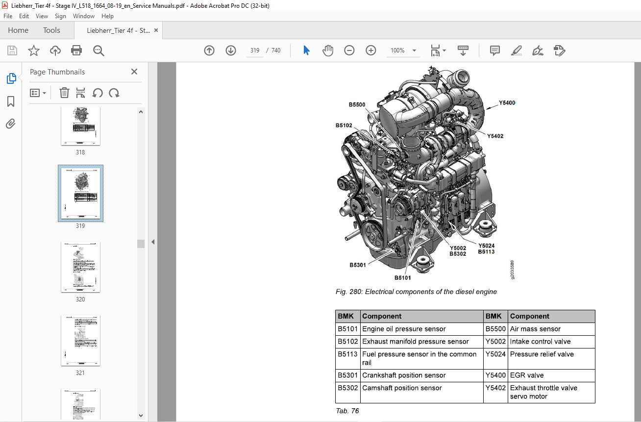
TABLE OF CONTENTS:
Liebherr L 518 1664 Wheel Loader Service Manual – PDF DOWNLOAD
010.1 Safety instructions 010-4
010.1.1 Information on these instructions 010-4
010.1.1.1 Representation of warning messages 010-4
010.1.1.2 Graphic symbols in these instructions 010-4
010.1.2 Intended use 010-5
010.1.2.1 Laws, rules, guidelines and safety regulations 010-5
010.1.2.2 Intended use 010-5
010.1.2.3 Foreseeable misuse 010-6
010.1.2.4 Operating conditions 010-6
010.1.2.5 Disposal 010-7
010.1.3 Description of staff 010-7
010.1.3.1 Personal protective equipment 010-7
010.1.3.2 Requirements for staff 010-8
010.1.3.3 Operator 010-8
010.1.3.4 Operator 010-9
010.1.3.5 Maintenance staff 010-9
010.1.3.6 Refrigeration technician 010-10
010.1.3.7 Slinger 010-11
010.1.3.8 Spotter 010-12
0101.4 Protective devices on the machine 010-12
010.1.4.1 Operator’s cab 010-12
010.1.4.2 Roll over protective structure (ROPS) 010-13
010.1.4.3 Falling object protective structures (FOPS) 010-13
0101.5 Emergency equipment on the machine 010-13
010.1.5.1 Emergency exit (standard) 010-13
010.1.5.2 Fire extinguisher (option) 010-14
010.1.6 Safe operation 010-14
010.1.6.1 Intoxicants 010-14
010.1.6.2 Dangerous fuels and operating fluids 010-14
010.1.6.3 Transporting machine 010-15
010.1.6.4 Access to machine 010-15
010.1.6.5 Machine danger zone 010-16
010.1.6.6 Visibility 010-16
010.1.6.7 Protection against vibration 010-17
010.1.6.8 Operation of machine 010-18
010.1.7 Safe maintenance 010-21
010.1.7.1 Spare parts 010-21
010.1.7.2 Heavy parts 010-21
010.1.7.3 Regular checks 010-22
010.1.8 Modifications to the machine 010-22
010.1.8.1 Modifications, add-ons and retrofittings 010-22
010.2 Special tools for maintenance and repair work 010-23
010.21 Special tools, general 010-23
010.2.2 Special tools for the engine 010-25
010.2.3 Special tools for lift cylinders 010-29
010.2.4 Special tools for tilt cylinders 010-30
010.25 Special tools for steering wheel 010-30
010.2.6 Special tools for steering cylinders 010-30
010.2.7 Special tools for the service brake 010-31
010.2.8 Special tools for the electrical system 010-31
010.2.9 Special tools for front axle 010-32
010.2.10 Special tools for rear axle 010-33
010.2.11 Special tools for the air conditioning system 010-33
010.2.12 Special tools for cab glazing 010-35
010.2.13 Special tools for the central lubrication system (Liebherr) 010-35
010.3 Standards and regulations 010-36
standard and fine threads as per DIN ISO 261 010-36
010.3.1.1 Range of application and purpose 010-36
010.3.1.2 Other applicable documents 010-36
010.3.1.3 Modifications and descriptions 010-37
010.3.1.4 Tightening torques 010-37
010.3.2 Liebherr standards for assembly instructions and tightening torques010-43
010.41 General information 010-44
0104.2 Machine out of service for an unknown period of time 010-44
0104.3 Putting the machine out of service 010-45
020.1.1 Complete machine with bucket (z-bar kinematics)
020.1.2 Working attachment: light material bucket
020.1.3 Working attachment: high dump bucket
020.1.4 Working attachment: forklift
0202.2 Fuel tank
020.2.3 Fuel level sensor
020.24 Fuel pre-filter
020.2.5 Fuel fine filter
020.2.6 Clutch
L518-1664; 020-14
020.3.2 Fan motor
L518-1664; 020-14
020.3.3 Hydraulic oil temperature sensor B8
1518-1664; 020-14
020.4 Working hydraulics 020-15
020.4.1 Working pump
1518-1664; 020-15
020.4.2 Control valve block
1518-1664; 020-15
020.4.3 Pilot control unit
1518-1664; 020-15
020.4.4 Pilot control hydro accumulator
L518-1664; 020-16
020.4.5 Stabilisation module
L518-1664; 020-16
020.46 Ride control hydro accumulator
1518-1664; 020-16
020.4.7 Lift cylinder
1518-1664; 020-16
020.4.8 Tilt cylinder
1518-1664; 020-17
020.5 Travel hydraulics 020-18
020.5.1 Travel pump
1518-1664; 020-18
020.5.2 Travel pump high pressure sensor B45
L518-1664; 020-18
020.5.3 Travel motor
1518-1664; 020-18
020.6 Hydraulic components 020-20
020.6.1 Return suction filter
1518-1664; 020-20
020.6.2 Breather filter with filler strainer
L518-1664; 020-20
020.7 Steering system 020-21
020.7.1 Servostat
1518-1664; 020-21
020.7.2 Steering cylinder
L518-1664; 020-21
020.8 Brake system 020-22
020.8.1 Drum brake
1518-1664; 020-22
020.8.2 Inch/brake unit
L518-1664; 020-22
020.9 Electrical system 020-23
020.9.1 Central control unit (Master 4)
L518-1664; 020-23
020.9.2 Compact module
L518-1664; 020-23
020.9.3 Battery
L518-1664; 020-23
020.9.4 Voltage transformer
L518-1664; 020-24
020.9.5 Reversing camera
L518-1664; 020-24
020.10 Gearbox 020-25
020.10.1 Transmission
L518-1664; 020-25
020.10.2 Output B101 speed sensor
L518-1664; 020-25
020.10.3 Hydro accumulator for external servo pressure and service brake
L518-1664; 020-25
020.11 Axles and drive shafts 020-26
020.11.1 Front axle
L518-1664; 020-26
020.11.2 Front axle with engageable differential lockout (option)
L518-1664; 020-26
020.11.3 Rear axle
L518-1664; 020-26
020.11.4 Rear axle when front axle has engageable differential lockout
(option)
L518-1664; 020-27
020.11.5 Drive shaft
L518-1664; 020-27
020.11.6 Tyres
L518-1664; 020-27
020.11.6.2 Tyres for timber work 020-28
020.11.6.3 Special tyres 020-29
020.12 Working attachment 020-30
020.12.1 Quick coupler locking hydraulic cylinder
L518-1664; 020-30
020.13 Operator’s cab, heating and air conditioning 020-31
020.13.1 Dryer
L518-1664; 020-31
copyright ® Liebherr-Werk Bischofshofen GmbH 2019
L518-1664 LIEBHERR 9
Contents
L518-1664; 020-31
020.14 Lubrication system 020-32
020.14.1 Central lubrication pump EP1
L518-1664; 020-32
020.14.2 Progressive distributor
L518-1664; 020-32
020.14.21 MXF 020-32
020.14.2.2 MX-F 25 020-32
020.14.2.3 MX-F 45 020-32
020.1424 MX-F75 020-33
020.1425 MX-F105 020-33
030 Maintenance 030-1
030.1 Maintenance and inspection schedule 030-9
030.2 Filling quantities and lubrication chart 030-14
030.2.1 Recommended lubricants
1518-1664; 030-14
030.22 Recommended operating fluids
L518-1664; 030-15
030.3 Lubricants and fuels 030-16
030.3.1 General information on lubricants and fuels 030-16
030.3.1.1 General questions 030-16
030.3.1.2 Safety data sheets 030-16
030.3.1.3 Technical data sheets 030-16
030.3.1.4 Specific Liebherr standards 030-16
030.3.2 General information on changing lubricants and fuels 030-16
030.3.3 Converting hydraulic system from mineral oils to biodegradable
hydraulic fluids 030-17
030.3.4 Diesel fuels
1518-1664; 030-17
030.3.4.1 Minimum quality requirement 030-17
030.3.4.2 Operating temperatures of diesel fuels 030-17
030.3.43 Minimum quality requirement 030-18
030.3.5 Diesel exhaust fluid
LBH/M2204905/07/211-20190801_113840/en
030.3.7 Refrigerant
030.3.8 Coolant
030.3.9 Hydraulic oil
030.3.10 Transmission
030.3.11 Axle oil
030.3.12 Brake oil
030.3.13 Lubrication grease
Maintenance tasks 030-24
0304.1 Safety precautions
0304.2 Preparatory tasks for maintenance 030-24
030.42.2 Service hatches
L 518-1664; 030-26
Contents Service manual
030.4.2.3 Turning off the battery main switch
L518-1664; 030-28
030.4.3 Overall machine 030-29
030.4.3.1 Checking the machine is in the proper condition
L518-1664; 030-29
030.4.3.2 Removing loose parts, dirt, ice and snow from
machine
L518-1664; 030-31
030.4.3.3 Cleaning the machine
1518-1664; 030-31
030.4.3.4 Replacing VCI capsules
L518-1664; 030-34
0304.3.5 Oil analyses
1518-1664; 030-36
030.4.4 Drive group 030-43
030.4.4.1 Checking diesel engine oil level
1518-1664; 030-43
030.4.4.2 Changing the engine oil
L518-1664; 030-44
030.443 Changing the diesel engine oil filter
L518-1664; 030-46
030.4.4.4 Checking the V-ribbed belt on the diesel engine
1518-1664; 030-47
030.445 Changing the V-ribbed belt on the diesel engine
L518-1664; 030-48
0304.46 Checking diesel engine valve clearance
1518-1664; 030-50
0304.4.7 Diesel engine: changing the oil separator filter
cartridge
1518-1664; 030-53
0304.4.8 Diesel engine: Checking the crankcase bleeder
system
L518-1664; 030-53
030.4.4.9 Diesel engine: Checking the glow plugs
1518-1664; 030-54
030.4.4.10 Draining condensate and sediment from the fuel tank
1518-1664; 030-55
030.4.4.11 Draining off condensate from the fuel pre-filter
1518-1664; 030-56
030.4.4.12 Changing the fuel pre-filter element
L518-1664; 030-57
030.4.4.13 Changing the fuel fine filter element
1518-1664; 030-59
030.4.4.14 Bleeding the fuel system
1518-1664; 030-60
copyright ® Liebher-Werk Bischofshofen GmbH 2019
12 LIEBHERR L518-1664
LBH/M2204905/07/211-20190801_113840/en
030.4.4.16 Cleaning the service cover and dust discharge valve
030.4.4.17 Cleaning or changing main element of air filter
030.4.4.18 Changing the safety element of the air filter system
030.4.4.19 Checking that the engine intake and exhaust system
030.4.4.20 Cleaning or changing the diesel particulate filter
Cooling system 030-73
030.4.5.1 Checking the coolant level in the cooling system
030.4.5.2 Checking coolant antifreeze and corrosion inhibitor
030.4.5.3 Cleaning the cooling system
030.4.5.4 Changing coolant in cooling system
Working hydraulics 030-86
030.46.1 Cleaning and lubricating the pilot control unit
Hydraulic components 030-87
030.4.7.1 Checking oil level in hydraulic tank
030.4.7.2 Draining off condensate and sediment from the
030.4.7.3 Changing the hydraulic tank return suction filter
030.4.7.4 Changing the hydraulic tank breather filter
030.4.7.5 Hydraulic tank: analysing oil
030.4.7.6 Hydraulic tank: changing oil
Steering system 030-96
030.4.8.1 Steering: Checking the function
L518-1664; 030-96
030.4.8.2 Lubricating the steering cylinder bearing
1518-1664; 030-96
030.4.9 Brake system 030-97
030.4.9.1 Testing service brake and parking brake
L518-1664; 030-97
030.4.9.2 Checking the oil level in the brake system
L518-1664; 030-99
030.4.9.3 Checking the gap and wear on the service brake
linings
L518-1664; 030-100
0304.94 Checking service brake discs for wear
L518-1664; 030-102
030.4.10 Electrical system 030-104
030.4.10.1 Checking function of the lighting and horn
1518-1664; 030-104
0304.10.2 Checking the battery fluid levels and terminals
L518-1664; 030-105
030.4.10.3 Control lever: Change the travel direction switch
rocker and cap.
L518-1664; 030-107
030.4.11 Gearbox 030-109
0304.11.1 Transmission: checking the oil level
L518-1664; 030-109
030.4.11.2 Changing transmission oil
L518-1664; 030-109
030.4.12 Axles and drive shafts 030-111
0304.12.1 Checking the axle oil levels
L518-1664; 030-111
030.4.12.2 Changing the axle oil
L518-1664; 030-113
030.4.12.3 Lubricating the rear axle kingpin bearings
L518-1664; 030-116
030.4.12.4 Checking the fitting of the rear axle kingpin bearings
and steering rod taper connections
L518-1664; 030-116
0304.12.5 Checking the tightening torque of the front axle
fastening bolts
L518-1664; 030-117
0304.12.68 Checking the drive shaft
L518-1664; 030-118
030.4.12.7 Checking the tyre pressure
1518-1664; 030-119
Steel parts of the basic machine 030-120
030.4.13.1 Lubricating the articulated bearing and rear oscil-
030.4.13.2 Lubricating the articulation stops
030.4.13.3 Lubricating the moving parts of the cooler hood with
030.4.13.4 Lubricating the moving parts of the engine bonnet
030.4.13.5 Cleaning and maintaining the seals of the service
Working attachment 030-124
030.4.14.1 Lubricating the lift arms and working attachment
030.4.14.2 Checking the lift arm bucket bearing bushings
030.4.14.3 Checking lift arm bucket stops
030.4.14.4 Lubricating and testing the bearings on the quick
Operator’s cab, heating and air conditioning 030-127
030.4.15.1 Cleaning the cab air filter
030.4.15.2 Changing the cab air filter
030.4.15.3 Safety belt: checking condition and function
030.4.15.4 Testing the windscreen washer system
030.4.15.5 Filling windscreen washer fluid in the windscreen
030.4.15.6 Lubricating the locking mechanism and cylinder of
030.4.15.7 Cleaning and maintaining the seals of the operator’s
L518-1664; 030-131
030.4.15.8 Checking the indicator bead in the air conditioning
dryer-collector unit
L518-1664; 030-132
030.4.15.9 Heating and air conditioning unit: Testing function
1518-1664; 030-133
030.4.16 Lubrication system 030-134
030.4.16.1 Checking the grease level in the reservoir of the
central lubrication system
L518-1664; 030-134
030.4.16.2 Central lubrication system: Checking the pipes,
hoses and lubrication points for leaks and damage
L518-1664; 030-135
030.4.16.3 Central lubrication system: Checking the lubrication
of the bearings
1518-1664; 030-136
030.5 Testing and adjustment checklist
L518-1664; 030-137
030.6 Testing and adjustment tasks 030-142
030.6.1 Safety precautions
L518-1664; 030-142
030.6.2 Overall machine 030-142
030.6.2.1 Preparing for adjustment procedures
1518-1664; 030-142
0306.2.2 Hydraulic oil and coolant: operating temperature
L518-1664; 030-144
030.6.2.3 Service management
L518-1664; 030-145
030.6.3 Drive group 030-146
030.6.3.1 Pedals: calibration
L518-1664; 030-146
030.6.3.2 Diesel engine speed
1518-1664; 030-148
030.6.3.3 Reading the diesel engine service files
L518-1664; 030-148
030.6.4 Cooling system 030-150
030.6.4.1 Fan motor: fan speed proportional solenoid
1518-1664; 030-150
030.6.5 Working hydraulics 030-153
030.6.5.1 Control valve block: secondary pressure relief valves
1518-1664; 030-153
0306.5.2 Control valve block: working hydraulics LS pressure
relief valve
1518-1664; 030-155
030.6.5.4 Ride control hydro accumulator (option): nitrogen
Hydraulic components 030-161
030.6.6.1 Checking the hydraulic lines for damage
Travel hydraulics 030-166
030.6.7.1 Travel pump high pressure sensor B102: Deviation
030.6.7.2 Travel pump replenishing pressure relief valve
030.6.7.3 Travel pump: high pressure relief valves
030.6.7.4 Travel pump: pressure cut-off
030.6.7.5 Travel pump: manual block curve calibration
030.6.7.6 Travel pump: automatic block curve calibration (from
030.6.7.7 Travel motor: manual calibration (maximum swivel
030.6.7.8 = Travel motor: manual calibration (minimum swivel
Brake system 030-180
030.6.8.1 Inching brake pedal: basic setting
030.6.8.2 Angle sensor for inching function: checking basic
030.6.8.3 Service brake: brake pressure in 1st brake circuit
030.6.8.4 Service brake: pressure reducing valve for service
Electrical system 030-186
030.6.9.1 Central control unit (Master4) Creating a Servicefile
030.6.9.2 Updating the central controller software
030.6.9.3 Setting the IP addresses of the central control unit
(Master4)
1518-1664; 030-191
030.6.9.4 Resetting the central control unit (Master4)
1518-1664; 030-194
030.6.9.5 Addressing CAN module and checking system infor-
mation
1518-1664; 030-196
030.6.10 Gearbox 030-198
030.6.10.1 Travel hydraulics: external servo pressure reducing
valve
L518-1664; 030-198
0306.10.2 Hydro accumulator for external servo pressure and
service brake: nitrogen filling
1518-1664; 030-199
030.6.11 Axles and drive shafts 030-202
030.6.11.1 Tyres: setting radius
L518-1664; 030-202
030.6.12 Operator’s cab, heating and air conditioning 030-203
030.6.12.1 Formatting the display and reinstalling the software
(Display4)
1518-1664; 030-203
040 Drive group 040-1
040.1 Engine 040-2
040.1.1 Diesel engine overview
1518-1664; 040-2
040.1.2 Electrical components of the diesel engine
1518-1664; 040-6
040.1.3 Fuel system 040-16
040.1.3.1 Overview of the fuel system
L518-1664; 040-16
040.1.3.2 Fuel level sensor
1518-1664; 040-17
040.1.3.3 Fuel pre-filter
L518-1664; 040-19
040.1.3.4 Fuel fine filter
1518-1664; 040-20
040.1.4 Air filter system 040-21
040.1.4.1 Air filter
1518-1664; 040-21
040.1.5 Exhaust system 040-21
040.1.5.1 Overview of exhaust system
L518-1664; 040-2
040.1.5.3 SCR system
1518-1664; 040-28
040.1.5.4 Sampling module
L518-1664; 040-32
040.2 Clutch
L518-1664; 040-34
050 Cooling system 050-1
050.1 Overview of the cooling system
1518-1664; 050-2
050.2 Cooling system hydraulics 050-4
050.2.1 Overview of cooling system hydraulics
L518-1664; 050-4
050.2.2 Fan pump
L518-1664; 050-7
050.2.3 Fan motor
L518-1664; 050-8
050.3 Cooling system electronics 050-10
050.3.1 General overview of electronic control system
L518-1664; 050-10
050.3.2 Temperature sensor for coolant
L518-1664; 050-13
050.3.3 Hydraulic oil temperature sensor
L518-1664; 050-14
050.34 Temperature sensor for charge air
L518-1664; 050-15
050.4 Cooler 050-17
0504.1 Cooler unit
L518-1664; 050-17
050.5 Reversible fan drive 050-18
0505.1 Overview of reversible fan drive
L518-1664; 050-18
050.5.2 Fan reversal valve block
L518-1664; 050-21
060 Working hydraulics 060-1
060.1 Overview of working hydraulics
1518-1664; 060-2
060.2 Working pump
1518-1664; 060-8
060.3 Control block
L518-1664; 060-9
060.4 Pilot control 060-19
060.4.1 Overview of the pilot control unit
L518-1664; 060-20
060.4.2 Pilot control unit
L518-1664; 060-24
060.4.3 Pilot pressure for solenoid valve
L518-1664; 060-26
060.5 Ride control 060-28
060.5.1 Overview of ride control system
1518-1664; 060-28
060.5.2 Stabilisation module
L518-1664; 060-32
060.6 Pipe break protection 060-37
060.6.1 Pipe break protection: overview
1518-1664; 060-37
060.6.2 Valve block for pipe break protection
L518-1664; 060-39
060.6.3 Solenoid valve for release of the ride control
1518-1664; 060-40
070 Travel hydraulics 070-1
070.1 Overview of travel hydraulics
L518-1664; 070-2
070.2 Travel pump
L518-1664; 070-9
070.3 Travel motors 070-24
070.3.1 Travel motor
L518-1664; 070-24
080 Hydraulic components 080-1
080.1 Hydraulic system: overview
L518-1664/0-48858; 080-2
080.2 Hydraulic system: overview
L518-1664/48859-; 080-5
080.3 Hydraulic tank 080-9
080.3.1 Overview of the hydraulic tank
L518-1664; 080-9
080.3.2 Return-suction filter
1518-1664; 080-12
080.3.3 Breather filter
L518-1664; 080-1
090.1 Steering system overview
1518-1664; 090-2
090.2 Servostat
1518-1664; 090-6
100 Brake system 100-1
100.1 Overview of brake system
1L518-1664/0-48858; 100-2
100.2 Overview of brake system
L518-1664/48859-; 100-8
100.3 Service brake 100-16
100.3.1 Inch/brake unit
L518-1664; 100-15
100.3.2 Inching function angle sensor
L518-1664; 100-22
100.3.3 Brake light pressure switch
L518-1664; 100-23
100.34 Drum brake
L518-1664; 100-25
100.4 Parking brake 100-29
100.4.1 Parking brake solenoid valve
L518-1664; 100-29
100.4.2 Orifice bypass solenoid valve
L518-1664/48859-; 100-30
110 Electrical system 110-1
110.1 Overview of the electrical system
1518-1664; 110-2
110.2 Lighting
L518-1664; 110-6
110.3 Circuit diagrams
L518-1664; 110-8
110.4 Electronic control unit 110-10
110.4.1 General overview of the electronic control system
L518-1664; 110-10
110.4.2 Central control unit (Master4)
L518-1664; 110-11
110.4.3 Modules 110-16
110.4.3.1 Overview of compact module
1518-1664; 110-16
110.4.3.2 Compact module
1518-1664; 110-17
copyright ® Liebherr-Werk Bischofshofen GmbH 2019
L518-1664 LIEBHERR 2
Contents Service manual
110.5 Electrical components of the driver’s cab 110-23
110.5.1 Overview of electrical components in the operator’s cab
1518-1664; 110-23
110.5.2 Fuse boards
L518-1664; 110-25
110.5.3 Door contact switch
L518-1664; 110-27
110.6 Electrical components in the rear section 110-28
110.6.1 Battery installation
L518-1664; 110-28
110.7 Rear area monitoring with camera 110-30
110.7.1 Overview of rear area monitoring with camera
L518-1664; 110-30
110.7.2 Camera
1518-1664; 110-31
120 Gearbox 120-1
120.1 Overview of the transmission
L518-1664; 120-2
120.2 Transmission hydraulics 120-7
120.2.1 Overview of transmission hydraulics
1518-1664; 120-7
120.2.2 Gear shifting
L518-1664; 120-13
120.2.3 Valve block for pressure reducing valves
L518-1664; 120-15
120.2.4 Travel motor bypass solenoid valve
1518-1664; 120-17
120.3 Transmission electronics 120-19
120.3.1 Gearbox: electrical system
L518-1664; 120-19
120.3.2 Output speed sensor
1518-1664; 120-21
120.3.3 Hall sensor for gear indicator
L518-1664; 120-22
130 Axles and drive shafts 130-1
130.1 Axles 130-2
130.1.1 Front axle
1518-1664; 130-2
130.1.2 Rear axle
L518-1664; 130-
130.1.3.1 Overview of engageable differential lockout
1518-1664; 130-6
130.1.3.2 Valve block for parking brake and differential lockout
L518-1664; 130-8
130.2 Cardan shafts 130-10
130.2.1 Drive shaft
L518-1664; 130-10
140 Steel parts of the basic machine 140-1
140.1 Vehicle frame 140-2
140.1.1 Articulation bearing
L518-1664; 140-2
140.1.2 Articulation lock
L518-1664; 140-3
150 Working attachment 150-1
150.1 Lift arms for Z kinematics 150-2
160.1.1 Lift arms for Z kinematics
L518-1664; 150-2
150.2 Quick coupler 150-4
150.2.1 Quick coupler
L518-1664; 150-4
160.2.2 Quick coupler hydraulics 150-5
160.2.2.1 Overview of quick coupler hydraulics
L518-1664/0-51094; 150-5
150.2.2.2 Overview of quick coupler hydraulics
L518-1664/51095-; 150-7
150.2.2.3 Valve block for quick coupler
L518-1664; 150-9
160 Operator’s cab, heating and air conditioning 160-1
160.1 Overview of the operator’s cab, heating and air conditioning unit
L518-1664; 160-2
160.2 Display and control elements 160-4
160.2.1 Display
L518-1664; 160-4
160.2.2 Control lever
L518-1664; 160-4
160.2.3 Accelerator pedal
L518-1664; 160-6
160.3 Heating, ventilation, air conditioning 160-8
160.3.2 Heating and air conditioning unit 160-13
160.3.2.1 Heating and air conditioning unit
L518-1664; 160-13
160.3.2.2 Blower
L518-1664; 160-16
160.4 Air conditioning 160-17
160.4.1 Air conditioning (optional)
L518-1664; 160-17
160.4.2 Air conditioning compressor
1518-1664; 160-18
160.4.3 Condenser
L518-1664; 160-20
160.4.4 Dryer-collector unit
1518-1664; 160-20
160.4.5 Air conditioning pressure switch
L518-1664; 160-22
170 Lubrication system 170-1
170.1 Liebherr automatic central lubrication system 170-2
170.1.1 Automatic central lubrication system: overview
L518-1664; 170-2
170.1.2 Central lubrication pump EP-1
1518-1664; 170-6
170.1.3 Progressive distributor MX-F
L518-1664; 170-9
190 Options 190-1
190.1 LIiDAT 190-2
190.1.1 Overview of LiDAT
1518-1664; 190-2
190.1.2 LiDAT on machine
1518-1664; 190-4
200 Diagnosis 200-1
200.1 Malfunctions 200-2
200.1.1 Warning symbols 200-2
200.1.2 SCR system warning symbols 200-2
200.1.3 Service code indicator in the display 200-3
200.2 Troubleshooting 200-5
200.2.1.1 Fuses on fuse board in operator’s cab 200-5
200.2.1.2 Fuses in right of engine compartment 200-8
VIDEO PREVIEW OF THE MANUAL:
PLEASE NOTE:
- This is the SAME MANUAL used by the dealerships to diagnose your vehicle
- No waiting for couriers / posts as this is a PDF manual and you can download it within 2 minutes time once you make the payment.
- Your payment is all safe and the delivery of the manual is INSTANT – You will be taken to the DOWNLOAD PAGE.
- So have no hesitations whatsoever and write to us about any queries you may have : heydownloadss @gmail.com
S.V


