Land Rover V8 ENGINE MANAGEMENT SYSTEM ON-BOARD DIAGNOSTICS Manual PDF
$26.95
Land Rover V8 ENGINE MANAGEMENT SYSTEM ON-BOARD DIAGNOSTICS Manual – PDF DOWNLOAD
Description
Land Rover V8 ENGINE MANAGEMENT SYSTEM ON-BOARD DIAGNOSTICS Manual – PDF DOWNLOAD
FILE DETAILS:
Land Rover V8 ENGINE MANAGEMENT SYSTEM ON-BOARD DIAGNOSTICS Manual – PDF DOWNLOAD
Language : English
Pages : 124
Downloadable : Yes
File Type : PDF
IMAGES PREVIEW OF THE MANUAL:
TABLE OF CONTENTS:
Land Rover V8 ENGINE MANAGEMENT SYSTEM ON-BOARD DIAGNOSTICS Manual – PDF DOWNLOAD
Vehicle Coverage:
LR3 2005 MY Onwards
Range Rover 2006 MY Onwards
Range Rover Sport 2005 MY Onwards
1 Contents 2
2 Introduction 6
2.5 Inputs and Outputs 6
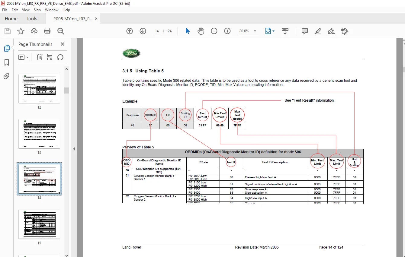
3 Mode $06 Data 9
4 Onboard Monitoring 9
4.1 Catalyst Monitoring 19
4.1.1 Description 19
4.1.2 Monitoring Structure 20
4.1.3 Drive Cycle Information 21
4.2 Misfire Monitoring 22
4.2.1 Description 22
4.2.2 Strategy Description 24
4.2.3 Drive Cycle Information 30
4.3 Evaporative Emission System Monitoring 31
4.3.1 Schematic 31
4.3.2 Description 32
4.3.3 Typical monitoring results 33
4.3.4 Strategy Flowchart 34
4.3.5 Diagnosis Frequency and MIL Illumination 36
4.3.6 Evaporative Emission Canister Purge Valve 37
4.3.7 Purge Flow Strategy Flowchart 38
4.3.8 Drive Cycle Information 42
4.4 Fuel System Monitoring 43
4.4.1 Description 43
4.4.2 Strategy Flowchart 43
4.4.3 Drive Cycle Information 45
4.5 Exhaust Gas Recirculation (EGR) Monitoring 46
4.5.1 Description 46
4.6 Oxygen Sensor Monitoring 49
4.6.1 Upstream Oxygen Sensor High Low Monitor 49
4.6.2 Upstream Oxygen Sensor Slow Response 50
4.6.3 Upstream Oxygen Sensor Slow Activation 52
4.6.4 Downstream Oxygen Sensor High or Low Monitor 53
4.6.5 Downstream Oxygen Sensor Stuck Monitor 55
4.6.6 Downstream Oxygen Sensor Rationality Check 56
4.6.7 Drive Cycle Information 62
4.7 Thermostat Monitoring 63
System Schematic 63
Land Rover Revision Date: March 2005 Page 3 of 124
4.7.2 Description 63
4.8 Positive Crankcase Ventilation (PCV) System Monitoring 65
4.8.1 Description 65
4.8.2 PCV Valve Location and Fixing (4.4L V8) 65
4.8.3 PCV Valve Location and Fixing (4.2L V8 Supercharged) 66
4.9 Idle Speed Control 67
4.9.1 Description 67
4.10 Crankshaft Position and Engine Speed Sensor 68
4.10.1 Description 68
4.11 Camshaft Position Sensors 69
4.11.1 Description 69
4.12 Engine Coolant Temperature (ECT) Sensor 71
4.12.1 Sensor Stuck 71
4.12.2 Range or Performance Failure 71
4.12.3 Time to Closed Loop Fuelling 71
4.12.4 Range/Performance Flow chart 72
4.13 Manifold Absolute Pressure Sensors 74
4.13.1 High or Low Input Failure and Ground Monitor 74
4.13.2 Range / Performance Failure 74
4.13.3 Flow Chart 75
4.14 Mass Airflow Sensor 78
4.14.1 High or Low Input Failure and Ground Monitor 78
4.14.2 Range / Performance Failure 78
4.14.3 Flow Chart 79
4.15 Barometric Pressure Sensor 81
4.15.1 High /Low Input Failure 81
4.15.2 Range / Performance Failure 81
4.16 Fuel Rail Pressure Sensor 83
4.17 Intake Air Temperature Sensors 84
4.17.1 Sensor Stuck 84
4.17.2 Range or Performance Failure 84
4.17.3 Range/Performance Flow chart 85
4.18 Engine Oil Temperature Sensor 88
4.18.1 Sensor Stuck 88
4.18.2 Range or Performance Failure 88
4.18.3 Range/Performance Flow Chart 89
4.19 Fuel Rail Temperature Sensor 91
4.19.1 Sensor Stuck 91
4.19.2 Range or Performance Failure 91
4.19.3 Range /Performance Flow Chart 92
4.19.4 Sensor Stuck Flow Chart 93
Land Rover Revision Date: March 2005 Page 4 of 124
4.20 Knock Sensor 95
4.20.1 Description 95
4.21 ECM Power Supplies 96
4.21.1 Description 96
4.22 Engine Control Module Self Test 97
4.22.1 Description 97
4.23 Engine Starting 99
4.23.1 Crank request Signal 99
4.23.2 Park / Neutral Switch 99
4.23.3 Starter relay 99
4.24 Accelerator Pedal Position Sensor 101
4.24.1 Description 101
4.25 Throttle Control System 102
4.25.1 Description 102
4.26 Torque Monitoring 104
4.26.1 Description 104
4.27 Vehicle Speed Signal 105
4.27.1 Description 105
4.28 Fuel Injectors 106
4.28.1 Description 106
4.29 Ignition Amplifiers / Coils 108
4.29.1 Description 108
4.30 Variable Valve Timing 110
4.30.1 Hardware Check 110
4.30.2 Camshaft Position 110
4.31 Controller Area Network System 112
4.31.1 Invalid signal Error 112
4.31.2 Vehicle Options Error 112
4.31.3 VIN Mismatch 112
4.31.4 Loss of Communications 112
4.32 Fuel Level Sensor 116
4.32.1 Fuel level stuck monitor 116
4.32.2 Fuel level noisy monitor 116
4.33 Engine Off Timer 117
4.33.1 Description 117
4.34 Ambient Air Temperature 118
4.34.1 Description 118
4.35 Low Range Gear Monitor 120
4.35.1 Description 120
4.36 Viscous Fan 122
4.36.1 Description 122
Land Rover Revision Date: March 2005 Page 5 of 124
4.37 Supercharger Intercooler Water Pump 123
4.37.1 Description 123
4.38 Air Conditioning (A/C) System Component Monitoring 124
S.V 28/02/2025