Land Rover 2.0L I4 GTDi Engine Management System ON BOARD DIAGNOSTIC Manual PDF
$28.95
Land Rover 2.0L I4 GTDi Engine Management System ON BOARD DIAGNOSTIC Manual – PDF DOWNLOAD
Description
Land Rover 2.0L I4 GTDi Engine Management System ON BOARD DIAGNOSTIC Manual – PDF DOWNLOAD
FILE DETAILS:
Land Rover 2.0L I4 GTDi Engine Management System ON BOARD DIAGNOSTIC Manual – PDF DOWNLOAD
Language : English
Pages : 173
Downloadable : Yes
File Type : PDF
IMAGES PREVIEW OF THE MANUAL:
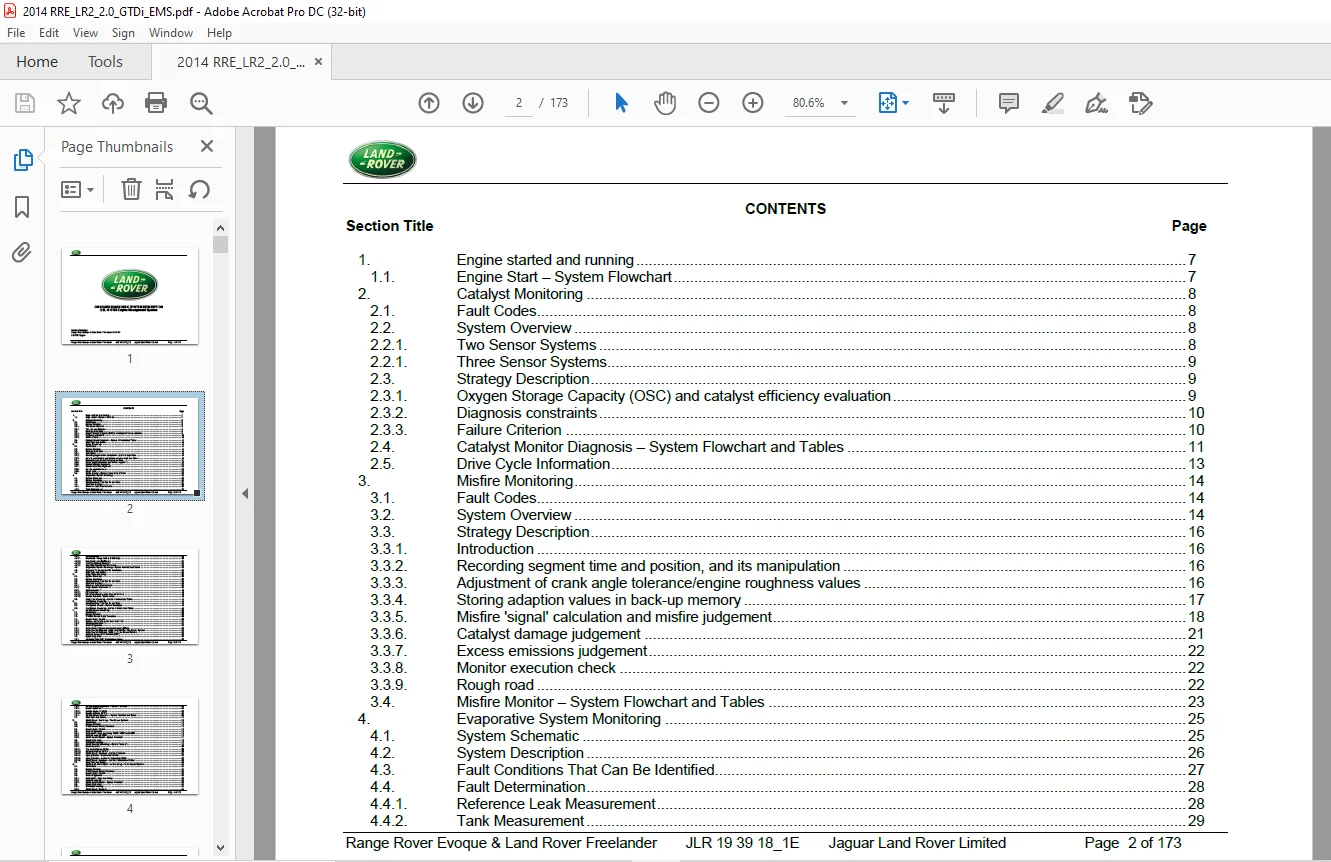
TABLE OF CONTENTS:
Land Rover 2.0L I4 GTDi Engine Management System ON BOARD DIAGNOSTIC Manual – PDF DOWNLOAD
1 Engine started and running 7
11 Engine Start – System Flowchart 7
2 Catalyst Monitoring 8
21 Fault Codes 8
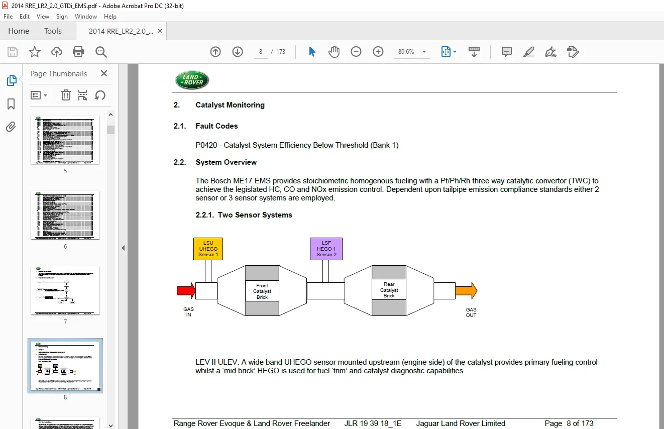
22 System Overview 8
221 Two Sensor Systems 8
221 Three Sensor Systems 9
23 Strategy Description 9
231 Oxygen Storage Capacity (OSC) and catalyst efficiency evaluation 9
232 Diagnosis constraints 10
233 Failure Criterion 10
24 Catalyst Monitor Diagnosis – System Flowchart and Tables 11
25 Drive Cycle Information 13
3 Misfire Monitoring 14
31 Fault Codes 14
32 System Overview 14
33 Strategy Description 16
331 Introduction 16
332 Recording segment time and position, and its manipulation 16
333 Adjustment of crank angle tolerance/engine roughness values 16
334 Storing adaption values in back-up memory 17
335 Misfire ‘signal’ calculation and misfire judgement 18
336 Catalyst damage judgement 21
337 Excess emissions judgement 22
338 Monitor execution check 22
339 Rough road 22
34 Misfire Monitor – System Flowchart and Tables 23
4 Evaporative System Monitoring 25
41 System Schematic 25
42 System Description 26
43 Fault Conditions That Can Be Identified 27
44 Fault Determination 28
441 Reference Leak Measurement 28
442 Tank Measurement 29
Range Rover Evoque & Land Rover Freelander JLR 19 39 18_1E Jaguar Land Rover Limited Page 3 of 173
443 Fault Assessment 30
4431 Small Leak / Rough Leak (> 0040 inch) 30
4432 Very Small Leak (0020 inch) 31
4433 Fuel Cap Warning Message 32
4434 Filler Cap Removal and Re-Fueling 32
45 Evaporative System Monitoring – System Flowchart and Tables 33
46 Diagnosis Frequency and MIL Illumination 36
47 Drive Cycle Information 36
5 Purge Valve Monitoring 38
51 System Schematic 38
52 System Description 38
53 Fault Conditions That Can Be Identified 39
54 Fault Determination 39
541 Reference Leak Measurement 39
542 Purge System Measurement 39
543 Fault Assessment 40
5431 CPV stuck open 40
5432 CPV stuck closed or purge lines are blocked 40
5433 Flow performance / disconnected 40
55 Purge Flow Monitoring – System Flowchart and Tables 41
6 Fuel System Monitoring 46
61 Fault Conditions That Can Be Identified 46
62 Fuel System Monitor – System Description 46
63 Fuel System Monitoring – System Flowchart and Tables 49
7 UHEGO Sensor Monitoring 60
71 Fault Codes 60
72 System Overview 60
73 ‘UHEGO Sensor Ready’ Conditions 60
74 Sensor Heater Control 60
741 Valid sensor resistance has been measured 61
742 Dew point assessment 61
75 Heater Diagnostics 62
751 Heater Powerstage/control circuit analysis (P0606) 62
752 Heater Control Diagnosis (P00D1 and P0135) – Two Sensor Systems 62
753 Heater Control Diagnosis (P00D1) – Three Sensor Systems 62
754 Heater Influence on Nernst Cell (P2231) 63
76 Signal Diagnostics 63
761 Integrated Circuit (IC) Electrical monitoring 63
Range Rover Evoque & Land Rover Freelander JLR 19 39 18_1E Jaguar Land Rover Limited Page 4 of 173
762 UHEGO Signal Diagnostics – System Flowchart 65
763 Sensor Dynamics 66
7631 Voltage diagnosis P0134 66
7632 Sensor response P0133 66
764 UHEGO Sensor Dynamics – System Flowchart and Tables 68
77 Drive Cycle Information 74
8 HEGO Sensor Monitoring – Two Sensor Systems 75
81 Fault Codes 75
82 System Overview 75
83 ‘HEGO Sensor Ready’ Conditions 75
84 Sensor Heater Control 76
85 Heater Diagnostics 76
851 Heater power stage monitoring P0036, P0037 and P0038 76
852 Heater monitoring P0054 76
853 HEGO Heater Monitor – System Flowchart 77
86 Signal Diagnostics 78
861 Electrical monitoring 78
862 HEGO Electrical Monitoring – System Flowchart 79
863 Sensor dynamics 80
8631 Transient response P013A 80
8632 Delayed response P013E 80
8633 HEGO Sensor Dynamics – System Flowchart 81
8634 Ageing Monitor – sensor stuck P0140 82
8635 Ageing Monitor – sensor not responding P0139 82
8636 HEGO Sensor Dynamics – System Flowchart and Tables 83
87 Drive Cycle Information 90
9 HEGO (LSF AND LSH) Sensor Monitoring – Three Sensor Systems 91
91 Fault Codes 91
92 System Overview 91
93 ‘HEGO Sensor Ready’ Conditions 92
94 Sensor Heater Control 92
95 Heater Diagnostics 92
951 Heater power stage monitoring 92
952 Heater monitoring 92
953 HEGO Heater Monitor – System Flowchart 93
96 Signal Diagnostics 94
961 Electrical monitoring 94
962 HEGO Sensor dynamics 94
Range Rover Evoque & Land Rover Freelander JLR 19 39 18_1E Jaguar Land Rover Limited Page 5 of 173
9621 Transient response 95
9622 Delayed response 95
9623 Range or signal stuck 95
9624 Delayed Response – System Flowchart 96
9625 Transient response – System Flowchart 97
9626 Range or Signal Stuck – System Flowchart and Tables 98
97 Drive Cycle Information 105
10 Individual Cylinder AFR Monitor 106
101 Fault Conditions That Can Be Identified 106
102 System Description 106
103 Fault Decision 106
104 Individual Cylinder AFR Monitor – System Flowchart and Tables 107
11 Engine Cooling System – Thermostat Monitoring – P0128 109
111 System Schematic 109
112 Typical Time to Detection for a failed Thermostat during Normal Driving 110
113 Thermostat Monitoring – System Flowchart and Tables 111
12 Comprehensive Component Monitoring 113
121 Intake Air Temperature Sensor Monitor 113
1211 TMAP / TFA1 (Pre-Throttle) Intake Air Temperature Sensor Monitor 113
12111 Fault Conditions That Can Be Identified 113
12112 Electrical Monitor (P007D, P007C and P007A) 113
12113 Rationality Monitor (High/Stuck P007B) 113
12114 Cold Start Monitor (P011C) 114
12115 TFA1 Monitoring – System Flowchart and Tables 115
1212 TMAF / TFA2 (Post air filter) Intake Air Temperature Sensor Monitor 119
12121 Fault Conditions That Can Be Identified 119
12122 Electrical Monitor (P0113, P0112 and P0110) 119
12123 Rationality Monitor (P0111) 119
12124 Cold Start Monitor (P00CE) 119
12125 TFA2 Monitoring – System Flowchart and Table 120
122 MAF – Air Flow Monitor 122
1221 Fault Conditions That Can Be Identified 122
1222 Range Check (P0103 / P0102) 122
1223 Signal Check (P0100) 122
1224 Rationality Monitor (P0101) 122
1225 MAF Monitoring – System Flowchart and Table 123
123 MAP Pressure Monitor 125
1231 Fault Conditions That Can Be Identified 125
Range Rover Evoque & Land Rover Freelander JLR 19 39 18_1E Jaguar Land Rover Limited Page 6 of 173
1232 Electrical Monitor (P0108/P0107) 125
1233 Range Check, Rationality and Signal Monitor (P0106) 125
1234 MAP Monitoring – System Flowchart and Tables 126
124 Coolant Temperature Sensor Monitor 129
1241 Fault Conditions That Can Be Identified 129
1242 Electrical Monitor (P0118/P0117) 129
1243 Rationality Monitor (P0116) 129
1244 Cold Start Monitor (P011B) 129
1245 Coolant Sensor Monitor – System Flowchart and Tables 130
125 Radiator Out Temperature Sensor Monitor 133
1251 Fault Conditions That Can Be Identified 133
1252 Range Monitor (P2185, P2184) 133
1253 Rationality Monitor (P2183) 133
1254 Radiator Out Temperature Sensor Monitor – System Flowchart and Table 135
13 Additional tables 137
131 Cold Start Emission Reduction Strategy Performance Tables 137
132 Barometric Pressure Sensor Monitoring Table 141
133 Cam and Crankshaft Sensor Monitoring Tables 142
134 Variable Valve Timing Monitoring Tables 146
135 Idle Speed Control Monitoring Table 150
136 Wastegate Monitoring Table 151
137 Oil Temperature Sensor Monitoring Table 152
138 Ambient Temperature Sensor Monitoring Tables 153
139 Knock Sensor Monitoring Table 154
1310 Throttle Monitoring Tables 155
1311 ECM Monitoring Tables 158
1312 Vehicle Speed Determination Monitoring Table 159
1313 Network Management Monitoring Tables 160
14 Additional Information 162
141 Diagnostic Test Mode Compliance 162
142 Stored Engine Conditions – Mode$02 162
143 Inspection and Maintenance Test Readiness Setting 163
1431 Introduction 163
1432 Readiness Setting 163
144 Communication of Monitor Test Results – Mode$06 165
145 Drawing and Location of the Malfunction Indicator Light 170
146 Location of the Data Link Connector 172
S.V 28/02/2025