Kubota SVL97-2 Compact Track Loader Workshop Manual – PDF
$30.95
Kubota SVL97-2 Compact Track Loader Workshop Manual – PDF DOWNLOAD
Description
Kubota SVL97-2 Compact Track Loader Workshop Manual – PDF DOWNLOAD
FILE DETAILS:
Kubota SVL97-2 Compact Track Loader Workshop Manual – PDF DOWNLOAD
Language : English
Pages : 588
Downloadable : Yes
File Type : PDF
IMAGES PREVIEW OF THE MANUAL:
TABLE OF CONTENTS:
Kubota SVL97-2 Compact Track Loader Workshop Manual – PDF DOWNLOAD
SAFETY FIRST1-1
1 Working precautions 1-1
2 Preparing for emergencies 1-1
3 Working cautions 1-2
4 Starting machine safely 1-2
5 Preventing fires1-3
6 Preventing acid burns1-3
7 Avoiding high pressure fluid1-3
8 Avoiding hot exhaust 1-4
9 Cleaning exhaust filter 1-4
SAFETY LABELS 1-5
1 Safety labels placement 1-5
2 Safety labels maintenance 1-11
2 GENERAL
GENERAL WORKING INSTRUCTIONS 2-1
1 General working precautions2-1
2 Tightening bolts and nuts2-1
3 Applying thread-locking fluid2-1
4 Installing circlips 2-2
5 Installing spring pins 2-2
6 Handling split pin 2-2
7 Handling chain joint and split pin 2-2
8 Handling liquid gasket 2-3
9 Replacing O-rings2-3
10 Replacing oil seals2-3
11 Replacing floating seals 2-4
12 Connecting hydraulic hoses 2-4
13 Wrapping thread seal tape2-4
14 Installing elbows with male seat 2-4
15 Connecting and disconnecting quick hose couplings 2-5
16 Handling the battery 2-5
17 Handling wire harness 2-5
18 Handling fuses2-7
19 Handling connectors2-7
20 Wiring color2-8
21 Washing the machine with a high pressure washer 2-8
22 Dispose fluids correctly2-9
PRELIMINARY WORKING INSTRUCTIONS 2-11
1 Vacuuming the hydraulic tank 2-11
2 Tilting up the cab 2-11
3 Opening the rear bonnet 2-11
4 Tilting the radiator 2-12
5 Locking the lift arm 2-13
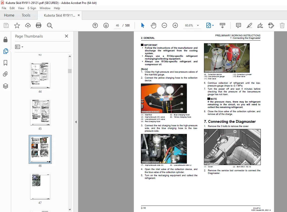
6 Collecting refrigerant 2-13
7 Connecting the Diagmaster 2-14
CONCLUDING WORKING INSTRUCTIONS 2-17
1 Bleeding the air from the hydraulic cylinder2-17
2 Charging refrigerant2-17
TIGHTENING TORQUES 2-19
1 Bolts and nuts tightening torque 2-19
2 Stud bolts tightening torque2-19
3 Hydraulic hose fitting tightening torque 2-20
SVL97-2 iii
4 Hydraulic hoses tightening torque (taper thread) 2-20
5 Locknuts of adapters with O-ring tightening torque (straight thread)2-20
6 Adapters tightening torque (taper thread)2-21
7 Hose clamps tightening torque 2-21
GENERAL MACHINE INFORMATION 2-23
1 Machine identification 2-23
2 Engine identification 2-23
3 DPF muffler identification2-24
4 DPF muffler model identification2-25
5 SCR parts numbers and serial numbers 2-26
6 Injector code identification 2-27
7 Specifications 2-28
8 Machine dimensions2-29
GENERAL ELECTRICAL INFORMATION2-31
1 Electrical circuit general description 2-31
11 Electrical circuit diagram description2-31
12 Electrical circuit diagram unit symbol 2-31
13 Electrical wiring color coding2-32
14 Electrical wiring clamp2-32
15 Bus description2-33
16 Composite terminal description2-33
2 Connector 2-33
21 Connector handling precaution 2-33
22 Connector diagram description 2-33
TRANSPORTING THE MACHINE2-35
1 Loading and unloading the machine on a truck2-35
2 Towing the inoperable machine 2-36
SPECIAL JIGS AND TOOLS 2-39
1 Engine compression pressure measuring kit2-39
2 Shaft seal press-fit jig 2-41
3 Needle bearing insertion jig 2-41
4 U-joint tightening jig 2-42
5 Ring nut tightening jig 2-43
6 Angular bearing press-fit jig (upper) 2-43
7 Angular bearing press-fit jig (lower)2-43
8 Roller bearing press-fit jig2-44
9 Oil seal press-fit jig 2-44
10 Floating seal insertion jig 2-44
11 Inner race extraction jig2-45
12 Ring gear disassembly jig2-45
13 Seal ring insertion inner jig 2-45
14 Seal ring insertion jig 2-46
15 U-ring insertion inner jig2-46
16 U-ring insertion jig2-47
17 Wiper ring press-fit jig2-47
18 Bushing punching jig 2-47
19 Bushing press-fit jig 2-48
20 Handle 2-48
21 Bearing press-in jig2-48
22 Piston pump dimension measuring jig2-49
23 Piston ring correction jig 2-50
24 Piston ring correction jig 2-50
25 Manifold gauge 2-50
26 Charging hoses 2-51
27 Refrigerant gas vacuum machine2-51
28 Refrigerant gas leak tester 2-51
29 Refrigerant gas canister 2-51
3 MAINTENANCE
MAINTENANCE INTERVALS TABLE 3-1
LUBRICANT QUANTITY3-5
RECOMMENDED LUBRICANT3-7
HANDLING THE DEF/ADBLUE3-9
1 Checking, draining and refilling the DEF/AdBlue3-10
DAILY CHECK 3-13
1 Checking the coolant level3-13
2 Checking the fuel level 3-13
3 Checking the engine oil level3-14
4 Checking the DEF/AdBlue level 3-14
5 Checking the hydraulic oil level 3-14
6 Greasing the lubrication point3-15
7 Checking the radiator and oil cooler 3-15
8 Checking the engine and electrical wiring 3-16
9 Checking the fan belt3-16
10 Draining the water separator 3-16
11 Checking the dust valve3-17
12 Checking the pre-cleaner 3-17
13 Checking the DPF muffler3-18
14 Checking the washer liquid level (closed cab specification)3-18
15 Checking the battery condition 3-18
16 Checking the fuel tank cap 3-21
EVERY 50 HOURS 3-23
1 Draining the water from the fuel tank3-23
2 Checking the track tension 3-23
3 Cleaning the outer element of the air cleaner3-23
4 Cleaning the dust valve 3-24
EVERY 250 HOURS 3-25
1 Replacing the air filter elements of the air cleaner 3-25
2 Checking the radiator hoses and clamps 3-25
3 Checking the fuel line 3-26
4 Checking the intake air line 3-26
5 Cleaning the main frame 3-27
6 Adjusting the fan belt 3-27
EVERY 500 HOURS 3-29
1 Replacing the engine oil 3-29
2 Replacing the engine oil filter 3-30
3 Replacing the water separator element3-31
4 Replacing the fuel filter 3-31
5 Replacing the HST motor gear oil 3-32
6 Replacing the return filter 3-32
7 Replacing the breather filter 3-33
8 Replacing the HST filter3-34
9 Cleaning the front window roller 3-34
EVERY 1000 HOURS 3-37
1 Replacing the front window roller 3-37
2 Replacing the suction filter 3-37
3 Adjusting the engine valve clearance 3-38
4 Replacing the hydraulic oil3-39
EVERY 1500 HOURS 3-41
1 Checking the injector 3-41
2 Replacing the oil separator element 3-41
3 Checking the positive crankcase ventilation valve 3-42
4 Checking the EGR cooler 3-43
5 Checking the DEF/AdBlue injector tip 3-43
6 Checking the DEF/AdBlue hoses 3-44
EVERY 2000 HOURS 3-45
1 Checking the starter motor 3-45
2 Checking the alternator 3-45
EVERY 3000 HOURS 3-47
1 Checking the EGR valve 3-47
2 Checking the turbocharger 3-48
3 Replacing the DPF muffler3-48
4 Replacing the DEF/AdBlue pump filter 3-49
5 Checking the DEF/AdBlue injector 3-49
EVERY 8000 HOURS 3-53
1 Replacing the filter in the DEF/AdBlue tank 3-53
EVERY 3 MONTHS 3-55
1 Checking quality of DEF/AdBlue 3-55
EVERY 1 YEAR 3-57
1 Checking the exhaust gas line3-57
2 Checking the intake air line 3-57
3 Checking the DPF muffler3-57
4 Checking the EGR and EGR pipes 3-58
5 Checking the CCV heater3-58
EVERY 2 YEARS3-61
1 Replacing the radiator hoses and clamps 3-61
2 Replacing the fuel line 3-61
3 Replacing the intake air line 3-62
4 Changing the coolant3-62
5 Replacing the oil separator hoses 3-63
6 Replacing the DPF differential pressure sensor rubber hoses 3-63
7 Replacing the EGR cooler hose 3-64
MAINTENANCE FOR A/C SPECIFICATION 3-65
1 Daily check 3-65
11 Checking the air conditioning belt 3-65
2 Every 250 hours 3-65
21 Cleaning the air filters 3-65
22 Checking the condenser 3-66
23 Adjusting the air conditioning belt 3-67
3 Every 1000 hours 3-67
31 Replacing the air filters3-67
4 Every 1 year 3-68
41 Checking the air conditioning and heater hoses 3-68
5 Every 2 years3-69
51 Replacing the air conditioning and heater hoses 3-69
6 Service as required3-69
61 Checking the refrigerant3-69
4 MACHINE BODY
SERVICING 4-1
1 Machine layout 4-1
2 Cabin 4-2
21 Removing/Installing cabin 4-2
211 Collecting the refrigerant gas4-2
212 Draining the coolant4-2
213 Removing the cabin 4-2
3 Armrest 4-5
31 Armrest parts drawing 4-5
4 Seat and seat belt4-6
41 Seat and seat belt parts drawing4-6
5 Front window 4-6
51 Assembling the front window 4-6
511 Assembling window parts 4-6
512 Assembling the front window linkage4-10
513 Assembling the front window frame 4-11
52 Front window components 4-14
6 Upper window4-16
61 Removing/Installing the upper window4-16
611 Removing the upper window 4-16
612 Installing the upper window 4-16
7 Rear window4-17
71 Removing/Installing the rear window 4-17
711 Installing the rear window trim 4-17
712 Installing the glass for rear window4-17
8 Side window 4-18
81 Removing/Installing the side window 4-18
811 Removing the side window 4-18
82 Side window parts drawing 4-19
9 Lift arm/linkage 4-20
91 Removing/Installing the lift arm / linkage4-20
911 Removing the cabin 4-20
912 Installing the vacuum pump 4-20
913 Rear bonnet lock4-20
914 Removing the lift arm4-20
915 Removing the linkage 1 4-22
10 Quick hitch4-23
101 Quick hitch parts drawing4-23
1011 Mechanical quick hitch parts drawing 4-23
1012 Hydraulic quick hitch parts drawing 4-24
11 Accelerator pedal 4-25
111 Removing/Installing the accelerator pedal4-25
1111 Removing the accelerator pedal 4-25
112 Accelerator pedal parts drawing 4-25
12 Rear bonnet/rear cover4-25
121 Removing/Installing the rear bonnet/rear cover 4-25
1211 Removing the rear bonnet 4-25
1212 Collecting the refrigerant gas4-26
1213 Removing the rear cover 4-26
122 Rear bonnet parts drawing4-28
123 Rear cover parts drawing 4-29
1231 Rear cover parts drawing (Open cab model)4-29
1232 Rear cover parts drawing (Closed cab model) 4-30
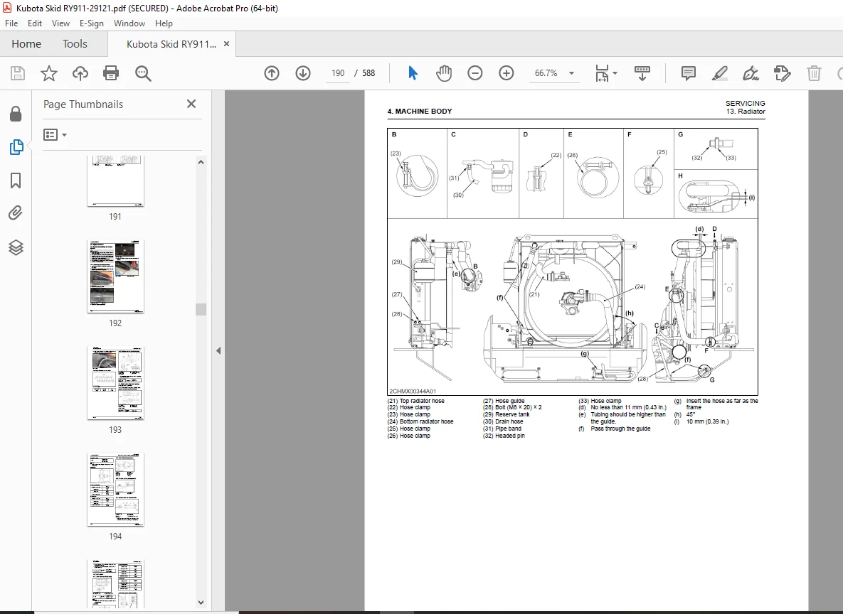
13 Radiator 4-31
131 Removing/Installing the radiator4-31
1311 Draining the coolant4-31
1312 Removing the battery4-31
1313 Installing the vacuum pump 4-32
1314 Removing the radiator 4-32
132 Radiator parts drawing 4-33
14 Rubber crawler 4-36
141 Removing/Installing the rubber crawler4-36
1411 Removing the rubber crawlers4-36
142 Rubber crawler parts drawing 4-37
15 Front idler, tension spring, and grease cylinder4-37
151 Front idler, tension spring, and grease cylinder parts drawing4-37
152 Front idler components 4-38
153 Tension spring components 4-38
154 Grease cylinder components 4-38
16 Track roller4-39
161 Track roller parts drawing4-39
162 Track roller components4-39
17 Rear idler 4-40
171 Rear idler parts drawing 4-40
172 Rear idler components 4-40
18 Pin, bushing4-41
181 Pins, bushing and shims list4-41
5 ENGINE
MECHANISM 5-1
1 Engine device layout 5-1
2 Engine specifications5-5
3 Engine dimensions 5-6
4 Engine performance curve 5-7
5 Engine control system 5-9
51 Engine control system general description 5-9
6 Common rail system 5-11
61 Common rail system general description 5-11
7 EGR system5-12
71 EGR system general description5-12
8 Supercharger system 5-13
81 Supercharger system general description5-13
9 DPF5-14
91 DPF general description5-14
92 DPF output limit and warning lamp 5-15
10 SCR system5-16
101 SCR system general description5-16
102 SCR output limit and warning lamp5-17
1021 Diesel Exhaust Fluid (DEF/AdBlue) level in SCR 5-17
1022 DEF/AdBlue concentration and quality 5-18
1023 SCR defrost control 5-19
1024 DEF/AdBlue pump (Tampering)5-20
1025 SCR system error (Tampering) 5-21
1026 SCR system error (Derating) 5-22
SERVICING 5-23
1 Intercooler5-23
11 Removing and installing the intercooler 5-23
12 Intercooler parts drawing5-25
2 Air cleaner 5-27
21 Air cleaner parts drawing 5-27
3 SCR muffler 5-28
31 Removing/Installing the SCR muffler 5-28
311 Removing and installing the intercooler5-28
312 Removing the SCR muffler 5-29
313 Installing the SCR muffler 5-30
32 SCR muffler pipe parts drawing 5-33
4 DPF muffler5-33
41 Removing/Installing the DPF muffler5-33
411 Removing and installing the intercooler5-33
412 Removing the SCR muffler 5-35
413 Removing the DPF muffler5-35
5 Engine 5-37
51 Removing/Installing the engine 5-37
511 Removing the cabin 5-37
512 Removing the battery5-37
513 Draining fuel5-38
514 Removing the radiator 5-38
515 Removal of the air cleaner5-39
516 Removing and installing the intercooler5-39
517 Removing the HST pump 5-41
518 Removing the SCR muffler 5-41
519 Removing the engine5-41
52 Engine parts drawing 5-44
521 Engine mount parts drawing 5-44
522 Oil separator parts drawing5-46
523 Muffler bracket parts drawing5-47
53 Removing/Installing the fuel tank 5-48
531 Cabin lock 5-48
532 Draining fuel5-48
533 Removing the step5-48
534 Removing the fuel tank 5-49
6 Fuel tank5-51
61 Fuel tank parts drawing5-51
62 Fuel pump parts drawing5-52
63 Fuel hose route 5-53
7 DEF/AdBlue tank 5-54
71 Removing the DEF/AdBlue tank 5-54
72 DEF/AdBlue hose routing5-56
8 DEF/AdBlue pump5-57
81 DEF/AdBlue pump parts drawing5-57
9 Coolant valve5-58
91 Coolant valve parts drawing5-58
911 Coolant valve parts drawing (Open cab model)5-58
912 Coolant valve parts drawing (Closed cab model) 5-58
6 HYDRAULIC SYSTEM
MECHANISM 6-1
1 Hydraulic equipment layout 6-1
2 HST pump 6-2
21 HST Pump specifications 6-2
22 HST Pump functions and structures 6-3
221 HST pump working principles 6-3
3 Piston pump6-5
31 Piston pump specifications6-5
32 Piston pump functions and structures 6-6
321 Piston pump working principles 6-6
322 Piston pump “Regulator” functions and structures6-6
323 Piston pump “Relief cut” function6-8
4 Gear pump6-9
41 Gear pump specifications6-9
5 Control valve6-10
51 Control valve specifications6-10
52 Control valve functions and structures 6-12
521 Control valve “Main relief valve” functions and structures 6-12
522 Control valve “LS relief valve” functions and structures6-12
523 Control valve “Overload relief valve” functions and structures 6-13
524 Control valve “Non-operation” hydraulic description6-14
525 Control valve “Lift arm down” hydraulic description 6-15
526 Control valve “Lift arm up” hydraulic description6-16
527 Control valve “Bucket leveling mechanism” hydraulic description 6-17
528 Control valve “Bucket operation” hydraulic description6-18
529 Control valve “AUX operation” hydraulic description 6-19
5210 Control valve “Load Sensing (flow control)” hydraulic description 6-20
5211 Control valve “Anti-Saturation” hydraulic description 6-23
5212 Control valve “Lift arm float operation” hydraulic description6-24
5213 Control valve “Hydraulic quick hitch” hydraulic description6-25
6 Pilot valve (Travel) 6-26
61 Pilot valve (Travel) specifications 6-26
62 Pilot valve (Travel) functions and structures 6-28
621 Pilot valve (Travel) working principles6-28
622 Pilot valve (Shuttle valve) functions 6-29
7 Pilot valve (Front operation) 6-29
71 Pilot valve (Front operation) specifications 6-29
72 Pilot valve (working equipment operation) functions and structures 6-32
721 Pilot valve (working equipment operation) working principles 6-32
8 Travel motor6-33
81 Travel motor specifications6-33
82 Travel motor functions and structures 6-34
821 Travel motor working principles 6-34
822 Travel motor “Reduction gear” working principles 6-34
823 Travel motor (Flushing) hydraulic description 6-35
824 Travel motor “Parking brake” working principles 6-36
825 Travel motor “Travel speed shift” working principles 6-36
83 Travel system 6-37
831 Travel system “Forward” hydraulic description 6-37
832 Travel system “Reverse” hydraulic description6-38
833 Travel system “Left swivel” hydraulic description 6-39
834 Travel system “right swivel” hydraulic description 6-40
835 Travel system “Pivot turn (forward left)” hydraulic description6-41
836 Travel system “Charge circuit” hydraulic description 6-42
837 Anti-stall function of the travel system 6-43
9 Hydraulic cylinder 6-44
91 Hydraulic cylinder specifications 6-44
10 Unload valve (Travel speed shift, parking brake, working equipment) 6-45
101 Unload valve (Travel speed shift, parking brake, work equipment) specifications 6-45
102 Unload valve (Travel speed shift, parking brake, work equipment) functions and structures 6-46
1021 Unload valve (Travel speed shift, parking brake, work equipment) working principles 6-46
11 Solenoid valve (Anti-stall, AUX) 6-47
111 Solenoid valve (Anti-stall, AUX) specifications 6-47
12 Solenoid valve (Hydraulic pressure quick hitch)6-48
121 Solenoid valve (Hydraulic pressure quick hitch) specifications6-48
SERVICING 6-49
1 Troubleshooting hydraulic6-49
11 Troubleshooting hydraulic for working equipment6-49
12 Troubleshooting hydraulic for traveling 6-51
2 Measuring this machine6-53
21 Hydraulic performance list6-53
22 Hydraulic operating time 6-53
221 Measuring the operating time for lift arm cylinder6-53
222 Measuring the operating time for bucket cylinder 6-53
223 Measuring the drift for working equipment6-54
224 Measuring the operating time for travel motor 6-54
225 Measuring the block performance for travel motor 6-54
226 Measuring the travel straightness for the travel motor6-55
3 HST pump 6-55
31 Measuring the HST pump 6-55
311 Measuring the flow rate for HST pump 6-55
312 Measuring travel relief pressure for HST pump 6-56
313 Adjusting the travel straightness for the HST pump 6-56
314 Adjusting swash plate neutral for HST pump6-57
32 Removing/Installing the HST pump6-57
321 Draining the hydraulic oil 6-58
322 Removing the cabin 6-58
323 Removing the step6-58
324 Removing the LS pump 6-60
325 Removing the HST pump 6-60
x SVL97-2
KiSC issued 09, 2021 A
33 Disassembling the HST pump6-61
331 Disassembling the shaft assembly 6-61
332 Disassembling the cylinder block6-63
333 Disassembling the relief valve 6-64
334 Disassembling the servo piston 6-64
34 Assembling the HST pump 6-66
341 Assembling the servo cylinder 6-66
342 Assembling the relief valve 6-68
343 Assembling the cylinder block (Engine side) 6-69
344 Assembling the shaft (Engine side) 6-71
345 Assembling the cylinder block (Pump side) 6-73
346 Assembling the the shaft (Pump side) 6-73
347 Assembling the adapter 6-75
35 HST pump components 6-76
36 Installing adapter layout for HST pump6-80
37 Pump coupling parts drawing6-81
4 Piston pump6-82
41 Measuring the piston pump6-82
411 Measuring the flow rate for piston pump6-82
42 Bleeding air from the piston pump 6-82
43 Removing/Installing the piston pump 6-83
431 Removing the cabin 6-83
432 Removing the step6-83
433 Installing the vacuum pump 6-85
434 Removing the piston pump 6-85
44 Disassembling the piston pump 6-85
441 Removing the gear pump 6-86
442 Removing the valve cover 6-86
443 Removing internal parts for piston pump 6-87
444 Disassembling the regulator for piston pump 6-88
45 Assembling the piston pump 6-89
451 Assembling the regulator for piston pump 6-89
452 Assembling internal parts for piston pump6-89
453 Assembling valve cover for piston pump 6-92
454 Assembling the gear pump 6-93
46 Piston pump components6-94
47 Installing adapter layout for piston pump 6-96
48 Servicing standards of piston pump 6-97
481 Measuring the piston clearance6-97
482 Measuring the play for shoe crimping section 6-97
483 Measuring shoe thickness 6-97
484 Measuring the length for cylinder spring6-98
485 Measuring the sinkage for spherical bushing 6-98
5 Control valve6-98
51 Measuring the control valve 6-98
511 Measuring the unload LS valve 6-98
512 Measuring the LS relief valve 6-99
513 Measuring the overload relief valve 6-99
514 Adjusting the flow dividing valve 6-100
52 Removing/Installing the control valve6-100
521 Removing the cabin 6-101
522 Installing the vacuum pump 6-101
523 Removing/Installing the control valve 6-101
53 Disassembling the control valve6-102
531 Removing the section for control valve6-102
532 Removing the flow divider section for the control valve6-104
533 Removing the relief valve for the control valve 6-105
534 Removing the float solenoid valve for the control valve6-107
SVL97-2 xi
KiSC issued 09, 2021 A
54 Assembling the control valve 6-108
541 Assembling the section for control valve 6-108
542 Assembling the flow divider section for control valve 6-110
543 Assembling the relief valve for the control valve 6-112
544 Assembling the float solenoid valve for the control valve 6-114
55 Control valve components 6-116
56 Installing adapter layout for control valve 6-119
6 Travel motor6-121
61 Removing/Installing the travel motor6-121
611 Removing/Installing the rubber crawler 6-121
612 Installing the vacuum pump 6-121
613 Removing the travel motor6-121
62 Disassembling the travel motor6-122
621 Disassembling the gear case for travel motor 6-122
622 Disassembling the hydraulic motor for the travel motor6-125
63 Assembling the travel motor6-128
631 Assembling the gear case for travel motor 6-128
632 Assembly of travel motor 6-133
64 Travel motor components6-139
65 Installing adapter layout for travel motor 6-141
7 Pilot valve 6-141
71 Measuring the piston pump6-141
711 Measuring pressure for pilot valve6-141
712 Measuring pressure for the pilot valve (Lift arm, bucket)6-142
72 Disassembling the pilot valve6-142
721 Removing the reducing valve 6-143
722 Disassembling the reducing valve 6-144
73 Assembling the pilot valve6-145
731 Assembling the reducing valve 6-145
732 Assembling the pilot valve 6-146
74 Pilot valve components 6-148
8 Lift arm cylinder 6-149
81 Disassembling/Installing the lift arm cylinder 6-149
811 Removing the lift arm6-149
812 Removing the battery6-149
813 Removing the lift arm cylinder 6-149
82 Disassembling the lift arm cylinder6-150
821 Disassembling the cylinder rod for lift arm cylinder 6-150
822 Disassembling the cylinder head for lift arm cylinder6-152
83 Assembling the lift arm cylinder 6-153
831 Assembling the cylinder head for lift arm cylinder 6-153
832 Assembling the cylinder rod for lift arm cylinder 6-154
84 Servicing standards for hydraulic cylinder6-157
841 Measuring the bend for cylinder rod 6-157
842 Measuring the wear for cylinder rod and cylinder head 6-158
843 Measuring the wear for the cylinder tube and piston wear ring 6-158
85 Lift arm cylinder components 6-159
9 Bucket cylinder 6-160
91 Removing/Installing the bucket cylinder6-160
911 Removing the bucket cylinder6-160
92 Bucket cylinder components 6-162
10 Hydraulic quick hitch cylinder 6-163
101 Removing/Installing the hydraulic quick hitch cylinder 6-163
1011 Removing the quick hitch cylinder 6-163
102 Hydraulic quick hitch cylinder components 6-163
11 Unload valve 6-164
111 Removing/Installing the unload valve 6-164
1111 Installing the vacuum pump 6-164
xii SVL97-2
KiSC issued 09, 2021 A
1112 Cabin lock 6-164
1113 Removing the unload valve6-164
112 Installing adapter layout for unload valve 6-166
12 Solenoid valve (Anti-stall, AUX)6-167
121 Disassembly/Assembly of solenoid valves (Anti-stall, AUX) 6-167
1211 Installing the vacuum pump 6-167
1212 Cabin lock 6-167
1213 Removal of solenoid valve (Anti-stall, AUX) 6-167
122 Installing adapter layout for solenoid valve (Anti-stall, AUX)6-168
13 Solenoid valve (Hydraulic pressure quick hitch)6-168
131 Installing adapter layout for solenoid valve (Hydraulic quick hitch)6-168
14 Hydraulic oil tank 6-168
141 Removing/Installing the hydraulic oil tank 6-168
1411 Draining the hydraulic oil 6-168
1412 Cabin lock 6-169
1413 Removing the step6-169
1414 Removing the LS pump 6-171
1415 Removing the hydraulic oil tank6-171
142 Hydraulic oil tank components 6-173
143 Installing adapter layout for hydraulic oil tank 6-175
15 Hydraulic hoses 6-176
151 Total length for hydraulic hoses6-176
152 Hydraulic hose fittings 6-176
153 Hose route6-177
1531 Piston pump6-177
1532 HST pump, HST filter6-179
1533 Control valve6-181
1534 Bucket cylinder 6-184
1535 Unload valve 6-185
1536 AUX solenoid valve6-187
1537 Relay, pilot valve 6-189
1538 Quick hitch model 6-191
7 ELECTRICAL SYSTEM
MECHANISM 7-1
1 Electrical device7-1
11 Layout of electrical device7-1
2 Meter panel7-4
21 Meter panel display 7-4
22 Lamps 7-5
23 Buzzer 7-5
24 Meter panel functions7-6
25 Normal mode7-6
251 Normal mode display 7-6
26 User settings mode 7-7
261 AUX flow rate setting in user setting mode7-7
27 Service mode 7-8
271 Service mode settings list 7-8
SERVICING 7-9
1 Troubleshooting electrical issues7-9
11 Troubleshooting electrical 7-9
2 Troubleshooting errors7-9
21 Error warning list 7-9
22 Engine error warning list 7-11
23 E:001 CAN communication error 7-13
231 Checking on the meter panel for E:001 CAN communication error 7-13
232 Checking on the meter panel for E:001 CAN communication error 7-13
233 Checking with circuit tester for E:001 CAN communication error 7-14
SVL97-2 xiii
KiSC issued 09, 2021 A
24 E:005 High hydraulic oil temperature 7-14
241 Checking on the meter panel for E:005 high hydraulic oil temperature 7-14
242 Checking devices for E:005 high hydraulic oil temperature7-14
25 E:008 Fuel sensor error 7-15
251 Checking on the meter panel for E:008 fuel sensor error 7-15
252 Checking devices for E:008 fuel sensor error7-15
253 Checking circuit tester for E:008 fuel sensor error7-16
26 E:009 Accelerator dial sensor (Break or short) 7-17
261 Checking on the meter panel for E:009 accelerator sensor error 7-17
262 Checking devices for E:009 accelerator sensor error7-18
263 Checking with circuit tester for E:009 Accelerator sensor error 7-18
27 E:010 Travel speed shift solenoid error7-19
271 Checking on the meter panel for E:010 travel speed shift solenoid error 7-19
272 Checking devices for E:010 travel speed shift solenoid error7-20
273 Checking with circuit tester for E:010 travel speed shift solenoid error 7-20
28 E:011 Parking brake solenoid error 7-22
281 Checking on the meter panel for E:011 parking brake solenoid error 7-22
282 Checking devices for E:011 parking brake solenoid error7-22
283 Checking with circuit tester for E:011 parking brake solenoid error 7-23
29 E:012 Float solenoid error7-24
291 Checking on the meter panel for E:012 float solenoid error 7-24
292 Checking devices for E:012 float solenoid error 7-25
293 Checking with circuit tester for E:012 float solenoid error7-25
210 E:013 Hydraulic lock release solenoid error7-27
2101 Checking on the meter panel for E:013 hydraulic lock release solenoid error 7-27
2102 Checking devices for E:013 hydraulic lock release solenoid error 7-27
2103 Checking with circuit tester for E:013 hydraulic lock release solenoid error 7-28
211 E:014 Low hydraulic oil temperature error7-30
212 Checking on the meter panel for E:014 low hydraulic oil temperature 7-30
213 Checking devices for E:014 low hydraulic oil temperature error 7-30
214 Checking with circuit tester for E:014 low hydraulic oil temperature error 7-31
215 E:015 Hydraulic hitch solenoid error 7-32
2151 Checking on the meter panel for E:015 hydraulic hitch solenoid error 7-32
2152 Checking devices for E:015 hydraulic hitch solenoid error 7-32
2153 Checking with circuit tester for E:015 hydraulic hitch solenoid error 7-33
216 E:016 AUX knob-switch error7-35
2161 Checking on the meter panel for E:016 AUX knob-switch error 7-35
2162 Checking devices for E:016 AUX knob-switch error 7-35
2163 Checking with the circuit tester for E:016 AUX knob-switch error 7-35
217 E:018 AUX right solenoid error 7-36
2171 Checking on the meter panel for E:018 AUX right solenoid error 7-36
2172 Checking devices for E:018 AUX right solenoid error7-37
2173 Checking with circuit tester for E:018 AUX right solenoid error 7-37
218 E:019 AUX left solenoid error7-38
2181 Checking on the meter panel for E:019 AUX left solenoid error 7-38
2182 Checking devices for E:019 AUX left solenoid error7-39
2183 Checking with circuit tester for E:019 AUX left solenoid error 7-39
219 E:020 Anti-stall solenoid error 7-40
2191 Checking on the meter panel for E:020 Anti-stall solenoid error 7-40
2192 Checking devices for E:020 Anti-stall solenoid error 7-41
2193 Checking with circuit tester for E:020 Anti-stall solenoid error 7-41
220 E:021 5 V error7-42
2201 Checking on the meter panel for E:021 5 V error 7-42
2202 Checking devices for E:021 5 V error 7-42
2203 Checking external 5 V short with a circuit tester7-44
221 E:023 Overvoltage 7-47
2211 Checking on the meter panel for E:023 overvoltage7-47
2212 Checking devices for E:023 overvoltage 7-47
xiv SVL97-2
KiSC issued 09, 2021 A
2213 Checking with circuit tester for E:023 overvoltage7-47
222 E:024 Hydraulic oil temperature sensor error 7-48
2221 Checking on the meter panel for E:024 hydraulic oil temperature sensor error 7-48
2222 Checking devices for E:024 hydraulic oil temperature sensor error 7-48
2223 Checking with circuit tester for E:024 hydraulic oil temperature sensor error 7-48
223 E:026 CRS CAN communication error7-50
2231 Checking on the meter panel for E:026 CRS CAN communication error 7-50
2232 Checking devices for E:026 CRS CAN communication error 7-50
2233 Checking with circuit tester for E:026 CRS CAN communication error 7-52
224 E:027 ACU CAN communication error7-52
2241 Check on the meter panel for E:027 ACU CAN communication error 7-52
2242 Checking devices for E:027 ACU CAN communication error 7-53
2243 Check with circuit tester for E:027 ACU CAN communication error 7-55
225 E:028 Foot accelerator sensor error 7-55
2251 Checking on the meter panel for E:028 foot accelerator sensor error 7-55
2252 Checking devices for E:028 foot accelerator sensor error7-56
2253 Checking with circuit tester for E:028 foot accelerator sensor error 7-56
226 E:9116 Engine overheating 7-58
2261 Checking on the meter panel for E:9116 Engine overheating 7-58
2262 Checking devices for E:9116 engine overheating7-58
227 E:9118 Engine oil pressure error7-58
2271 Checking on the meter panel for E:9118 engine oil pressure error 7-58
2272 Checking devices for E:9118 engine oil pressure error 7-59
2273 Checking with circuit tester for E:9118 engine oil pressure error 7-60
228 E:9119 Battery charging error 7-61
2281 Checking on the meter panel for E:9119 battery charging error 7-61
2282 Checking devices for E:9119 battery charging error 7-61
2283 Checking with circuit tester for E:9119 battery charging error 7-61
229 E:9120 Water separator error7-62
2291 Checking on the meter panel for E:9120 water separator error 7-62
2292 Checking devices for E:9120 water separator error 7-62
2293 Checking with circuit tester for E:9120 water separator error 7-63
230 E:9126 CCV pressure error7-63
2301 Checking on the meter panel for E:9126 CCV pressure error 7-63
2302 Checking devices for E:9126 CCV pressure error7-63
2303 Checking with circuit tester for E:9126 CCV pressure error 7-64
231 E:9127 Continuous CCV pressure error 7-66
2311 Checking on the meter panel for E:9127 continuous CCV pressure error 7-66
3 Meter panel settings 7-66
31 Meter panel switches operation 7-66
32 AUX flow rate setting7-67
33 Service mode operations 7-67
34 No-01 Tester mode7-68
35 No-02 AUX knob setting7-71
36 No-03 AUX start-up point setting 7-71
37 No-04 AUX current fine setting 7-72
38 No-05 HST start-up point setting7-73
39 No-07 Accelerator pedal/dial setting 7-74
310 No-09 Read error history7-74
311 No-10 Clear error history 7-74
312 No-11 Read all error history 7-75
313 No-12 AUX flow rate adjustment7-75
8 AIR CONDITIONING AND HEATER SYSTEM
MECHANISM 8-1
1 Air conditioning system8-1
11 Air conditioning equipments layout 8-1
12 Air conditioning system general description8-3
SVL97-2 xv
KiSC issued 09, 2021 A
2 Compressor 8-4
21 Compressor specifications 8-4
22 Compressor functions and structures 8-5
23 Magnetic clutch functions and structures 8-5
24 Safety valve functions and structures 8-6
25 Temperature sensor functions and structures 8-6
26 Compressor oil functions and structures8-6
3 Air conditioning unit 8-7
31 Air conditioning specifications 8-7
32 Evaporator functions and structures 8-8
33 Heater core functions and structures 8-8
34 Blower motor functions and structures8-8
35 Blower resistor functions and structures 8-9
36 Expansion valve functions and structures8-9
37 Fin thermistor functions and structures 8-10
38 Hot water valve functions and structures 8-10
4 Condenser 8-11
41 Condenser specifications 8-11
42 Condenser functions and structures 8-11
5 Receiver 8-11
51 Receiver specifications 8-11
52 Receiver functions and structures8-12
6 Pressure switch 8-12
61 Pressure switch specifications 8-12
62 Pressure switch functions and structures8-13
SERVICING 8-15
1 Troubleshooting 8-15
11 Troubleshooting the air conditioning system 8-15
12 Troubleshooting the compressor8-17
2 Fuse8-17
21 Checking the fuses8-17
3 Relay 8-18
31 Checking the relays8-18
4 Air conditioning control panel 8-19
41 Checking the air conditioning control panel 8-19
5 Compressor 8-20
51 Measuring and checking the compressor 8-20
52 Removing/Installing the compressor 8-21
53 Oil amount in the compressor 8-22
6 Air conditioner unit8-23
61 Measuring and checking the air conditioning unit 8-23
611 Measuring and checking the blower motor 8-23
612 Measuring and checking the blower resistor 8-23
62 Removing/Installing the air conditioning unit8-24
63 Air conditioning unit parts drawing 8-26
7 Condenser and receiver 8-26
71 Measuring and checking the condenser 8-26
711 Measuring and checking the condenser fan motor8-26
72 Removing/Installing the condenser and the receiver 8-27
8 Air conditioning hose 8-29
81 Removing/Installing the air conditioning hose8-29
9 Heater hose 8-30
91 Removing/Installing the heater hose8-30
DESCRIPTION:
Kubota SVL97-2 Compact Track Loader Workshop Manual – PDF DOWNLOAD
TO THE READER:
This workshop manual provides safety information for service activity, general information such as specifications and dimensions of the machine, mechanisms and structure descriptions of the machine, and service procedures. Safety
This section contains safety service descriptions and safety label information.
General:
This section contains general instructions, tightening torques, general machine information and special tools. Maintenance
This section contains information for the recommended oil and general maintenance procedures.
Each section basically consists of mechanism and servicing.
Mechanism:
Mechanism part contains information and explanations for the structure, functions, and specifications of the machine or component parts. This part should be comprehended before proceeding with troubleshooting, disassembling. assembling, and servicing works.
Servicing:
Servicing part contains information and procedures for maintenance, troubleshooting and repair works. The reader should follow these instructions in order to satisfy any servicing work safely, correctly and quickly.
In this WSM, service specifications and service limits are defined as followings.
Service specifications:
Specification which corresponds to new machine’s ex-factory. It is based on quality standard, drawings, or actual measurements conducted by Kubota. This value is used to determine whether there is a problem with the machine in the event of a troubleshooting. However, it is necessary to consider degradation due to wear, based on the operating time of the machine, application or maintenance condition.
Service limits:
Service limit is a value corresponding to the recommended performance limit by taking long term-use wear into account. When the service limit is reached, the machine is required to have proper repair, overhaul or replacement in order to keep safe and adequate performance.
All of the illustrations, photographs, specifications, and other information in this manual were created based on the latest model at the time of publication.
The parts names used in this manual are unified into names representing the functions of the parts. Therefore, it does not necessarily correspond to the names used in other materials (parts list, operators manual etc.) and the name on the label/identification plates on the product.
Kubota reserves the right to change all information at any time without notice.
G.B 19/02/25