Komatsu Wheel Loader WA320-6 WA320PZ-6 Shop Manual SEN03911-11 PDF
$37.95
Komatsu Wheel Loader WA320-6 WA320PZ-6 Shop Manual SEN03911-11 – PDF DOWNLOAD
SERIAL NUMBERS WA320- 70001
WA320PZ-70001 and up
Description
Komatsu Wheel Loader WA320-6 WA320PZ-6 Shop Manual SEN03911-11 – PDF DOWNLOAD
FILE DETAILS:
Komatsu Wheel Loader WA320-6 WA320PZ-6 Shop Manual SEN03911-11 – PDF DOWNLOAD
Language : English
Pages :1340
Downloadable : Yes
File Type : PDF
IMAGES PREVIEW OF THE MANUAL:
DESCRIPTION:
Komatsu Wheel Loader WA320-6 WA320PZ-6 Shop Manual SEN03911-11 – PDF DOWNLOAD
SERIAL NUMBERS WA320- 70001
WA320PZ-70001 and up
1. General precautions
Mistakes in operation are extremely dangerous. Read the Operation and Maintenance Manual carefully before operating the machine. In addition, read this manual and understand its contents before starting the work.
TABLE OF CONTENTS:
Komatsu Wheel Loader WA320-6 WA320PZ-6 Shop Manual SEN03911-11 – PDF DOWNLOAD
SERIAL NUMBERS WA320- 70001
WA320PZ-70001 and up
CIVER 1
00 Index and foreword 3
100 Index 3
Composition of shop manual 4
Table of contents 6
200 Foreword and general information 17
Safety notice 18
How to read the shop manual 23
Explanation of terms for maintenance standard 25
Handling of electric equipment and hydraulic component 27
Handling of connectors newly used for engines 36
How to read electric wire code 39
Precautions when carrying out operation 42
Method of disassembling and connecting push-pull type coupler 45
Standard tightening torque table 48
Conversion table 52
01 Specification 59
100 Specification and technical data 59
Specification dimension drawing 61
Specifications 62
Weight table 66
Table of fuel, coolant and lubricants 68
10 Structure, function and maintenance standard 71
100 Engine and cooling system 71
Engine mount and transfer mount 72
Damper 73
Cooling system 74
Cooling system hydraulic piping diagram 75
Cooling fan motor 77
200 Power train 87
Power train 89
Power train system diagram 90
Drive shaft 92
HST hydraulic piping diagram 93
HST pump 94
HST motor 102
Transfer 108
Clutch solenoid valve 119
Axle 120
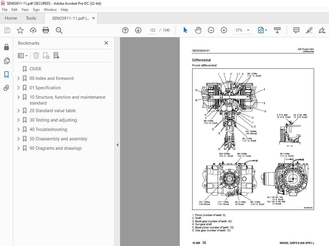
Differential 122
Torque proportioning differential 127
Limited slip differential 130
Final drive 134
300 Steering system 139
Steering piping diagram 141
Steering column 142
Priority valve 143
Orbit-roll valve 146
Cushion valve 154
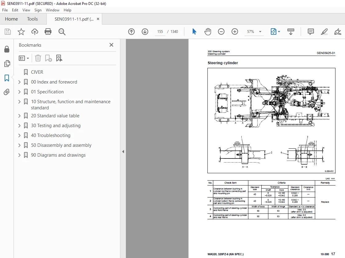
Steering cylinder 155
Emergency steering piping diagram 157
Emergency steering valve 158
Steering relief valve 161
400 Brake system 163
Brake piping diagram 165
Charge valve 166
Brake valve 170
Inching valve 174
Accumulator (for brake) 175
Slack adjuster 176
Brake 178
Parking brake control 183
Parking brake 184
500 Undercarriage and frame 187
Axle mount and center hinge pin 188
Tires 197
600 Hydraulic system 199
Work equipment hydraulic piping diagram 200
Work equipment control lever linkage 204
Hydraulic tank 208
4-gear pump 210
Work equipment control valve 212
Cut-off valve 238
PPC valve 241
Lock valve 256
Accumulator (for PPC circuit) 257
ECSS valve 259
Accumulator (for ECSS) 261
700 Work equipment 263
Work equipment linkage 264
Bucket 268
Bucket positioner and boom kick-out 272
Work equipment cylinder 284
800 Cab and its attachments 287
Cab 289
Air conditioner 290
910 Electrical system, Part 1 303
Machine monitor system 304
Machine monitor 308
920 Electrical system, Part 2 331
Electrical system (HST controller system) 332
HST controller 348
ECSS system 350
KOMTRAX system 352
Engine starting circuit 354
Engine stopping circuit 356
Preheating circuit 357
Engine output derating function 358
Automatic warm-up function 358
Parking brake circuit 360
Coupler plunger control system 362
Multi-function knob 363
Max traction switch 364
Sensor 365
20 Standard value table 373
100 Standard service value table 373
Standard service value table for engine 374
Standard service value table for chassis 375
30 Testing and adjusting 383
110 Testing and adjusting, Part 1 383
Tools for testing, adjusting, and troubleshooting 385
Measuring engine speed 390
Measuring exhaust gas color 392
Adjusting valve clearance 394
Measuring compression pressure 396
Measuring blow-by pressure 399
Measuring engine oil pressure 400
Measuring intake air (boost) pressure 401
Handling fuel system equipment 403
Releasing residual pressure in fuel system 403
Measuring fuel pressure 404
Measuring fuel return rate and leakage 406
Bleeding air from fuel circuit 410
Checking leakage in fuel system 411
Handling cylinder cut-out mode operation 412
Handling no-injection cranking operation 412
Handling controller voltage circuit 413
Check of muffler and muffler stack for looseness and damage 413
Check of muffler function 414
Check of installed condition of cylinder head and manifolds 414
Check of engine piping for damage and looseness 415
Testing and adjusting air conditioner compressor belt tension 415
Replacing alternator belt 416
120 Testing and adjusting, Part 2 419
Checking operating force of accelerator pedal 421
Checking directional lever 422
Testing and adjusting HST oil pressure 423
Testing clutch control pressure 427
Testing and adjusting steering wheel 428
Testing and adjusting steering oil pressure 430
Bleeding air from steering circuit 432
Testing hydraulic fan 433
Measuring brake pedal 435
Testing and adjusting brake pedal linkage 436
Measuring brake performance 437
Testing and adjusting accumulator charge pressure 438
Testing wheel brake oil pressure 440
Testing wear of brake disc 443
Bleeding air from wheel brake circuit 444
Releasing residual pressure in brake accumulator circuit 445
Testing parking brake performance 446
Testing and adjusting parking brake control cable 447
Measuring and adjusting work equipment control lever 448
Testing and adjusting worke quipment hydraulic pressure 449
Testing work equipment PPC oil pressure 450
Bleeding air from hydraulic circuit 452
Releasing remaining pressure in hydraulic circuit 453
Testing and adjusting bucket positioner 454
Testing and adjusting of boom kick-out switch 455
Checking proximity switch operation pilot lamp 456
Procedure for testing diodes 457
Preparation work for troubleshooting for electric system 458
Starting KOMTRAX terminal operations 462
Indicator lamps of KOMTRAX terminal 466
130 Testing and adjusting, Part 3 471
Adjusting machine monitor 472
Adjusting replaced, reassembled or added sensor, controller, etc with machine monitor 473
Special functions of machine monitor (EMMS) 475
Pm clinic inspection chart 530
40 Troubleshooting 533
100 Failure code table and fuse locations 533
Failure codes table 534
Fuse locations 540
200 General information on troubleshooting 545
Points to remember when troubleshooting 546
Sequence of events in troubleshooting 547
Testing before troubleshooting 548
Classification and procedures of troubleshooting 549
Information contained in troubleshooting table 552
Connection table for connector pin numbers 554
T- branch box and T- branch adapter table 590
310 Troubleshooting by failure code (Display of code), Part 1 595
Failure code [2G40ZG] Brake: Oil pressure reduction 596
Failure code [6091NX] HST filter: Clogging 598
Failure code [989FN1] Travel speed: Overrun alarm 600
Failure code [AA1ANX] Air cleaner: Clogging 602
Failure code [AB00L6] Alternator R system: Hot short 604
Failure code [AB00MA] Alternator R system: Ground fault/Disconnection/Low charge voltage 606
Failure code [B@BAZG] Engine: Oil pressure reduction 608
Failure code [B@BAZK] Engine oil: Low level 609
Failure code [B@BCNS] Engine: Overheat 610
Failure code [B@BCZK] Engine: Low coolant level 612
Failure code [B@C6NS] Front brake: High oil temperature 614
Failure code [B@CRNS] HST: High oil temperature 615
320 Troubleshooting by failure code (Display of code), Part 2 617
Failure code [CA111] Abnormality in engine controller 619
Failure code [CA115] Engine Ne or Bkup speed sensor error 620
Failure code [CA122] Charge pressure sensor high error 622
Failure code [CA123] Charge pressure sensor low error 624
Failure code [CA131] Throttle sensor high error 626
Failure code [CA132] Throttle sensor low error 628
Failure code [CA144] Coolant sensor high error 630
Failure code [CA145] Coolant sensor low error 632
Failure code [CA153] Charge temperature sensor high error 634
Failure code [CA154] Charge temperature sensor low error 636
Failure code [CA155] Derating of speed by abnormally high charge temperature 638
Failure code [CA187] Sensor power supply 2 low error 640
Failure code [CA221] Atmospheric pressure sensor high error 642
Failure code [CA222] Atmospheric sensor low error 644
Failure code [CA227] Sensor power supply 2 high error 646
Failure code [CA234] Engine overspeed 647
Failure code [CA238] Ne speed sensor power supply error 648
Failure code [CA271] IMV (IMA) Short circuit 649
Failure code [CA272] IMV (IMA) Disconnection 650
Failure code [CA322] Injector #1 open/short error 652
Failure code [CA323] Injector #5 open/short error 654
Failure code [CA324] Injector #3 open/short error 656
Failure code [CA325] Injector #6 open/short error 658
Failure code [CA331] Injector #2 open/short error 660
Failure code [CA332] Injector #4 open/short error 662
Failure code [CA342] Calibration code inconsistency 664
Failure code [CA351] Injectors drive circuit error 666
Failure code [CA352] Sensor power supply 1 low error 668
Failure code [CA386] Sensor power supply 1 high error 670
330 Troubleshooting by failure code (Display of code), Part 3 673
Failure code [CA428] Abnormally high level in water sensor 676
Failure code [CA429] Abnormally low level in water sensor 678
Failure code [CA431] Idle validation switch error 680
Failure code [CA432] Idle validation action error 684
Failure code [CA435] Engine oil pressure switch error 688
Failure code [CA441] Battery voltage low error 689
Failure code [CA442] Battery voltage high error 692
Failure code [CA449] Common rail pressure high error 2 694
Failure code [CA451] Common rail pressure sensor high error 696
Failure code [CA452] Common rail pressure sensor low error 698
Failure code [CA488] Derating of torque by abnormally high charge temperature 700
Failure code [CA553] Common rail pressure high error 1 701
Failure code [CA559] Supply pump pressure very low error 702
Failure code [CA689] Engine Ne speed sensor error 704
Failure code [CA731] Engine Bkup speed sensor phase error 706
Failure code [CA757] All continuous data lost error 707
Failure code [CA778] Engine Bkup speed sensor error 710
Failure code [CA1633] KOMNET datalink timeout error 712
Failure code [CA2185] Throttle sensor supply voltage high error 716
Failure code [CA2186] Throttle sensor power supply low error 718
Failure code [CA2249] Supply pump pressure very low error 2 720
Failure code [CA2311] Abnormality in IMV (IMA) solenoid 722
Failure code [CA2555] Intake heater relay disconnection error 724
Failure code [CA2556] Intake heater relay short circuit error 726
340 Troubleshooting by failure code (Display of code), Part 4 729
Failure code [D160KY] Backup alarm/lamp relay 1 circuit: Hot short 730
Failure code [D192KY] ECSS solenoid relay: Hot short 732
Failure code [D1B0KA] HST safety relay: Disconnection 734
Failure code [D1B0KB] HST safety relay: Ground fault 736
Failure code [D1B0KY] HST safety relay: Hot short 738
Failure code [D5ZHL6] IGN C system: Ground fault/Disconnection 740
Failure code [DAF3KK] UNSW power supply: Ground fault/Disconnection 742
Failure code [DAFRKR] Machine monitor CAN-NET Signal: Disconnection 744
Failure code [DAJ0KK] HST controller power supply: Low voltage 748
Failure code [DAJ0KT] HST controller memory (EEPROM): Abnormality 750
Failure code [DAJ1L4] HST controller main power line: Disconnection/Ground fault 752
Failure code [DAJ1L6] HST controller main power line: Hot short 754
Failure code [DAJ2KK] Controller solenoid power supply: Low voltage 756
Failure code [DAJ2L3] HST controller load power supply holding line: Hot short in wiring harness 758
Failure code [DAJ2L4] HST controller load power supply holding line: Disconnection/Ground fault 760
Failure code [DAJ5KX] Sensor 5V power supply: Out of output range 762
Failure code [DAJ9KQ] HST controller model selection: Disagreement of model selection signals 764
Failure code [DAJRKR] HST controller CAN-NET signal: Disconnection 765
Failure code [DAJRMA] HST controller: Disagreement in option selection 771
350 Troubleshooting by failure code (Display of code), Part 5 773
Failure code [DB2RKR] Engine controller CAN-NET: Disconnection in signal line 774
Failure code [DD1NL4] Fan automatic reverse switch signal: Abnormality 780
Failure code [DD1NLD] Fan reverse switch signal: Abnormality 782
Failure code [DDB6KA] Parking brake reminder signal: Disconnection/Hot short 784
Failure code [DDB6KB] Parking brake indicator signal: Ground fault 786
Failure code [DDB6KZ] Parking brake switch (bottom switch) or parking brake reminder switch (intermediate switch): Trouble 788
Failure code [DDB6L0] Parking brake reminder signal: Ground fault 790
Failure code [DDB6L4] Parking brake indicator signal: Disconnection/Hot short 792
Failure code [DDD7KX] Travel speed control dial signal: Disconnection/Ground fault 794
Failure code [DDD7KY] Travel speed control dial signal: Hot short 796
Failure code [DDE5MA] Emergency steering operation switch: Disconnection 798
Failure code [DDK3KA] Directional selector switch: Disconnection/Hot short 800
Failure code [DDK3KB] Directional selector switch: Ground fault 802
Failure code [DDK6KA] FNR lever: Disconnection/Ground fault 804
Failure code [DDK6KY] FNR lever: Hot short 808
Failure code [DDS5L6] Steering: Low oil pressure (Operation of emergency steering) 810
360 Troubleshooting by failure code (Display of code), Part 6 813
Failure code [DF10KA] Travel speed range selector switch: Disconnection/Ground fault 814
Failure code [DF10KB] Travel speed range selector switch: Hot short 818
Failure code [DGH1KX] HST oil temperature sensor: Ground fault 820
Failure code [DGR2KB] Brake oil temperature sensor: Ground fault 821
Failure code [DGR2KZ] Brake oil temperature sensor: Disconnection/Hot short 822
Failure code [DHH1KX] HST oil pressure sensor: Disconnection/Ground fault 824
Failure code [DHH1KY] HST oil pressure sensor: Hot short 826
Failure code [DHTCL6] HST filter clogging sensor: Functional defect 828
Failure code [DJF1KA] Fuel level sensor: Disconnection/Hot short 830
Failure code [DLT3KX] Travel speed sensor B: Abnormality 832
Failure code [DLT4KX] Travel speed sensor A: Abnormality 836
Failure code [DLT4LC] Travel speed sensor A & B: Abnormality 838
Failure code [DV00KY] Alarm buzzer: Hot short 840
Failure code [DW26KA] Motor 2 solenoid: Disconnection/Ground fault 842
Failure code [DW26KY] Motor 2 solenoid: Hot short 844
Failure code [DW7BKY] Fan reverse solenoid circuit: Hot short 846
Failure code [DW7BKZ] Fan reverse solenoid circuit: Disconnection/Ground fault 848
370 Troubleshooting by failure code (Display of code), Part 7 851
Failure code [DX16KA] Fan EPC solenoid: Disconnection 852
Failure code [DX16KB] Fan EPC solenoid: Ground fault 853
Failure code [DX16KY] Fan EPC solenoid: Hot short 854
Failure code [DX19KA] Motor 1 solenoid: Disconnection 856
Failure code [DX19KB] Motor 1 solenoid: Ground fault 858
Failure code [DX19KY] Motor 1 solenoid: Hot short 860
Failure code [DX20KA] Clutch EPC solenoid: Disconnection 862
Failure code [DX20KB] Clutch EPC solenoid: Ground fault 864
Failure code [DX20KY] Clutch EPC solenoid: Hot short 866
Failure code [DXH7KB] Reverse solenoid: Ground fault 868
Failure code [DXH7KZ] Reverse solenoid: Disconnection/Hot short 870
Failure code [DXH8KB] Forward solenoid: Ground fault 872
Failure code [DXH8KZ] Forward solenoid: Disconnection/Hot short 874
Failure code [J141N1] Steering pump: Overrun alarm 876
Failure code [M100N1] HST pump: Overrun alarm 876
Failure code [M400N1] Motor 1: Overrun alarm 877
400 Troubleshooting of electrical system (E-mode) 879
E-1 Engine does not start 882
E-2 Preheater does not operate normally 890
E-3 Travel speed is low or high 894
E-4 ECSS does not operate 900
E-5 ECSS keeps operating 903
E-6 Defective boom kick-out function and cancellation 906
E-7 Defective bucket positioner function and cancellation 910
E-8 Defective lift arm FLOATING holding function and cancellation 914
E-9 Travel direction selection system does not function 918
E-10 Fan does not reverse 922
E-11 Fan keeps rotating in reverse 926
E-12 Wiper does not operate 928
E-13 Windshield washer does not operate 932
E-14 Headlamp, clearance lamp and tail lamp do not light up or go off 936
E-15 Working lamp does not light up or go off 944
E-16 Turn signal lamp and hazard lamp do not light up or go off 950
E-17 Brake lamp does not light or it keeps lighting up 956
E-18 Backup lamp does not light or it keeps lighting up 958
E-19 Backup alarm does not sound or it keeps sounding 961
E-20 Horn does not sound or it keeps sounding 964
E-21 Alarm buzzer does not sound or it keeps sounding 966
E-22 Air conditioner does not operate or stop 968
E-23 The KOMTRAX system does not work properly 972
500 Troubleshooting of hydraulic and mechanical system (H-mode) 975
Method of using troubleshooting chart 977
Failure code and cause table 980
H-1 The machine does not start 982
H-2 The travel speed is slow 983
H-3 The traction force is weak 984
H-4 Engine stalls when traveling or engine speed drops excessively 985
H-5 Shift range is not shifted 986
H-6 The steering wheel does not turn 987
H-7 The steering wheel is heavy 988
H-8 Steering wheel shakes or jerks 989
H-9 Machine deviates naturally to one side when traveling 989
H-10 The brake does not work or does not work well 990
H-11 The brake is not released or is dragged 991
H-12 The lift arm does not rise or lower 992
H-13 The lift arm moves slowly or the lift arm rising force is insufficient 993
H-14 When rising, the lift arm comes to move slowly at specific height 994
H-15 The lift arm cylinder cannot hold down the bucket (The bucket rises in the air) 994
H-16 Hydraulic drifts of the lift arm occur often 994
H-17 The lift arm wobbles during operation 994
H-18 When the control lever is switched from “HOLD” to “RAISE,” the lift arm falls temporarily 995
H-19 The bucket does not tilt back 996
H-20 The bucket moves slowly or the tilting-back force is insufficient 997
H-21 The bucket comes to operate slowly in the midst of tilting-back 998
H-22 The bucket cylinder cannot hold down the bucket 998
H-23 Hydraulic drifts of the bucket occur often 998
H-24 The bucket wobbles during travel with load (The work equipment valve is set to “HOLD”) 998
H-25 When the control lever is switched from “HOLD” to “TILT,” the bucket falls temporarily 999
H-26 The control levers of the lift arm and bucket do not move smoothly and heavy 999
H-27 The ECSS does not operate and machine pitches and bounces1000
H-28 Fan revolution is abnormal (Fan sound/vibration is abnormally large or engine overheats)1001
600 Troubleshooting of engine (S-mode)1003
Method of using troubleshooting charts1004
S-1 Starting performance is poor1008
S-2 Engine does not start1010
S-3 Engine does not pick up smoothly1013
S-4 Engine stops during operations1014
S-5 Engine does not rotate smoothly1015
S-6 Engine lacks output (or lacks power)1016
S-7 Exhaust smoke is black (incomplete combustion)1017
S-8 Oil consumption is excessive (or exhaust smoke is blue)1018
S-9 Oil becomes contaminated quickly1019
S-10 Fuel consumption is excessive1020
S-11 Oil is in coolant (or coolant spurts back or coolant level goes down)1021
S-12 Oil pressure drops1022
S-13 Oil level rises (Entry of coolant or fuel)1023
S-14 Coolant temperature becomes too high (overheating)1024
S-15 Abnormal noise is made1025
S-16 Vibration is excessive1026
50 Disassembly and assembly1029
100 General information on disassembly and assembly1029
How to read this manual1030
Coating materials list1032
Special tool list1035
Sketches of special tools1039
200 Engine and cooling system1047
Removal and installation of fuel supply pump assembly1048
Removal and installation of fuel injector assembly1050
Removal and installation of cylinder head assembly1058
Removal and installation of engine hood assembly1071
Removal and installation of radiator1074
Removal and installation of air aftercooler1077
Removal and installation of hydraulic oil cooler assembly1079
Removal and installation of engine assembly1081
Removal and installation of engine front oil seal assembly1087
Removal and installation of engine rear oil seal assembly1090
Removal and installation of cooling fan and fan motor assembly1093
Removal and installation of fuel tank assembly1096
310 Power train, Part 11099
Removal and installation of transfer1100
Disassembly and assembly of transfer assembly1103
Removal and installation of parking brake assembly1123
Disassembly and assembly of parking brake assembly1124
320 Power train, Part 21131
Removal and installation of front axle assembly1132
Removal and installation of rear axle assembly1134
Disassembly and assembly of axle housing assembly1137
Disassembly and assembly of differential assembly1149
400 Undercarriage and frame1173
Removal and installation of center hinge pin1174
Removal and installation of counterweight1186
500 Hydraulic system1189
Removal and installation of HST pump and 4-gear pump assembly1190
Disassembly and assembly of HST pump assembly1193
Removal and installation of HST motor 1 assembly1220
Removal and installation of HST motor 2 assembly1222
Disassembly and assembly of HST motor assembly1224
Removal and installation of work equipment control valve assembly1240
Removal and installation of hydraulic tank assembly1242
Disassembly and assembly of hydraulic cylinder assembly1244
600 Work equipment1253
Removal and installation of work equipment assembly1254
700 Cab and its attachments1261
Removal and installation of operator’s cab and floor frame assembly1262
Removal and installation of operator’s cab glass (Stuck glass)1268
Disassembly and assembly of operator’s seat assembly1276
Removal and installation of air conditioner unit1286
800 Electrical system1291
Removal and installation of monitor panel1292
Removal and installation of engine controller assembly1294
Removal and installation of HST controller assembly1295
Removal and installation of KOMTRAX terminal assembly1296
90 Diagrams and drawings1299
100 Hydraulic diagrams and drawings1299
Automatic greasing circuit diagram1300
Hydraulic circuit diagram1303
200 Electrical diagrams and drawings1309
Common electrical circuit diagram1311
Connector list and stereogram1337
S.M 29/12/24


