KOMATSU WA600-6 WHEEL LOADER SHOP MANUAL SEN00235-27 – PDF DOWNLOAD
$27.95
KOMATSU WA600-6 WHEEL LOADER SHOP MANUAL SEN00235-27 – PDF DOWNLOAD
Description
KOMATSU WA600-6 WHEEL LOADER SHOP MANUAL SEN00235-27 – PDF DOWNLOAD
FILE DETAILS:
KOMATSU WA600-6 WHEEL LOADER SHOP MANUAL SEN00235-27 – PDF DOWNLOAD
Language : English
Pages : 2206
Downloadable : Yes
File Type : PDF
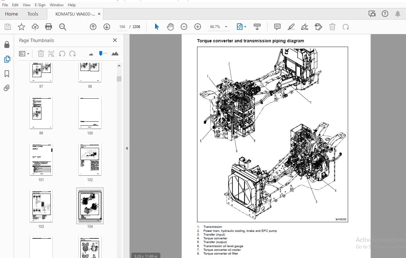
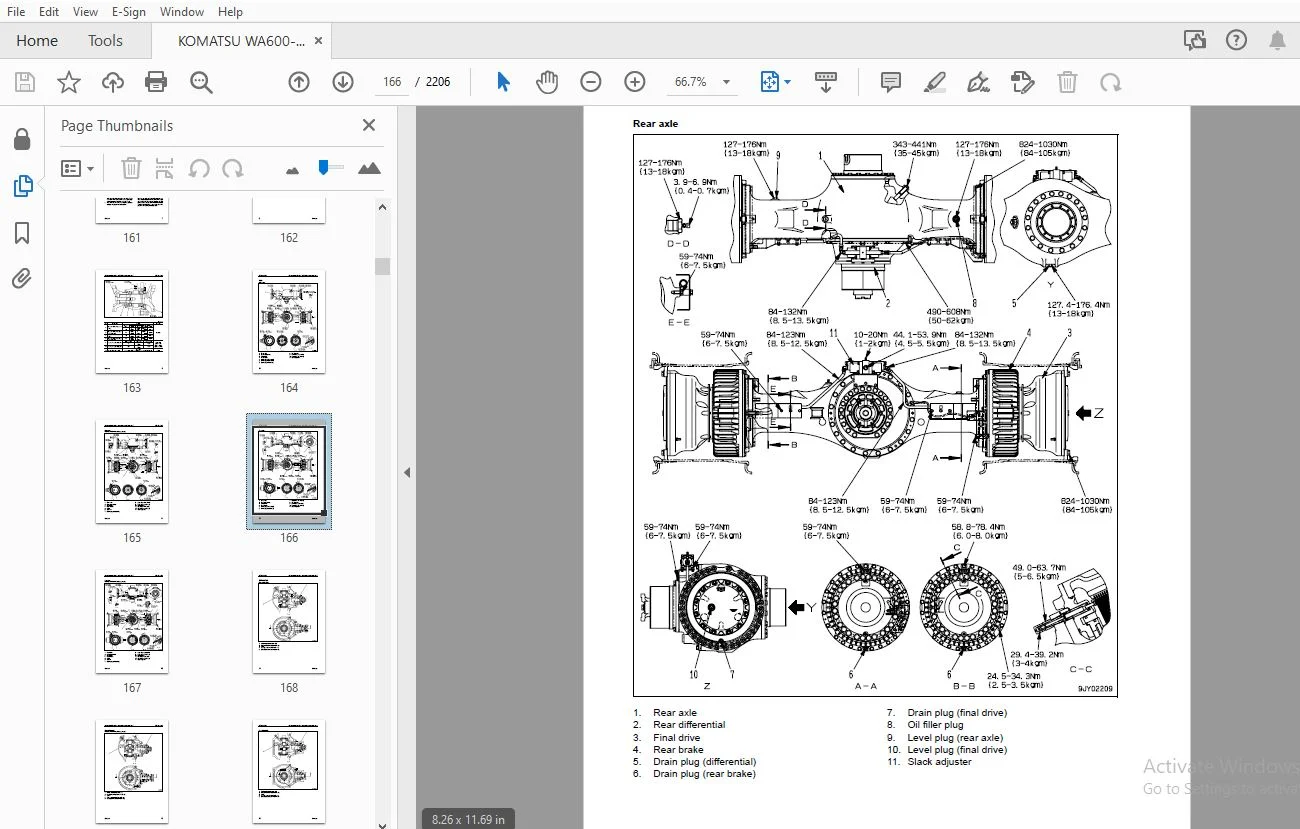
IMAGES PREVIEW OF THE MANUAL:
TABLE OF CONTENTS:
KOMATSU WA600-6 WHEEL LOADER SHOP MANUAL SEN00235-27 – PDF DOWNLOAD
Cover.....................................................................................................................................................................................   1
	00 Index and foreword.................................................................................................................................................................   3
		Index.............................................................................................................................................................................   3
			Composition of shop manual....................................................................................................................................................   4
			Table of contents.............................................................................................................................................................   6
		Foreword and general information .................................................................................................................................................  21
			Safety notice
................................................................................................................................................................  22
			How to read the shop manual
..................................................................................................................................................  27
			Explanation of terms for maintenance standard
................................................................................................................................  29
			Handling of electric equipment and hydraulic component
.......................................................................................................................  31
			Handling of connectors newly used for engines
................................................................................................................................  40
			How to read electric wire code
...............................................................................................................................................  43
			Precautions when carrying out operation
......................................................................................................................................  46
			Method of disassembling and connecting push-pull type coupler
................................................................................................................  49
			Standard tightening torque table
.............................................................................................................................................  52
			Conversion table..............................................................................................................................................................  56
	01 Specification......................................................................................................................................................................  63
		Specification and technical data..................................................................................................................................................  63
			Specification dimension drawing...............................................................................................................................................  64
			Specifications................................................................................................................................................................  65
			Weight table..................................................................................................................................................................  72
			Table of fuel, coolant and lubricants.........................................................................................................................................  74
	10 Structure, function and maintenance standard.......................................................................................................................................  77
		Engine and cooling system.........................................................................................................................................................  77
			Engine and cooling system.....................................................................................................................................................  78
				Engine mount and transmission mount.......................................................................................................................................  78
				Damper....................................................................................................................................................................  80
				Cooling system............................................................................................................................................................  82
				Cooling fan pump..........................................................................................................................................................  86
				Cooling fan motor.........................................................................................................................................................  94
		Power train, Part 1............................................................................................................................................................... 101
			Power train, Part 1........................................................................................................................................................... 102
				Power train............................................................................................................................................................... 102
				Power train system diagram................................................................................................................................................ 103
				Torque converter and transmission piping diagram.......................................................................................................................... 104
				Torque converter.......................................................................................................................................................... 106
				Modulation clutch......................................................................................................................................................... 115
				Torque converter regulator valve.......................................................................................................................................... 116
				Transmission.............................................................................................................................................................. 118
				Transfer.................................................................................................................................................................. 138
				Transmission control valve................................................................................................................................................ 140
				ECMV...................................................................................................................................................................... 143
				Main relief valve and torque converter relief valve....................................................................................................................... 150
				Lubrication relief valve.................................................................................................................................................. 152
		Power train, Part 2............................................................................................................................................................... 155
			Power train, Part 2........................................................................................................................................................... 156
				Torque converter oil cooler............................................................................................................................................... 156
				Torque converter oil filter............................................................................................................................................... 157
				Drive shaft............................................................................................................................................................... 159
				Center support............................................................................................................................................................ 162
				Axle...................................................................................................................................................................... 164
				Differential.............................................................................................................................................................. 168
				Limited slip differential................................................................................................................................................. 177
				Final drive............................................................................................................................................................... 182
		Steering system................................................................................................................................................................... 187
			Steering piping diagram....................................................................................................................................................... 190
			Steering column............................................................................................................................................................... 192
			Joystick steering lever linkage............................................................................................................................................... 193
			Joystick EPC valve............................................................................................................................................................ 194
			Lock valve.................................................................................................................................................................... 195
			Steering valve................................................................................................................................................................ 196
			Rotary valve.................................................................................................................................................................. 199
			Steering control valve........................................................................................................................................................ 202
			Two-way restrictor valve...................................................................................................................................................... 218
			Stop valve.................................................................................................................................................................... 219
			Steering pump................................................................................................................................................................. 220
			Steering cylinder............................................................................................................................................................. 234
			Emergency steering piping diagram............................................................................................................................................. 236
			Diverter valve................................................................................................................................................................ 237
			Emergency steering pump....................................................................................................................................................... 245
		Brake system...................................................................................................................................................................... 247
			Brake system.................................................................................................................................................................. 248
				Brake piping diagram...................................................................................................................................................... 248
				Brake..................................................................................................................................................................... 250
				Brake valve............................................................................................................................................................... 254
				Accumulator charge valve.................................................................................................................................................. 262
				EPC relief valve.......................................................................................................................................................... 268
				Accumulator (for brake)................................................................................................................................................... 270
				Slack adjuster............................................................................................................................................................ 272
				Parking brake............................................................................................................................................................. 276
				Parking brake solenoid valve.............................................................................................................................................. 278
				Emergency parking brake release valve..................................................................................................................................... 280
				Brake cooling pump........................................................................................................................................................ 281
		Undercarriage and frame........................................................................................................................................................... 283
			Undercarriage and frame....................................................................................................................................................... 284
				Axle mount................................................................................................................................................................ 284
				Center hinge pin.......................................................................................................................................................... 289
		Hydraulic system, Part 1.......................................................................................................................................................... 293
			Hydraulic system, Part 1...................................................................................................................................................... 294
				Hydraulic piping diagram.................................................................................................................................................. 294
				Work equipment control lever linkage...................................................................................................................................... 296
				Hydraulic tank............................................................................................................................................................ 298
				Work equipment hydraulic pump............................................................................................................................................. 300
		Hydraulic system, Part 2.......................................................................................................................................................... 321
			Hydraulic system, Part 2...................................................................................................................................................... 322
				Control valve............................................................................................................................................................. 322
				CLSS...................................................................................................................................................................... 336
				Each function and operation of each valve................................................................................................................................. 341
				Accumulator (for PPC circuit)............................................................................................................................................. 360
				Accumulator (for ECSS).................................................................................................................................................... 361
				Triple pump............................................................................................................................................................... 362
		Work equipment.................................................................................................................................................................... 365
			Work equipment................................................................................................................................................................ 366
				Work equipment linkage.................................................................................................................................................... 366
				Bucket.................................................................................................................................................................... 370
				Bucket positioner and boom kick-out....................................................................................................................................... 375
				Work equipment lubrication................................................................................................................................................ 376
				Work equipment cylinder................................................................................................................................................... 378
		Cab and its attachments........................................................................................................................................................... 381
			Cab and its attachments....................................................................................................................................................... 382
				ROPS cab.................................................................................................................................................................. 382
				Air conditioner........................................................................................................................................................... 384
		Electrical system, Part 1......................................................................................................................................................... 389
			Machine monitor system........................................................................................................................................................ 390
			Machine monitor............................................................................................................................................................... 396
		Electrical system, Part 2......................................................................................................................................................... 453
			Electrical system, Part 2..................................................................................................................................................... 454
				Work equipment control system............................................................................................................................................. 454
				Transmission controller system............................................................................................................................................ 490
		Electrical system, Part 3......................................................................................................................................................... 523
			Electric transmission control................................................................................................................................................. 524
			Engine starting/stopping circuit.............................................................................................................................................. 526
			Parking brake circuit......................................................................................................................................................... 529
			Sensor........................................................................................................................................................................ 533
			VHMS controller related....................................................................................................................................................... 556
			Work equipment electric lever................................................................................................................................................. 560
	20 Standard value table............................................................................................................................................................... 565
		Standard service value table...................................................................................................................................................... 565
			Standard service value table for engine....................................................................................................................................... 566
			Standard service value table for chassis...................................................................................................................................... 567
	30 Testing and adjusting.............................................................................................................................................................. 577
		Testing and adjusting, Part 1..................................................................................................................................................... 577
			Precautions before work....................................................................................................................................................... 579
			Tools for testing, adjusting, and troubleshooting............................................................................................................................. 580
			Sketches of special tools..................................................................................................................................................... 586
			Measuring engine speed........................................................................................................................................................ 587
			Measuring exhaust gas color................................................................................................................................................... 589
			Measuring exhaust temperature................................................................................................................................................. 590
			Adjusting valve clearance..................................................................................................................................................... 592
			Testing compression pressures................................................................................................................................................. 594
			Measuring blow-by pressure.................................................................................................................................................... 597
			Measuring engine oil pressure................................................................................................................................................. 598
			Testing EGR valve and bypass valve drive oil pressure......................................................................................................................... 599
			Measuring intake air (boost) pressure......................................................................................................................................... 601
			Handling fuel system equipment................................................................................................................................................ 602
			Releasing residual pressure in fuel system.................................................................................................................................... 602
			Testing fuel pressures........................................................................................................................................................ 603
			Testing return rate and leakage............................................................................................................................................... 604
			Bleeding air from fuel circuit................................................................................................................................................ 607
			Testing leakage in fuel system................................................................................................................................................ 609
			Handling reduced cylinder mode operation...................................................................................................................................... 610
			Handling no-injection cranking operation...................................................................................................................................... 610
			Handling controller voltage circuit........................................................................................................................................... 611
			Replacing and adjusting alternator and air conditioner compressor belt tension................................................................................................ 612
			Adjusting modulation clutch speed sensor and speed sensor..................................................................................................................... 613
			Measuring directional lever and gear shift lever (Steering wheel specification)............................................................................................... 615
			Testing and adjusting power train oil pressure................................................................................................................................ 616
			Flushing procedure for torque converter and transmission hydraulic circuit.................................................................................................... 630
			Method of moving machine when transmission valve is broken.................................................................................................................... 632
			Adjusting steering stop valve................................................................................................................................................. 634
		Testing and adjusting, Part 2..................................................................................................................................................... 637
			Measuring operating effort of AJSS lever (AJSS specification)................................................................................................................. 639
			Testing and adjusting AJSS lever angle sensor and frame angle sensor (AJSS specification)..................................................................................... 640
			Testing and adjusting steering stopper bolt (AJSS specification).............................................................................................................. 642
			Testing and adjusting steering wheel (Steering wheel specification)........................................................................................................... 644
			Testing steering oil pressure................................................................................................................................................. 646
			Bleeding air from steering cylinder circuit................................................................................................................................... 650
			Testing hydraulic drive fan................................................................................................................................................... 651
			Bleeding air from hydraulic drive fan circuit................................................................................................................................. 654
			Measuring brake pedal......................................................................................................................................................... 656
			Measuring brake performance................................................................................................................................................... 657
			Testing and adjusting accumulator charge pressure............................................................................................................................. 658
			Testing of accumulator nitrogen gas pressure and procedure for charging brake accumulator with nitrogen gas................................................................... 660
			Testing wheel brake oil pressure.............................................................................................................................................. 668
			Measuring wear of wheel brake disc............................................................................................................................................ 670
			Bleeding air from wheel brake circuit......................................................................................................................................... 671
			Releasing residual pressure in brake accumulator circuit...................................................................................................................... 672
			Testing parking brake performance............................................................................................................................................. 673
			Measuring parking brake oil pressure.......................................................................................................................................... 674
			Testing wear of parking brake disc............................................................................................................................................ 677
			Method of releasing parking brake manually.................................................................................................................................... 678
			Measuring and adjusting work equipment control lever.......................................................................................................................... 679
			Measuring work equipment oil pressure......................................................................................................................................... 680
			Bleeding air from work equipment circuit...................................................................................................................................... 685
			Releasing residual pressure in work equipment circuit......................................................................................................................... 686
			Testing of accumulator nitrogen gas pressure and procedure for charging ECSS accumulator with nitrogen gas.................................................................... 688
			Moving machine for removing operator cab...................................................................................................................................... 696
			Testing and adjusting bucket positioner....................................................................................................................................... 698
			Testing and adjusting lift arm position detecting lever....................................................................................................................... 700
			Checking proximity switch operation indication lamp........................................................................................................................... 701
			Preparations for work on troubleshooting of electric system................................................................................................................... 702
			Procedure for testing diodes.................................................................................................................................................. 706
		Testing and adjusting, Part 3..................................................................................................................................................... 709
			Machine monitor-based adjustment at replacement, disassembly and assembly, and additional installation for each sensor and controller......................................... 710
			Special functions of machine monitor (EMMS)................................................................................................................................... 713
		Testing and adjusting, Part 4..................................................................................................................................................... 789
			VHMS controller initial setting procedure (ORBCOMM installation specification)................................................................................................ 790
			VHMS controller initial setting procedure (IRIDIUM installation specification)................................................................................................ 812
			Precautions for replacing VHMS controller..................................................................................................................................... 834
			Pm-clinic inspection table.................................................................................................................................................... 840
	40 Troubleshooting.................................................................................................................................................................... 843
		Failure code table and fuse locations............................................................................................................................................. 843
			Failure codes list............................................................................................................................................................ 844
			Fuse locations................................................................................................................................................................ 857
		General information on troubleshooting............................................................................................................................................ 861
			Precautions before work....................................................................................................................................................... 862
			Points to remember when performing troubleshooting............................................................................................................................ 863
			How to proceed in troubleshooting............................................................................................................................................. 865
			Testing before troubleshooting................................................................................................................................................ 867
			Classification and procedures of troubleshooting.............................................................................................................................. 869
			Information in troubleshooting table.......................................................................................................................................... 873
			Troubleshooting method for disconnecting wiring harness of pressure sensor system............................................................................................. 875
			Phenomena looking like troubles and troubleshooting Nos....................................................................................................................... 878
			Connection table for connector pin numbers.................................................................................................................................... 880
			T- branch box and T- branch adapter table..................................................................................................................................... 915
		Troubleshooting by failure code (Display of code), Part 1......................................................................................................................... 919
			Failure code [1500L0] (TORQFLOW transmission: Double meshing)................................................................................................................. 921
			Failure code [15B0NX] (Transmission filter: Clogged).......................................................................................................................... 922
			Failure code [15SAL1] (ECMV F clutch: When command current is OFF, fill signal is ON)......................................................................................... 924
			Failure code [15SALH] (ECMV F clutch: When command current is ON, fill signal is OFF)......................................................................................... 926
			Failure code [15SBL1] (ECMV R clutch: When command current is OFF, fill signal is ON)......................................................................................... 928
			Failure code [15SBLH] (ECMV R clutch: When command current is ON, fill signal is OFF)......................................................................................... 930
			Failure code [15SEL1] (ECMV (1): When command current is OFF, fill signal is ON).............................................................................................. 932
			Failure code [15SELH] (ECMV (1): When command current is ON, fill signal is OFF).............................................................................................. 934
			Failure code [15SFL1] (ECMV (2): When command current is OFF, fill signal is ON).............................................................................................. 936
			Failure code [15SFLH] (ECMV (2): When command current is ON, fill signal is OFF).............................................................................................. 938
			Failure code [15SGL1] (ECMV (3): When command current is OFF, fill signal is ON).............................................................................................. 940
			Failure code [15SGLH] (ECMV (3): When command current is ON, fill signal is OFF).............................................................................................. 942
			Failure code [15SHL1] (ECMV (4): When command current is OFF, fill signal is ON).............................................................................................. 944
			Failure code [15SHLH] (ECMV (4): When command current is ON, fill signal is OFF).............................................................................................. 946
			Failure code [15W0NT] (Transmission modulation clutch: Overheating)........................................................................................................... 948
			Failure code [2F00MA] (Parking brake: Malfunction)............................................................................................................................ 949
			Failure code [2G42ZG] (Front accumulator: Low oil pressure)................................................................................................................... 952
		Troubleshooting by failure code (Display of code), Part 2......................................................................................................................... 955
			Failure code [2G43ZG] (Rear accumulator: Low oil pressure).................................................................................................................... 958
			Failure code [44K0L4] (Bucket positioner: ON/OFF signals disagree)............................................................................................................ 960
			Failure code [A000N1] (or VHMS_LED display: “n2” → “01”) (Engine: Overrun).................................................................................................... 963
			Failure code [AA1ANX] (Air cleaner: Clogging)................................................................................................................................. 964
			Failure code [AB00L6] (Alternator: Signal disagrees with operating state of engine)........................................................................................... 966
			Failure code [AB00MA] (Alternator: Malfunction)............................................................................................................................... 968
			Failure code [B@BAZG] (Engine oil pressure: Low error)........................................................................................................................ 970
			Failure code [B@BAZK] (Engine oil: Low level)................................................................................................................................. 971
			Failure code [B@BCNS] (Engine coolant temperature: Overheating)............................................................................................................... 972
			Failure code [B@BCZK] (Coolant: Low level).................................................................................................................................... 974
			Failure code [B@C7NS] (Brake oil: Overheating)................................................................................................................................ 976
			Failure code [b@CENS] (Torque converter oil: Overheating)..................................................................................................................... 977
			Failure code [B@CENS] (Torque converter oil: Overheating)..................................................................................................................... 978
			Failure code [B@GAZK] (Battery electrolyte: Low level)........................................................................................................................ 979
			Failure code [B@HANS] (Hydraulic oil: Overheating)............................................................................................................................ 981
			Failure code [CA111] (Abnormality in engine controller)....................................................................................................................... 982
			Failure code [CA115] (Engine Ne or Bkup speed sensor error)................................................................................................................... 985
			Failure code [CA122] (Charge (boost) pressure sensor high error).............................................................................................................. 986
			Failure code [CA123] (Charge (boost) pressure sensor low error)............................................................................................................... 988
			Failure code [CA131] (Throttle sensor high error)............................................................................................................................. 990
			Failure code [CA132] (Throttle sensor low error).............................................................................................................................. 993
			Failure code [CA135] (Engine oil pressure sensor high error).................................................................................................................. 996
			Failure code [CA141] (Engine oil pressure sensor low error)................................................................................................................... 998
			Failure code [CA144] (Coolant temperature sensor high error)..................................................................................................................1000
			Failure code [CA145] (Coolant temperature sensor low error)...................................................................................................................1002
			Failure code [CA153] (Charge (boost) temperature sensor high error)...........................................................................................................1004
			Failure code [CA154] (Charge (boost) temperature sensor low error)............................................................................................................1006
			Failure code [CA187] (Sensor power supply 2 low error)........................................................................................................................1008
			Failure code [CA212] (Engine oil temperature sensor high error)...............................................................................................................1010
			Failure code [CA213] (Engine oil temperature sensor low error)................................................................................................................1012
			Failure code [CA221] (Atmospheric pressure sensor high error).................................................................................................................1014
			Failure code [CA222] (Atmospheric pressure sensor low error)..................................................................................................................1016
			Failure code [CA227] (Sensor power supply 2 high error).......................................................................................................................1018
		Troubleshooting by failure code (Display of code), Part 3.........................................................................................................................1021
			Failure code [CA234] (Engine overspeed).......................................................................................................................................1023
			Failure code [CA238] (Ne speed sensor power supply error).....................................................................................................................1024
			Failure code [CA263] (Fuel temperature sensor high error).....................................................................................................................1026
			Failure code [CA265] (Fuel temperature sensor low error)......................................................................................................................1028
			Failure code [CA271] (PCV1 Short circuit).....................................................................................................................................1030
			Failure code [CA272] (PCV1 Disconnection).....................................................................................................................................1031
			Failure code [CA273] (PCV2 Short circuit).....................................................................................................................................1032
			Failure code [CA274] (PCV2 Disconnection).....................................................................................................................................1033
			Failure code [CA322] (Injector #1 open/short error)...........................................................................................................................1034
			Failure code [CA323] (Injector #5 open/short error)...........................................................................................................................1036
			Failure code [CA324] (Injector #3 open/short error)...........................................................................................................................1038
			Failure code [CA325] (Injector #6 open/short error)...........................................................................................................................1040
			Failure code [CA331] (Injector #2 open/short error)...........................................................................................................................1042
			Failure code [CA332] (Injector #4 open/short error)...........................................................................................................................1044
			Failure code [CA342] (Calibration code inconsistency).........................................................................................................................1046
			Failure code [CA351] (Injectors drive circuit error)..........................................................................................................................1047
			Failure code [CA352] (Sensor power supply 1 low error)........................................................................................................................1048
			Failure code [CA386] (Sensor power supply 1 high error).......................................................................................................................1050
			Failure code [CA431] (Idle validation switch error)...........................................................................................................................1051
			Failure code [CA432] (Idle validation action error)...........................................................................................................................1054
			Failure code [CA441] (Battery voltage low error)..............................................................................................................................1057
			Failure code [CA442] (Battery voltage high error).............................................................................................................................1058
			Failure code [CA449] Common rail pressure high error 2........................................................................................................................1059
			Failure code [CA451] (Common rail pressure sensor high error).................................................................................................................1060
			Failure code [CA452] (Common rail pressure sensor low error)..................................................................................................................1062
			Failure code [CA553] (Common rail pressure high error 1)......................................................................................................................1064
			Failure code [CA554] Common rail pressure sensor in range error...............................................................................................................1065
			Failure code [CA559] (Supply pump pressure very low error 1)..................................................................................................................1066
			Failure code [CA689] (Engine Ne speed sensor error)...........................................................................................................................1070
			Failure code [CA731] (Engine Bkup speed sensor phase error)...................................................................................................................1072
			Failure code [CA757] (All continuous data lost error).........................................................................................................................1073
			Failure code [CA778] (Engine Bkup speed sensor error).........................................................................................................................1074
			Failure code [CA1228] (EGR valve servo error 1)...............................................................................................................................1076
			Failure code [CA1625] (EGR valve servo error 2)...............................................................................................................................1077
			Failure code [CA1626] (Bypass valve solenoid current high error)..............................................................................................................1078
			Failure code [CA1627] (Bypass valve solenoid current low error)...............................................................................................................1080
			Failure code [CA1628] (Bypass valve servo error 1)............................................................................................................................1082
			Failure code [CA1629] (Bypass valve servo error 2)............................................................................................................................1083
			Failure code [CA1631] (Bypass valve lift sensor high error)...................................................................................................................1084
			Failure code [CA1632] (Bypass valve lift sensor low error)....................................................................................................................1086
			Failure code [CA1633] (KOMNET datalink timeout error).........................................................................................................................1088
		Troubleshooting by failure code (Display of code), Part 4.........................................................................................................................1091
			Failure code [CA2185] Throttle sensor supply voltage high error...............................................................................................................1094
			Failure code [CA2186] Throttle sensor power supply low error..................................................................................................................1096
			Failure code [CA2249] Supply pump pressure very low error 2...................................................................................................................1098
			Failure code [CA2271] EGR valve lift sensor high error........................................................................................................................1100
			Failure code [CA2272] EGR valve lift sensor low error.........................................................................................................................1102
			Failure code [CA2351] EGR valve solenoid operation short circuit..............................................................................................................1104
			Failure code [CA2352] EGR valve solenoid operation disconnect.................................................................................................................1106
			Failure code [CA2555] Intake air heater relay open circuit error..............................................................................................................1108
			Failure code [CA2556] Intake air heater relay short circuit error.............................................................................................................1110
			Failure code [D191KA] AJSS neutral safety relay open circuit..................................................................................................................1112
			Failure code [D191KB] AJSS neutral safety relay short circuit.................................................................................................................1114
			Failure code [D192KA] ECSS solenoid: Disconnection............................................................................................................................1116
			Failure code [D192KB] ECSS solenoid: Short circuit............................................................................................................................1117
			Failure code [D192KY] ECSS solenoid: Short circuit with power supply line.....................................................................................................1118
			Failure code [D198KA] Transmission oil pressure bypass solenoid: Disconnection................................................................................................1119
			Failure code [D198KB] Transmission oil pressure bypass solenoid: Short circuit................................................................................................1120
			Failure code [D198KY] Transmission oil pressure bypass solenoid: Short circuit with power supply line.........................................................................1121
			Failure code [D5ZHKA] Terminal C signal open circuit..........................................................................................................................1122
			Failure code [D5ZHKB] Terminal C signal short circuit.........................................................................................................................1124
			Failure code [D5ZHKZ] Terminal C signal open or short circuit.................................................................................................................1126
			Failure code [D5ZHL6] Terminal C signal disagrees with run and stop of engine.................................................................................................1128
			Failure code [DA80L4] Auto-greasing controller disagrees with ON/OFF signal...................................................................................................1130
			Failure code [DAF3KK] Machine monitor: Source voltage low (input).............................................................................................................1132
			Failure code [DAF5KP] Machine monitor: Output voltage low.....................................................................................................................1134
			Failure code [DAFRKR] CAN communication with machine monitor: Communication error (Abnormality in target component system)....................................................1136
			Failure code [DAQ0KK] Transmission controller: Source voltage low.............................................................................................................1137
			Failure code [DAQ0KT] Transmission controller: Defect in controller...........................................................................................................1140
			Failure code [DAQ2KK] Transmission controller load power supply line: Source voltage low (Input)..............................................................................1141
			Failure code [DAQ9KQ] Transmission controller model selection: Model selection signal disagreement............................................................................1144
			Failure code [DAQRKR] CAN communication with transmission controller: Communication error (Abnormality in target component system)............................................1145
			Failure code [DAQRMA] Transmission controller (Option setting): Malfunction...................................................................................................1150
		Troubleshooting by failure code (Display of code), Part 5.........................................................................................................................1153
			Failure code [DB2RKR] CAN communication from engine controller: Communication error (Abnormality in target component system)..................................................1156
			Failure code [DB90KK] Work equipment controller: Source voltage low (input)...................................................................................................1159
			Failure code [DB90KT] Work equipment controller: Defect in controller.........................................................................................................1162
			Failure code [DB92KK] Work equipment controller load power supply line: Source voltage low (input)............................................................................1163
			Failure code [DB95KX] Work equipment controller power supply output: Out of range.............................................................................................1166
			Failure code [DB99KQ] Work equipment controller model selection: Model selection signal disagreement..........................................................................1168
			Failure code [DB9RKR] CAN communication with work equipment controller: Communication error (Abnormality in target component system)..........................................1169
			Failure code [DB9RMA] Work equipment controller (Option setting): Malfunction.................................................................................................1170
			Failure code [DB9RMC] CAN communication with transmission controller: Malfunction.............................................................................................1171
			Failure code [DBB0KK] or change of VHMS_LED display from "n9" to "01" (VHMS controller: Source voltage low (input))...........................................................1172
			Failure code [DBB0KQ] or change of VHMS_LED display from "nF" to "11" (VHMS controller: Disagreement of model selection signals)..............................................1174
			Failure code [DBB3KK] or change of VHMS_LED display from "n9" to "05" (VHMS controller battery power supply: Source voltage low (input))......................................1176
			Failure code [DBB5KP] or change of VHMS_LED display from "n9" to "04" (VHMS controller 5 V power supply output: Output voltage low)...........................................1178
			Failure code [DBB6KP] or change of VHMS_LED display from "n9" to "02" (VHMS controller 24V power supply output: Output voltage low)...........................................1180
			Failure code [DBB7KP] or change of VHMS_LED display from "n9" to "03" (VHMS controller 12V power supply output: Output voltage low)...........................................1182
			Failure code [DBBQKR] or change of VHMS_LED display from "n8" to "02" (CAN communication of VHMS controller: Communication error (Abnormality in target component system))....1184
			Failure code [DD15LD] t switch (Panel switch 1): Switch is kept pressed for long time.........................................................................................1186
			Failure code [DD16LD] U switch (Panel switch 2): Switch is kept pressed for long time.........................................................................................1188
			Failure code [DD17LD] < switch (Panel switch 3): Switch is kept pressed for long time.........................................................................................1190
			Failure code [DD18LD] > switch (Panel switch 4): Switch is kept pressed for long time.........................................................................................1192
			Failure code [DD1ALD] Remote positioner raise/lower set switch (raise): Switch is kept pressed for long time..................................................................1194
			Failure code [DD1BLD] Remote positioner raise/lower set switch (lower): Switch is kept pressed for long time..................................................................1196
			Failure code [DD1CLD] Load meter subtotal switch: Switch is kept pressed for long time........................................................................................1198
			Failure code [DD1FLD] Load meter mode selector switch (A/B): Switch is kept pressed for long time.............................................................................1200
			Failure code [DD1GLD] Load meter mode selector switch (+/–): Switch is kept pressed for long time.............................................................................1202
		Troubleshooting by failure code (Display of code), Part 6.........................................................................................................................1205
			Failure code [DD1HLD] Load meter display selector switch: Switch is kept pressed for long time................................................................................1208
			Failure code [DDA7L4] RPM set ON/OFF switch: ON-OFF signals disagree..........................................................................................................1210
			Failure code [DDA8KB] RPM set idle-up/down selector switch (idle-up): Short circuit...........................................................................................1212
			Failure code [DDA9KB] RPM set idle-up/down selector switch (idle-down): Short circuit.........................................................................................1215
			Failure code [DDD1LD] Remote positioner bucket angle set switch: Switch is kept pressed for long time.........................................................................1218
			Failure code [DDDBKA] Traction adjustment dial: Disconnection.................................................................................................................1222
			Failure code [DDDBKB] Traction adjustment dial: Short circuit.................................................................................................................1224
			Failure code [DDE5MA] Emergency steering drive switch: Malfunction............................................................................................................1226
			Failure code [DDK4KA] AJSS FNR switch: Disconnection..........................................................................................................................1228
			Failure code [DDK4KB] AJSS FNR switch: Short circuit..........................................................................................................................1230
			Failure code [DDK5L4] AJSS shift-up/down switch: ON/OFF signals disagree......................................................................................................1232
			Failure code [DDK6KA] FNR lever switch: Disconnection.........................................................................................................................1235
			Failure code [DDK6KB] FNR lever switch: Short circuit.........................................................................................................................1238
			Failure code [DDP5KA] Lock detection pressure switch of steering lock lever: Disconnection....................................................................................1240
			Failure code [DDT0L4] Shift mode selector switch: ON/OFF signals disagree.....................................................................................................1242
			Failure code [DDW9LD] Kick-down switch: Switch is kept pressed for long time..................................................................................................1244
			Failure code [DDWLLD] Hold switch: Switch is kept pressed for long time.......................................................................................................1246
			Failure code [DDY0LD] Load meter cancel switch: Switch is kept pressed for long time..........................................................................................1248
			Failure code [DF10KA] Transmission shift lever switch: Disconnection..........................................................................................................1250
			Failure code [DF10KB] Transmission shift lever switch: Short circuit..........................................................................................................1254
			Failure code [DGE5KX] (or VHMS_LED display: “n4” → “01”) Atmospheric temperature sensor: Out of input signal range............................................................1256
			Failure code [DGF1KA] Transmission oil temperature sensor: Disconnection......................................................................................................1258
			Failure code [DGF1KB] Transmission oil temperature sensor: Short circuit......................................................................................................1260
		Troubleshooting by failure code (Display of code), Part 7.........................................................................................................................1263
			Failure code [DGH2KX] Hydraulic oil temperature sensor: Out of input signal range.............................................................................................1266
			Failure code [DGR2KA] Rear brake oil temperature sensor: Disconnection........................................................................................................1268
			Failure code [DGR2KX] Rear brake oil temperature sensor: Out of input signal range............................................................................................1270
			Failure code [DGT1KA] (Torque converter oil temperature sensor: Disconnection)................................................................................................1272
			Failure code [DGT1KB] (Torque converter oil temperature sensor: Short circuit)................................................................................................1273
			Failure code [DGT1KX] Torque converter oil temperature sensor: Out of input signal range).....................................................................................1274
			Failure code [DGT4KA] (or VHMS_LED display: "n3" → "12") Exhaust gas temperature sensor (F): Disconnection....................................................................1276
			Failure code [DGT4KB] (or VHMS_LED display: "n3" → "11") Exhaust gas temperature sensor (F): Short circuit....................................................................1279
			Failure code [DGT5KA] (or VHMS_LED display: "n3" → "22") Exhaust gas temperature sensor (R): Disconnection....................................................................1282
			Failure code [DGT5KB] (or VHMS_LED display: "n3" → "21") Exhaust gas temperature sensor (R): Short circuit....................................................................1285
			Failure code [DH21KA] Work equipment pump oil pressure sensor: Disconnection..................................................................................................1288
			Failure code [DH21KB] Work equipment pump oil pressure sensor: Short circuit..................................................................................................1290
			Failure code [DHE5KB] (or VHMS_LED display: “n3” → “32”) Blow-by pressure sensor: Short circuit...............................................................................1292
			Failure code [DHE5KY] (or VHMS_LED display: “n3” → “31”) Blow-by pressure sensor: Short circuit with power supply line........................................................1294
			Failure code [DHPCKX] (Lift arm cylinder bottom pressure sensor: Out of input signal range)...................................................................................1296
			Failure code [DHPDKX] (Lift arm cylinder head pressure sensor: Out of input signal range).....................................................................................1299
			Failure code [DHT2L6] Transmission filter clogging sensor: Signal disagrees with operating state of engine....................................................................1302
			Failure code [DHT8KX] (or VHMS_LED display: “n5” → “33”) Steering oil pressure sensor: Out of input signal range..............................................................1304
			Failure code [DHTBKA] Modulation clutch oil pressure sensor: Disconnection....................................................................................................1308
			Failure code [DHTBKB] Modulation clutch oil pressure sensor: Short circuit....................................................................................................1310
			Failure code [DHU2KX] (or VHMS_LED display: “n7” → “11”) Front brake oil pressure sensor (F): Out of input signal range.......................................................1312
			Failure code [DHU3KX] (or VHMS_LED display: “n7” → “12”) Rear brake oil pressure sensor (R): Out of input signal range........................................................1314
			Failure code [DK30KA] AJSS lever angle sensor: Disconnection..................................................................................................................1316
			Failure code [DK30KY] AJSS lever angle sensor: Short circuit with power supply line...........................................................................................1318
		Troubleshooting by failure code (Display of code), Part 8.........................................................................................................................1321
			Failure code [DK59KA] Lift arm EPC lever potentiometer (Main): Disconnection..................................................................................................1323
			Failure code [DK59KY] Lift arm EPC lever potentiometer (Main): Short circuit with power supply line...........................................................................1326
			Failure code [DK59L8] Lift arm EPC lever potentiometer (Main): Analog signals disagree........................................................................................1328
			Failure code [DK5AKA] Lift arm EPC lever potentiometer (Sub): Disconnection...................................................................................................1332
			Failure code [DK5AKY] Lift arm EPC lever potentiometer (Sub): Short circuit with power supply line............................................................................1335
			Failure code [DK5BKA] Bucket EPC lever potentiometer (Main): Disconnection....................................................................................................1338
			Failure code [DK5BKY] Bucket EPC lever potentiometer (Main): Short circuit with power supply line.............................................................................1341
			Failure code [DK5BL8] Bucket EPC lever potentiometer (Main): Analog signals disagree..........................................................................................1343
			Failure code [DK5CKA] Bucket EPC lever potentiometer (Sub): Disconnection.....................................................................................................1347
			Failure code [DK5CKY] Bucket EPC lever potentiometer (Sub): Short circuit with power supply line..............................................................................1350
			Failure code [DK5DKA] 3-spool valve (attachment) EPC lever potentiometer (Main): Disconnection................................................................................1353
			Failure code [DK5DKY] 3-spool valve (attachment) EPC lever potentiometer (Main): Short circuit with power supply line.........................................................1356
			Failure code [DK5DL8] 3-spool valve (attachment) EPC lever potentiometer (Main): Analog signals disagree......................................................................1358
			Failure code [DK5EKA] 3-spool valve (attachment) EPC lever potentiometer (Sub): Disconnection.................................................................................1361
			Failure code [DK5EKY] 3-spool valve EPC lever potentiometer (Sub): Short circuit with power supply line.......................................................................1364
			Failure code [DKA0KA] Lift arm angle sensor: Disconnection....................................................................................................................1366
			Failure code [DKA0KX] Lift arm angle sensor: Out of input signal range........................................................................................................1369
			Failure code [DKA0KY] Lift arm angle sensor: Short circuit with power supply line.............................................................................................1370
			Failure code [DKA0L0] Lift arm angle sensor: Improper position................................................................................................................1372
		Troubleshooting by failure code (Display of code), Part 9.........................................................................................................................1375
			Failure code [DKD0KA] (Frame angle sensor: Disconnection).....................................................................................................................1378
			Failure code [DKD0KY] (Frame angle sensor: Short circuit with power supply line)..............................................................................................1380
			Failure code [DKD0KZ] (AJSS lever and frame angle sensor: Disconnection or short circuit).....................................................................................1382
			Failure code [DLFAKA] (Modulation clutch output shaft speed sensor: Disconnection)............................................................................................1386
			Failure code [DLFALC] (Modulation clutch output shaft speed sensor: Speed signals disagree)...................................................................................1388
			Failure code [DLT3KA] (Transmission output shaft speed sensor (2): Disconnection).............................................................................................1390
			Failure code [DLT3LC] (Transmission output shaft speed sensor (2): Speed signals disagree)....................................................................................1392
			Failure code [DLT4KB] (Transmission output shaft speed sensor (1): Short circuit).............................................................................................1394
			Failure code [DLT4KX] (Transmission output shaft speed sensor (1): Out of input signal range).................................................................................1396
			Failure code [DUM1KB] (Remote positioner raise indicator lamp: Short circuit).................................................................................................1398
			Failure code [DUM2KB] (Remote positioner lower indicator lamp: Short circuit).................................................................................................1400
			Failure code [DV00KB] (Alarm buzzer: Short circuit)...........................................................................................................................1402
			Failure code [DW4PKA] (Lift arm raise EPC solenoid: Disconnection)............................................................................................................1404
			Failure code [DW4PKB] (Lift arm raise EPC solenoid: Short circuit)............................................................................................................1406
			Failure code [DW4PKY] (Lift arm raise EPC solenoid: Short circuit with power supply line).....................................................................................1407
			Failure code [DW4QKA] (Lift arm lower EPC solenoid: Disconnection)............................................................................................................1408
			Failure code [DW4QKB] (Lift arm lower EPC solenoid: Short circuit)............................................................................................................1409
			Failure code [DW4QKY] (Lift arm lower EPC solenoid: Short circuit with power supply line).....................................................................................1410
			Failure code [DW4RKA] (Bucket tilt EPC solenoid: Disconnection)...............................................................................................................1411
			Failure code [DW4RKB] (Bucket tilt EPC solenoid: Short circuit)...............................................................................................................1412
			Failure code [DW4RKY] (Bucket tilt EPC solenoid: Short circuit with power supply line)........................................................................................1413
			Failure code [DW4SKA] (Bucket dump EPC solenoid: Disconnection)...............................................................................................................1414
			Failure code [DW4SKB] (Bucket dump EPC solenoid: Short circuit)...............................................................................................................1415
			Failure code [DW4SKY] (Bucket dump EPC solenoid: Short circuit with power supply line)........................................................................................1416
			Failure code [DW7BKA] (Fan reverse solenoid: Disconnection)...................................................................................................................1418
			Failure code [DW7BKB] (Fan reverse solenoid: Short circuit)...................................................................................................................1420
			Failure code [DW7BKY] (Fan reverse solenoid: Short circuit with power supply line)............................................................................................1422
			Failure code [DW7DKA] (Hydraulic drive fan neutral solenoid: Disconnection)...................................................................................................1423
			Failure code [DW7DKB] (Hydraulic drive fan neutral solenoid: Short circuit)...................................................................................................1424
			Failure code [DW7DKY] (Hydraulic drive fan neutral solenoid: Short circuit with power supply line)............................................................................1425
		Troubleshooting by failure code (Display of code), Part 10........................................................................................................................1427
			Failure code [DWM1KA] Work equipment neutral lock solenoid: Disconnection.....................................................................................................1430
			Failure code [DWM1KB] Work equipment neutral lock solenoid: Short circuit.....................................................................................................1432
			Failure code [DWM1KY] Work equipment neutral lock solenoid: Short circuit with power supply line..............................................................................1434
			Failure code [DWN6KA] Lift arm raise magnet detent solenoid: Disconnection....................................................................................................1436
			Failure code [DWN6KB] Lift arm raise magnet detent solenoid: Short circuit....................................................................................................1438
			Failure code [DWN6KY] Lift arm raise magnet detent solenoid: Short circuit with power supply line.............................................................................1440
			Failure code [DWN7KA] Lift arm float magnet detent solenoid: Disconnection....................................................................................................1442
			Failure code [DWN7KB] Lift arm float magnet detent solenoid: Short circuit....................................................................................................1444
			Failure code [DWN7KY] Lift arm float magnet detent solenoid: Short circuit with power supply line.............................................................................1446
			Failure code [DWN8KA] Bucket tilt magnet detent solenoid: Disconnection.......................................................................................................1448
			Failure code [DWN8KB] Bucket tilt magnet detent solenoid: Short circuit.......................................................................................................1450
			Failure code [DWN8KY] Bucket tilt magnet detent solenoid: Shorted with the power source.......................................................................................1452
			Failure code [DWNFKA] Modulation clutch cut-off release solenoid: Disconnection...............................................................................................1454
			Failure code [DWNFKB] Modulation clutch cut-off release solenoid: Short circuit...............................................................................................1456
			Failure code [DWNFKY] Modulation clutch cut-off release solenoid: Short circuit with power source line........................................................................1458
			Failure code [DX16KA] Fan pump EPC solenoid: Disconnection....................................................................................................................1460
			Failure code [DX16KB] Fan pump EPC solenoid: Short circuit....................................................................................................................1461
			Failure code [DX16KY] Fan pump EPC solenoid: Short circuit with power supply line.............................................................................................1462
			Failure code [DXA1KA] Pump PC-EPC solenoid: Disconnection.....................................................................................................................1463
			Failure code [DXA1KB] Pump PC-EPC solenoid: Short circuit.....................................................................................................................1464
			Failure code [DXF0KA] AJSS EPC solenoid: Disconnection........................................................................................................................1465
			Failure code [DXF0KB] AJSS EPC solenoid: Short circuit........................................................................................................................1466
			Failure code [DXH1KA] Lockup ECMV solenoid: Disconnection.....................................................................................................................1468
			Failure code [DXH1KB] Lockup ECMV solenoid: Short circuit.....................................................................................................................1470
			Failure code [DXH1KY] Lockup ECMV solenoid: Short circuit with power supply line..............................................................................................1472
			Failure code [DXH4KA] 1st clutch ECMV solenoid: Disconnection.................................................................................................................1474
			Failure code [DXH4KB] 1st clutch ECMV solenoid: Short circuit.................................................................................................................1476
			Failure code [DXH4KY] 1st clutch ECMV solenoid: Short circuit with power supply line..........................................................................................1478
		Troubleshooting by failure code (Display of code), Part 11........................................................................................................................1481
			Failure code [DXH5KA] 2nd clutch ECMV solenoid: Disconnection.................................................................................................................1484
			Failure code [DXH5KB] 2nd clutch ECMV solenoid: Short circuit.................................................................................................................1486
			Failure code [DXH5KY] 2nd clutch ECMV solenoid: Short circuit with power supply line..........................................................................................1488
			Failure code [DXH6KA] 3rd clutch ECMV solenoid: Disconnection.................................................................................................................1490
			Failure code [DXH6KB] 3rd clutch ECMV solenoid: Short circuit.................................................................................................................1492
			Failure code [DXH6KY] 3rd clutch ECMV solenoid: Short circuit with power supply line..........................................................................................1494
			Failure code [DXH7KA] R clutch ECMV solenoid: Disconnection...................................................................................................................1496
			Failure code [DXH7KB] R clutch ECMV solenoid: Short circuit...................................................................................................................1498
			Failure code [DXH7KY] R clutch ECMV solenoid: Short circuit with power supply line............................................................................................1500
			Failure code [DXH8KA] F clutch ECMV solenoid: Disconnection...................................................................................................................1502
			Failure code [DXH8KB] F clutch ECMV solenoid: Short circuit...................................................................................................................1504
			Failure code [DXH8KY] F clutch ECMV solenoid: Short circuit with power supply line............................................................................................1506
			Failure code [DXHHKA] 4th clutch ECMV solenoid: Disconnection.................................................................................................................1508
			Failure code [DXHHKB] 4th clutch ECMV solenoid: Short circuit.................................................................................................................1510
			Failure code [DXHHKY] 4th clutch ECMV solenoid: Short circuit with power supply line..........................................................................................1512
			Failure code [DXHJKA] 3-spool valve extract EPC solenoid: Disconnection.......................................................................................................1514
			Failure code [DXHJKB] 3-spool valve extract EPC solenoid: Short circuit.......................................................................................................1516
			Failure code [DXHJKY] 3-spool valve extract EPC solenoid: Short circuit with power supply line................................................................................1517
			Failure code [DXHKKA] 3-spool valve retract EPC solenoid: Disconnection.......................................................................................................1518
			Failure code [DXHKKB] 3-spool valve retract EPC solenoid: Short circuit.......................................................................................................1520
			Failure code [DXHKKY] 3-spool valve retract EPC solenoid: Short circuit with power supply line................................................................................1521
			Failure code [DXHPKA] Modulation clutch solenoid: Disconnection...............................................................................................................1522
			Failure code [DXHPKB] Modulation clutch solenoid: Short circuit...............................................................................................................1524
			Failure code [DXHPKY] Modulation clutch solenoid: Short circuit with power source line........................................................................................1526
			Failure code [DXHPMA] Modulation clutch solenoid: Malfunction.................................................................................................................1528
			Failure code [F@BBZL] (or VHMS_LED display: “n3” o “38”) Blow-by pressure: High error.........................................................................................1530
			Failure code [F@BYNR] (or VHMS_LED display: “n3” → “62”) Exhaust gas temperature (F): Abnormal heat...........................................................................1532
			Failure code [F@BYNS] (or VHMS_LED display: “n3” → “61”) Exhaust gas temperature (F): Overheat................................................................................1534
			Failure code [F@BZNR] (or VHMS_LED display: “n3” → “72”) Exhaust gas temperature (R): abnormal heat...........................................................................1536
			Failure code [F@BZNS] (or VHMS_LED display “n3” → “71”) Exhaust gas temperature (R): Overheat.................................................................................1538
		Troubleshooting of electrical system (E-mode).....................................................................................................................................1541
			Before carrying out troubleshooting of electrical system......................................................................................................................1543
			Information in troubleshooting table..........................................................................................................................................1546
			E-1 Engine does not start.....................................................................................................................................................1547
			E-2 Wiper does not operate....................................................................................................................................................1557
			E-3 Windshield washer does not operate........................................................................................................................................1565
			E-4 Headlamp, clearance lamp, tail lamp, and license lamp do not light up or go off...........................................................................................1571
			E-5 Working lamp does not light up or go off..................................................................................................................................1587
			E-6 Step lamp does not light up or go off.....................................................................................................................................1594
			E-7 Turn signal lamp and hazard lamp do not light up or go off................................................................................................................1597
			E-8 Brake lamp does not light or it keeps lighting up.........................................................................................................................1607
			E-9 Backup lamp does not light or it keeps lighting up........................................................................................................................1610
			E-10 Backup buzzer does not sound or it keeps sounding........................................................................................................................1614
			E-11 Horn does not sound or it keeps sounding.................................................................................................................................1618
			E-12 Alarm buzzer does not sound or it keeps sounding.........................................................................................................................1622
			E-13 Air conditioner does not operate or stop.................................................................................................................................1624
			E-14 Electric priming pump does not operate or does not stop automatically....................................................................................................1626
			E-15 When starting switch is turned to ON position, machine monitor displays nothing..........................................................................................1628
		Troubleshooting of hydraulic and mechanical system (H-mode).......................................................................................................................1633
			Method of using troubleshooting chart.........................................................................................................................................1636
			Table of failure modes and causes.............................................................................................................................................1638
			H-1 Machine does not start....................................................................................................................................................1642
			H-2 Torque converter lockup is not switched (engine stalls)...................................................................................................................1644
			H-3 Torque converter lockup is not turned on..................................................................................................................................1645
			H-4 Travel speed is slow, thrusting force is weak, uphill traveling power is weak, and gear is not shifted....................................................................1646
			H-5 Shocks are large at the times of starting and shifting gear...............................................................................................................1648
			H-6 Time lag is large at the times of starting and shifting gear..............................................................................................................1650
			H-7 Torque converter oil temperature is high..................................................................................................................................1652
			H-8 Steering does not turn [machine with steering wheel]......................................................................................................................1653
			H-9 Steering does not turn [machine with AJSS]................................................................................................................................1654
			H-10 Turning, response of steering is poor [machine with steering wheel]......................................................................................................1655
			H-11 Turning, response of AJSS is poor [machine with AJSS]....................................................................................................................1656
			H-12 Steering is heavy [machine with steering wheel]..........................................................................................................................1657
			H-13 When machine turns, it shakes or makes large shocks [machine with steering wheel]........................................................................................1658
			H-14 When machine turns, it shakes or makes large shocks [machine with AJSS]..................................................................................................1659
			H-15 Wheel brake does not work or does not work well..........................................................................................................................1660
			H-16 Wheel brake is not released or it drags..................................................................................................................................1661
			H-17 Parking brake does not work or does not work well........................................................................................................................1662
			H-18 Parking brake is not released or it drags (including emergency release system)...........................................................................................1663
			H-19 Lift arm does not rise...................................................................................................................................................1664
			H-20 Lift arm speed is low or rising force of lift arm is insuff..............................................................................................................1665
			H-21 When rising, lift arm comes to move slowly at specific height............................................................................................................1666
			H-22 Lift arm cylinder cannot hold down bucket (Bucket floats)................................................................................................................1666
			H-23 Hydraulic drifts of lift arm occur often.................................................................................................................................1666
			H-24 Lift arm wobbles during operation........................................................................................................................................1666
			H-25 Bucket does not tilt back................................................................................................................................................1667
			H-26 Bucket speed is low or tilting back force is insufficient................................................................................................................1668
			H-27 Bucket comes to operate slowly in the midst of tilting-back..............................................................................................................1669
			H-28 Bucket cylinder cannot hold down bucket..................................................................................................................................1669
			H-29 Hydraulic drifts of bucket occur often...................................................................................................................................1669
			H-30 Bucket wobbles during travel with cargo (Work equipment valve is set to “HOLD”)..........................................................................................1669
			H-31 During operation of machine, engine speed lowers remarkably or engine stalls.............................................................................................1670
			H-32 Large shocks are made when work equipment starts and stops...............................................................................................................1670
			H-33 When work equipment circuit is relieved singly, other work equipment moves...............................................................................................1670
			H-34 ECSS does not operate, and pitching bouncing occurs......................................................................................................................1671
			H-35 Fan speed is abnormal (Fan sound and vibration are abnormally large or engine overheats).................................................................................1672
		Troubleshooting of engine (S-mode)................................................................................................................................................1675
			Method of using troubleshooting chart.........................................................................................................................................1677
			S-1 Engine does not start easily..............................................................................................................................................1680
			S-2 Engine does not start.....................................................................................................................................................1682
			S-3 Engine does not pick up smoothly..........................................................................................................................................1686
			S-4 Engine stops during operation.............................................................................................................................................1687
			S-5 Engine does not rotate smoothly (Hunting occurs)..........................................................................................................................1688
			S-6 Engine lacks output (or lacks power)......................................................................................................................................1689
			S-7 Exhaust smoke is black (Incomplete combustion)............................................................................................................................1690
			S-8 Oil is consumed much (or exhaust gas color is blue).......................................................................................................................1692
			S-9 Engine oil becomes contaminated quickly...................................................................................................................................1693
			S-10 Fuel consumption is excessive............................................................................................................................................1694
			S-11 Coolant contains oil (blows back or reduces).............................................................................................................................1695
			S-12 Oil pressure drops.......................................................................................................................................................1696
			S-13 Oil level rises (Water, fuel in oil).....................................................................................................................................1698
			S-14 Coolant temperature rises too high (Overheating).........................................................................................................................1700
			S-15 Abnormal noise is made...................................................................................................................................................1701
			S-16 Vibration is excessive...................................................................................................................................................1702
			S-17 Air cannot be bled from fuel circuit.....................................................................................................................................1704
	50 Disassembly and assembly...........................................................................................................................................................1707
		General information on disassembly andassembly....................................................................................................................................1707
			Precautions before work.......................................................................................................................................................1708
			How to read this manual.......................................................................................................................................................1709
			Coating materials list........................................................................................................................................................1711
			Special tools list............................................................................................................................................................1714
			Sketches of special tools.....................................................................................................................................................1724
		Engine and cooling system, Part 1.................................................................................................................................................1733
			Removal and installation of engine assembly...................................................................................................................................1734
			Removal and installation of radiator assembly.................................................................................................................................1739
			Removal and installation of air aftercooler assembly..........................................................................................................................1747
			Removal and installation of cooling fan and fan motor assembly................................................................................................................1749
			Removal and installation of damper assembly...................................................................................................................................1751
			Disassembly and assembly of damper assembly...................................................................................................................................1755
			Removal and installation of fuel tank assembly................................................................................................................................1760
			Removal and installation of engine hood assembly..............................................................................................................................1764
			Removal and installation of bulkhead assembly.................................................................................................................................1767
		Engine and cooling system, Part 2.................................................................................................................................................1773
			Removal and installation of fuel supply pump assembly.........................................................................................................................1774
			Removal and installation of cylinder head assembly............................................................................................................................1782
			Removal and installation of fuel injector assembly............................................................................................................................1803
			Removal and installation of engine front seal.................................................................................................................................1809
			Removal and installation of engine rear seal..................................................................................................................................1813
		Power train, Part 1...............................................................................................................................................................1819
			Removal and installation of parking brake assembly............................................................................................................................1820
			Removal and installation of torque converter and transmissionassembly.........................................................................................................1822
		Power train, Part 2...............................................................................................................................................................1833
			Disassembly and assembly of torque converter assembly.........................................................................................................................1834
			Disassembly and assembly of transmission assembly.............................................................................................................................1868
			Disassembly and assembly of transfer assembly.................................................................................................................................1906
			Disassembly and assembly of parking brake assembly............................................................................................................................1927
		Power train, Part 3...............................................................................................................................................................1939
			Removal and installation of front axle assembly...............................................................................................................................1940
			Removal and installation of rear axle assembly................................................................................................................................1943
			Removal and installation of center support assembly...........................................................................................................................1946
			Disassembly and assembly of center support assembly...........................................................................................................................1948
			Disassembly and assembly of differential assembly.............................................................................................................................1952
		Power train, Part 4...............................................................................................................................................................1973
			Removal and installation of final drive carrier assembly......................................................................................................................1974
			Disassembly and assembly of final drive carrier assembly......................................................................................................................1977
			Removal and installation of front final drive brake assembly..................................................................................................................1979
			Disassembly and assembly of final drive assembly..............................................................................................................................1982
		Brake system......................................................................................................................................................................1987
			Disassembly and assembly of brake assembly....................................................................................................................................1988
			Removal and installation of brake valve assembly..............................................................................................................................1999
			Disassembly and assembly of accumulator and charge valveassembly..............................................................................................................2001
			Disassembly and assembly of slack adjustor assembly...........................................................................................................................2004
		Undercarriage and frame...........................................................................................................................................................2009
			Removal and installation of center hinge pin..................................................................................................................................2010
			Removal and installation of counterweight assembly............................................................................................................................2021
		Hydraulic system..................................................................................................................................................................2023
			Removal and installation of hydraulic tank assembly...........................................................................................................................2024
			Removal and installation of hydraulic pump assembly...........................................................................................................................2028
			Removal and installation of control valve assembly............................................................................................................................2035
			Disassembly and assembly of control valve assembly............................................................................................................................2039
			Removal and installation of steering valve assembly...........................................................................................................................2045
			Removal and installation of ECSS accumulator assembly.........................................................................................................................2048
			Disassembly and assembly of hydraulic cylinder assembly.......................................................................................................................2050
		Work equipment....................................................................................................................................................................2059
			Removal and installation of work equipment assembly...........................................................................................................................2060
		Cab and its attachments...........................................................................................................................................................2069
			Removal and installation of operator's cab assembly...........................................................................................................................2070
			Removal and installation of operator's cab glass (stuck glass)................................................................................................................2076
			Removal and installation of floor frame assembly..............................................................................................................................2085
			Disassembly and assembly of operator’s seat assembly..........................................................................................................................2090
			Removal and installation of air conditioner unit assembly.....................................................................................................................2119
			Removal and installation of AJSS lever switch assembly........................................................................................................................2123
		Electrical system.................................................................................................................................................................2131
			Removal and installation of engine controller assembly........................................................................................................................2132
			Removal and installation of transmission controller assembly..................................................................................................................2134
			Removal and installation of loader controller assembly........................................................................................................................2136
			Removal and installation of VHMS controller assembly..........................................................................................................................2138
			Removal and installation of monitor assembly..................................................................................................................................2140
	90 Diagrams and drawings..............................................................................................................................................................2145
		Hydraulic diagrams and drawings...................................................................................................................................................2145
			Power train hydraulic circuit diagram.........................................................................................................................................2146
			Brake hydraulic circuit diagram...............................................................................................................................................2147
			Work equipment hydraulic circuit diagram......................................................................................................................................2149
		Electrical diagrams and drawings..................................................................................................................................................2159
			Air conditioner electrical circuit diagram....................................................................................................................................2161
			Steering wheel specification..................................................................................................................................................2163
				Electrical circuit diagram (1/10).........................................................................................................................................2163
				Electrical circuit diagram (2/10).........................................................................................................................................2165
				Electrical circuit diagram (3/10).........................................................................................................................................2167
				Electrical circuit diagram (4/10).........................................................................................................................................2169
				Electrical circuit diagram (5/10).........................................................................................................................................2171
				Electrical circuit diagram (6/10).........................................................................................................................................2173
				Electrical circuit diagram (7/10).........................................................................................................................................2175
				Electrical circuit diagram (8/10).........................................................................................................................................2177
				Electrical circuit diagram (9/10).........................................................................................................................................2179
				Electrical circuit diagram (10/10)........................................................................................................................................2181
			AJSS (Advanced Joystick Steering System) specification........................................................................................................................2183
				Electrical circuit diagram (1/10).........................................................................................................................................2183
				Electrical circuit diagram (2/10).........................................................................................................................................2185
				Electrical circuit diagram (3/10).........................................................................................................................................2187
				Electrical circuit diagram (4/10).........................................................................................................................................2189
				Electrical circuit diagram (5/10).........................................................................................................................................2191
				Electrical circuit diagram (6/10).........................................................................................................................................2193
				Electrical circuit diagram (7/10).........................................................................................................................................2195
				Electrical circuit diagram (8/10).........................................................................................................................................2197
				Electrical circuit diagram (9/10).........................................................................................................................................2199
				Electrical circuit diagram (10/10)........................................................................................................................................2201
			Connector arrangement diagram.................................................................................................................................................2203
DESCRIPTION:
KOMATSU WA600-6 WHEEL LOADER SHOP MANUAL SEN00235-27 – PDF DOWNLOAD
General precautions
1) Before carrying out any greasing or repairs, read all the safety labels stuck to the machine. For the locations of the safety labels and detailed explanation of precautions, see the Operation and Maintenance Manual.
2) Decide a place in the repair workshop to keep tools and removed parts. Always keep the tools and parts in their correct places. Always keep the work area clean and make sure that there is no dirt, water, or oil on the floor. Smoke only in the areas provided for smoking. Never smoke while working.
3) When carrying out any operation, always wear safety shoes and helmet. Do not wear loose work clothes, or clothes with buttons missing.
A. Always wear safety glasses when hitting parts with a hammer.
B. Always wear safety glasses when grinding parts with a grinder, etc.
4) When carrying out any operation with 2 or more workers, always agree on the operating procedure before starting. Always inform your fellow workers before starting any step of the operation. Before starting work, hang UNDER REPAIR warning signs in the operator’s compartment.
5) Only the approved personnel can do the work in a closed environment or in a prohibited area.
6) Only qualified workers must carry out work and operation which require license or qualification.
7) Keep all tools in good condition, learn the correct way to use them, and use the proper ones of them. Before starting work, thoroughly check the tools, machine, forklift, service car, etc.
8) If welding repairs are needed, always have a trained and experienced welder carry out the work. When carrying out welding work, always wear welding gloves, apron, shielding goggles, cap and other clothes suited for welding work.
9) Before starting work, warm up your body thoroughly to start work under good condition.
10) Avoid continuing work for long hours and take rests at proper intervals to keep your body in good condition. Take rests in specified safe places.
11) When you work in high places, use a platform.
12) Before you start the work, use the personal fall-arrest equipment to prevent falling. There is a danger of personal accident that you fall by slipping.
13) Always do the work correctly. If you find the unsafe behavior of co-worker, give him/her a notice and stop it.
14) Because there is a danger that you are caught, be very careful when the work is done in dangerous areas such as: when you go in the range where the lifted load possibly falls, or when you stand directly in front of tire, or when you are near the sliding parts.
15) When you handle chemical materials (such as nitrogen gas), see the MSDS (safety data sheet) and local guidelines, and get the important information (such as a safe handling method). Also, put on applicable protective equipment (such as protective goggles, gloves, and masks).
16) If necessary, cut out all the power sources (electricity, oil pressure, compressed air, etc.) before you start the work. If the machine has a lock mechanism, set it to the LOCK position and install the warning tag in a position where it is easy to see. Do not release the lock until the work is completed.
S.S 29/12/24


