Komatsu WA470-6 WA480-6 Wheel Loader Shop Manual PDF
$37.95
Komatsu WA470-6 WA480-6 Wheel Loader Shop Manual CEBM007102 – PDF DOWNLOAD
SERIAL NUMBERS
WA470-6 A45001 to A45999
WA480-6 A47001 to A47999
Description
Komatsu WA470-6 WA480-6 Wheel Loader Shop Manual CEBM007102 – PDF DOWNLOAD
FILE DETAILS:
Komatsu WA470-6 WA480-6 Wheel Loader Shop Manual CEBM007102 – PDF DOWNLOAD
Language : English
Pages : 1864
Downloadable : Yes
File Type : PDF
IMAGES PREVIEW OF THE MANUAL:
DESCRIPTION:
Komatsu WA470-6 WA480-6 Wheel Loader Shop Manual CEBM007102 – PDF DOWNLOAD
SERIAL NUMBERS
WA470-6 A45001 to A45999
WA480-6 A47001 to A47999
GENERAL PRECAUTIONS :
Mistakes in operation are extremely dangerous. Read the OPERATION & MAINTENANCE MANUAL carefully BEFORE operating the machine.
PREPARATIONS FOR WORK:
PRECAUTIONS DURING WORK :
TABLE OF CONTENTS:
Komatsu WA470-6 WA480-6 Wheel Loader Shop Manual CEBM007102 – PDF DOWNLOAD
SERIAL NUMBERS
WA470-6 A45001 to A45999
WA480-6 A47001 to A47999
FOREWORD 2
CONTENTS 2
SAFETY 33
Safety Notice 33
IMPORTANT SAFETY NOTICE 33
General Precautions 33
Preparations For Work 33
Precautions During Work 33
GENERAL 35
HOW TO READ THE SHOP MANUAL 36
Volumes 36
Distribution And Updating 36
Filing Method 36
Revised Edition Mark 36
Revisions 36
Symbols 36
HOISTING INSTRUCTIONS 37
Hoisting 37
Wire Ropes 37
MAINTENANCE STANDARD TERMINOLOGY 38
HANDLING ELECTRIC EQUIPMENT AND HYDRAULIC COMPONENTS 40
PUSH PULL COUPLER 49
Type 1 49
Disconnection 49
Connection 49
Type 2 50
Disconnection 50
Connection 50
Type 3 51
Disconnection 51
Connection 51
HANDLING OF CONNECTORS NEWLY USED FOR ENGINES 52
COATING MATERIALS 56
STANDARD TIGHTENING TORQUE 59
Standard Tightening Torque Of Bolts And Nuts 59
Tightening Torque Of Hose Nuts 60
Tightening Torque Of Split Flange Bolts 60
Tightening Torque For Flared Nuts 60
Table Of Tightening Torques For O-ring Boss Piping Joints 61
Table Of Tightening Torques For O-ring Boss Plugs 61
Tightening Torque Table For Hoses (Taper Seal Type And Face Seal Type) 61
ELECTRIC WIRE CODE 62
Classification By Thickness 62
Classification By Color And Code 62
CONVERSION TABLES 63
Method Of Using The Conversion Table 63
01 GENERAL 69
SPECIFICATIONS 70
Dimension Drawing 70
Specification Tables 72
WEIGHT TABLE 76
TABLE OF FUEL, COOLANT AND LUBRICANTS 78
10 STRUCTURE, FUNCTION AND MAINTENANCE STANDARD 81
ENGINE AND COOLING SYSTEM 86
Engine and Transmission Mounting 86
Cooling System 88
Cooling Fan Pump 90
Operation 94
Servo Valve 95
Cooling Fan Motor 98
Hydraulic Motor 100
Suction Valve 101
Operation of Reversible Valve 102
Safety Valve 103
POWER TRAIN 104
System Diagram 105
Drive Shaft 107
Power Train Piping Diagram 108
Torque Converter 110
Transmission 118
Transmission control valve 138
Left valve assembly 138
Right valve assembly 139
ECMV 141
MAIN AND TORQUE CONVERTER RELIEF VALVES 152
AXLE 154
Front axle 154
WA470-6 154
WA480-6 155
Rear axle 156
WA470-6 156
WA480-6 157
DIFFERENTIAL 158
Front Differential 158
Rear Differential 160
LIMITED SLIP DIFFERENTIAL 163
FINAL DRIVE 170
STEERING SYSTEM 175
Steering System Layout Drawing 175
Steering Column 176
Steering Pump 178
Pump Unit 180
Steering Valve 189
Orbit-roll Valve 202
Stop Valve 210
Steering Relief Valve 211
Steering Cylinder 212
Emergency steering motor 214
Emergency Steering Pump 215
Joystick Steering Lever Linkage 216
Electrical Steering Lever 217
Joystick EPC Valve 218
BRAKE SYSTEM 219
Brake Component Layout Drawing 219
Charge Valve 220
Brake Valve 226
Accumulator (for brake) 231
Slack Adjuster 232
Brake 234
Front Brake 234
Rear Brake 236
Parking Brake Control 239
Parking Brake 240
Parking Brake Solenoid Valve 242
Emergency Parking Brake Release Valve 244
UNDERCARRIAGE and FRAME 245
Axle Mount and Center Hinge Pin 245
Tires 249
HYDRAULIC SYSTEM 250
Hydraulic Component Layout Drawing 250
Work Equipment Control Lever Linkage 253
Multi-Function Mono-lever Type 254
Hydraulic Tank 255
Breather 256
Power Train Pump 257
Work Equipment Pump 258
Sectional View 260
LS Valve 264
PC Valve 269
PC-EPC Valve 274
Work Equipment Control Valve 278
CLSS 288
Basic principle 289
Function and Operation of Each Valve 292
Pressure Compensation Valve (Installed to cylinder head side of lift arm valve) 292
Shuttle valve in the pressure compensation valve 294
Supply of LS Pressure 296
LS Bypass Plug 297
ECSS Control Valve 298
Accumulator Charge Valve 301
PPC Valve 305
Work Equipment PPC Valve 305
Service PPC Valve (If equipped) 310
Accumulator (for PPC circuit) 312
Accumulator (for power train circuit) 313
Accumulator (for ECSS) (If equipped) 314
Work Equipment PPC Cut-off Solenoid Valve (If equipped) 315
WORK EQUIPMENT 318
Work Equipment Linkage 318
Bucket Positioner And Boom Kick-out 323
Work Equipment Cylinder 331
Lift Cylinder 331
Bucket Cylinder 331
CAB AND ITS ATTACHMENTS 333
Cab 333
Air Conditioner 334
Air Conditioner Piping Diagram 334
Refrigerant Circuit Diagram 336
Air Conditioner Unit 338
Blower and Intake Unit 342
Compressor 344
Condenser 345
Receiver 346
Air conditioner panel 347
ELECTRICAL SYSTEM 352
Machine Monitor System 352
System Circuit Diagram 354
Machine Monitor 356
Transmission Controller System 388
Transmission Controller Gear Shifting Control Function 388
System Circuit Diagram 424
Transmission Controller 426
Work Equipment Controller System 428
System Circuit Diagram 430
Work Equipment Controller 432
Electric Transmission Control 434
Combination Switch 436
Kickdown Switch and Hold Switch 438
Load Meter Cancel Switch and Load Meter Subtotal Switch 438
Multi-function Knob 439
Joystick Steering Knob 440
KOMTRAX System 441
KOMTRAX Terminal 442
Engine Starting Circuit 443
Engine Stopping Circuit 445
Preheating Circuit 446
Engine Power Mode Selector Circuit 447
Engine Output Derating Function 448
Automatic Warm-up Function 448
Parking Brake Circuit 449
Sensor 451
Transmission Input Speed Sensor 451
Transmission Output Speed Sensor 451
Cooling Fan Speed Sensor 451
Torque Converter Oil Temperature Sensor 452
Hydraulic Oil Temperature Sensor 452
Transmission Oil Temperature Sensor 452
Brake Oil Temperature Sensor 452
Work Equipment Pump Oil Pressure Sensor 453
Steering Pump Oil Pressure Sensor 453
Lift Cylinder Head Oil Pressure Sensor (machines equipped with load meter) 453
Lift Cylinder Bottom Oil Pressure Sensor (machines equipped with load meter) 453
Transmission Cut-off Oil Pressure Sensor 454
Coolant Level Sensor 455
Fuel Level Sensor 456
Air Cleaner Clogging Sensor (machine equipped with KOMTRAX) 457
Accelerator Pedal Sensor 458
Boom Kick-out Proximity Switch 459
Bucket Positioner Proximity Switch 459
Lift Arm Potentiometer (machines equipped with load meter) 460
20 STANDARD VALUE TABLES 461
STANDARD SERVICE VALUE TABLE 462
Standard Service Value Table for Engine 462
Standard Value Table For Chassis 463
Machine Posture and Procedure for Performance Measurement 469
30 TESTING AND ADJUSTING 471
TOOLS 475
Tools For Testing, Adjusting, And Troubleshooting 475
ENGINE COMPONENTS 481
Engine Speed 481
Exhaust Gas Color 483
Exhaust Temperature 485
Valve Clearance 487
Compression Pressure 489
Blow-by Pressure 491
Engine Oil Pressure 492
EGR Valve Drive Pressure 493
Intake Air (Boost) Pressure 495
FUEL SYSTEM 497
Handling Fuel System Equipment 497
Releasing Residual Pressure In Fuel System 497
Fuel Pressure 498
Fuel Return and Leak Amount 500
Bleeding Air From Fuel Circuit 503
Fuel Circuit for Leakage 505
Reduced Cylinder Mode Operation 506
No Injection Cranking Operation 506
Handling of Controller Voltage Circuit 506
EXHAUST SYSTEM AND PIPING 507
Check Muffler and Muffler Stack for Looseness and Damage 507
Check Muffler Function 507
Check Installed Condition of Cylinder Head and Manifolds 507
Check Engine Piping for Damage and Looseness 507
BELTS 508
Air Conditioner Compressor Belt 508
Testing 508
Adjusting 508
Adjusting Alternator Belt 509
Testing 509
Adjusting 509
TRANSMISSION SPEED SENSOR 510
DIRECTIONAL LEVER 511
Adjusting Directional Lever Length 511
Adjusting Gear Shift Lever Length 511
FNR AND GEAR SHIFT LEVERS 512
Testing FNR Lever and Gear Shift Lever 512
POWER TRAIN OIL PRESSURE 513
Testing and Adjusting Power Train Oil Pressure 513
Measurement 516
Adjustment 527
FLUSHING TRANSMISSION SYSTEM 528
Torque Converter and Transmission Hydraulic Circuit 528
TRANSMISSION VALVE FAILS 529
Moving Machine When Transmission Valve Is Broken 529
AXLE DRIVE AND DRIVE SHAFTS 532
Check of Axle Final Drive for Oil Leakage 532
Check of Drive Shafts for Looseness, Play and Damage 532
STEERING SYSTEM 533
Steering Stop Valve 533
Testing 533
Adjusting 533
Steering Wheel 535
Steering Oil Pressure 537
Adjusting 539
Bleeding Air From Steering Circuit 540
HYDRAULIC FAN 541
Hydraulic Drive Fan 541
Testing 541
Hydraulic Fan Speed Sensor 543
Adjustment 543
Bleeding Air From Hydraulic Drive Fan Circuit 545
BRAKE SYSTEM 547
Brake Pedal 547
Testing 547
Brake Pedal Linkage 548
Testing 548
Adjusting 548
Brake Performance 549
Testing 549
Accumulator Charge Pressure 550
Testing 550
Adjusting 551
Wheel Brake Oil Pressure 552
Testing 552
Check Wear of Wheel Brake Disc 555
Bleed Air From Wheel Brake Circuit 556
Release Residual Pressure in Brake Accumulator Circuit 557
Parking Brake Performance 557
Test 557
Parking Brake Oil Pressure 558
Testing 558
Wear Of Parking Brake Disc 560
Testing 560
Manual Release for Parking Brake 562
WORK EQUIPMENT 563
Work Equipment Control Lever 563
Testing 563
Work Equipment PPC Oil Pressure 564
Measuring 564
Adjusting 567
Work Equipment Oil Pressure 568
Testing 568
Adjusting 572
Bleeding Air From Work Equipment Circuit 573
Releasing Residual Pressure in Work Equipment Circuit 574
ACCUMULATOR 576
Nitrogen Gas Accumulator Pressure of ECSS 576
Testing 577
Charging Accumulator 579
Brake Accumulator Nitrogen Gas Pressure 583
Testing 584
Charging Accumulator 586
BUCKET POSITIONER 589
Testing 589
Adjusting 589
BOOM KICK-OUT 591
Testing 591
Adjusting 591
PROXIMITY SWITCH OPERATION PILOT LAMP 592
ELECTRICAL SYSTEM 593
Diode Testing Procedure 593
Electrical System Troubleshooting 594
Preparation 594
KOMTRAX SYSTEM 599
How to Start KOMTRAX Terminal Operations 599
Station Opening Check in Machine Side 600
Application for the Start of Use 603
Indicator Lamps of KOMTRAX Terminal 604
MACHINE MONITOR SYSTEM 607
Adjusting replaced, reassembled or added sensor, controller, etc with machine monitor 607
Special functions of machine monitor (EMMS) 610
Normal functions and special functions of machine monitor 610
Functions and flow of the service mode 611
Operator mode 614
Service Meter/clock Display Function (1) 614
Load Meter Function (if equipped) (2) 614
Odometer Display Function (3) 614
Maintenance Monitoring Function (4) 614
Telephone Number Input Function (5) 615
Language Selection Function (6) 615
Monitor Brightness Adjustment Function (7) 615
Time Adjustment Function (8) 616
Travel Speed/Engine Speed Display Selecting Function (9) 616
Travel Speed/Engine Speed Display/Non-Display Selecting Function (10) 616
Action Code Display Function (11) 616
Failure Code Display Function (12) 617
Service mode 618
Procedure For Switching To Service Mode And Screen Display (1) 618
Electrical System Fault History Display Function (ELECTRIC FAULT) (2) 619
Mechanical System Fault History Display Function (MACHINE FAULT) (3) 621
Real-Time Monitoring Function (REAL-TIME MONITOR) (4) 622
Engine Cylinder Cutout Function (CYLINDER CUT- OUT) (5) 644
No Injection Cranking Function (6) 645
Adjustment Function (TUNING) (7) 646
Maintenance Monitoring Function (8) 663
Operating Information Display Function (9) 669
OPTIONAL SELECT Function (10) 671
Machine Serial Number Input Function (11) 675
Machine Model Select Function (MACHINE) (12) 675
Initialize Function (13) 676
PM-CLINIC INSPECTION TABLE 677
WA470-6 S/N A45001 to A45999 677
WA480-6 S/N A47001 to A47999 680
40 TROUBLESHOOTING 683
FAILURE CODE TABLE 697
Fuse Locations 709
Locations and Numbers of Fuse Boxes and Slow Blow Fuse 711
POINTS TO REMEMBER WHEN TROUBLESHOOTING 712
SEQUENCE OF EVENTS IN TROUBLESHOOTING 714
Testing Before Troubleshooting 715
CLASSIFICATION AND TROUBLESHOOTING PROCEDURES 716
MODE CHART 717
Information Contained in Troubleshooting Table 720
CONNECTION TABLE FOR CONNECTOR PIN NUMBERS 722
X-Type Connectors 722
SWP-Type Connectors 724
M-Type Connectors 726
S-Type Connectors 728
MIC-Type Connectors 730
AMP040-Type Connectors 732
AMP070-Type Connectors 734
AMP Connector 736
L-Type Connector 736
PA-Type Connector 737
Bendix (MS) Connector 737
KES1 (Automobile) Connectors 738
F-Type Connector 739
HD30 Series Connectors 741
DT Series Connectors 747
DTM Series Connectors 749
DTHD Series Connectors 749
DTP Series Connectors 750
DRC26 Series Connectors 751
DRC12, 16 Series Connectors 753
AMP Connectors for Pump Controller (CH700) 754
BOSCH Connectors for Engine 755
SUMITOMO Connectors for Engine 756
CANNON Connector for Engine 757
AMP Connectors for Engine 758
FRAMATOME Connectors for Engine 759
PACKARD Connectors for Engine 761
DT Series Connectors for Engine 762
T-BRANCH BOX and T-BRANCH ADAPTER TABLE 763
FAILURE CODES 768
1500L0 769
TORQFLOW Transmission: Double Meshing 769
15SAL1 770
ECMV F Clutch: When Command Current is OFF, Fill Signal is ON 770
15SALH 772
ECMV F Clutch: When Command Current is ON, Fill Signal is OFF 772
15SBL1 774
ECMV R Clutch: When Command Current is OFF, Fill Signal is ON 774
15SBLH 776
ECMV R Clutch: When Command Current is ON, Fill Signal is OFF 776
15SEL1 778
ECMV 1st Clutch: When Command Current is OFF, Fill Signal is ON 778
15SELH 780
ECMV 1st Clutch: When Command Current is ON, Fill Signal is OFF 780
15SFL1 782
ECMV 2nd Clutch: When Command Current is OFF, FIll Signal is ON 782
15SFLH 784
ECMV 2nd Clutch: When Command Current is ON, Fill Signal is OFF 784
15SGL1 786
ECMV 3rd Clutch: When Command Current is OFF, Fill Signal is ON 786
15GLH 788
ECMV 3rd Clutch: When Command Current is ON, Fill Signal is OFF 788
15SHL1 790
ECMV 4th Clutch: When Command Current is OFF, Fill Signal is ON 790
15SHLH 792
ECMV 4th Clutch: When Command Current is ON, Fill Signal is OFF 792
2F00MA 794
Parking Brake: Malfunction 794
2G43ZG 796
Accumulator: Low Oil Pressure 796
44K0L4 798
Bucket Positioner: ON/OFF Signals Disagree 798
AA1ANX 802
Air Cleaner: Clogging 802
AB00L6 804
Alternator: Signal Disagrees with Operating State of Engine 804
AB00MA 806
Alternator: Malfunction 806
B@BAZG 808
Engine: Rotation Derating by Low Engine Oil Pressure 808
B@BAZK 810
Engine Oil: Low Level 810
B@BCNS 812
Coolant: Overheating 812
B@BCZK 814
Engine Coolant: Low Level 814
B@C7NS 816
Brake Oil: Overheating 816
b@CENS 818
Torque Converter Oil: Overheating 818
B@CENS 820
Torque Converter Oil: Overheating 820
B@HANS 822
Hydraulic Oil: Overheating 822
CA111 824
Abnormality in Engine Controller 824
CA115 827
Engine Ne or Bkup Speed Sensor Error 827
CA122 828
Charge Pressure Sensor High Error 828
CA123 830
Charge Pressure Sensor Low Error 830
CA131 832
Throttle Sensor High Error 832
CA132 834
Throttle Sensor Low Error 834
CA135 836
Engine Oil Pressure Sensor High Error 836
CA141 838
Engine Oil Pressure Sensor Low Error 838
CA144 840
Coolant Sensor High Error 840
CA145 842
Coolant Temperature Sensor Low Error 842
CA153 844
Charge Temperature Sensor High Error 844
CA154 846
Charge Temperature Sensor Low Error 846
CA187 848
Sensor Power Supply 2 Low Error 848
CA221 850
Atmospheric Pressure Sensor High Error 850
CA222 852
Atmospheric Pressure Sensor Low Error 852
CA227 853
Sensor Power Supply 2 High Error 853
CA234 856
Engine Overspeed 856
CA238 858
NE Speed Sensor Power Supply Error 858
CA263 860
Fuel Temperature Sensor High Error 860
CA265 862
Fuel Temperature Sensor Low Error 862
CA271 864
PCV1 Short Circuit 864
CA272 866
PCV1 Disconnection 866
CA273 868
PCV2 Short Circuit 868
CA274 870
PCV2 Disconnection 870
CA322 872
Injector #1 Open/Short Error 872
CA323 874
Injector #5 Open/Short Error 874
CA324 876
Injector #3 Open/Short Error 876
CA325 878
Injector #6 Open/Short Error 878
CA331 880
Injector #2 Open/Short Error 880
CA332 882
Injector #4 Open/Short Error 882
CA342 884
Calibration Code Inconsistency 884
CA351 886
Injectors Drive Circuit Error 886
CA352 888
Sensor Power Supply 1 Low Error 888
CA386 890
Sensor Power Supply 1 High Error 890
CA431 892
Idle Validation Switch Error 892
CA432 894
Idle Validation Action Error 894
CA441 896
Battery Voltage Low Error 896
CA442 900
Battery Voltage High Error 900
CA449 902
Common Rail Pressure High Error 2 902
CA451 904
Common Rail Pressure Sensor High Error 904
CA452 906
Common Rail Pressure Sensor Low Error 906
CA553 907
Common Rail Pressure High Error 1 907
CA554 908
Common Rail Pressure Sensor In-Range Error 908
CA559 909
Supply Pump Pressure Very Low Error 909
CA689 916
Engine Ne Speed Sensor Error 916
CA731 918
Engine Bkup Speed Sensor Phase Error 918
CA757 919
All Continuous Data Lost Error 919
CA778 920
Engine Bkup Speed Sensor Error 920
CA1228 922
EGR Valve Servo Error 1 922
CA1625 923
EGR Valve Servo Error 2 923
CA1633 924
KOMNET Datalink Timeout Error 924
CA2185 926
Throttle Sensor Supply Voltage High Error 926
CA2186 928
Throttle Sensor Power Supply Low Error 928
CA2249 930
Supply Pump Pressure Very Low Error 2 930
CA2271 931
EGR Valve Lift Sensor High Error 931
CA2272 933
EGR Valve Lift Sensor Low Error 933
CA2351 934
EGR Valve Solenoid Operation Short Circuit 934
CA2352 936
EGR Valve Solenoid Operation Disconnect 936
CA2555 938
Intake Heater Relay Disconnection Error 938
CA2556 940
Intake Heater Relay Short Circuit Error 940
D150KA 942
Emergency Steering Relay: Disconnection 942
D150KB 944
Emergency Steering Relay: Short Circuit 944
D150KY 946
Emergency Steering Relay: Short Circuit With Power Supply Line 946
D160KA 948
Backup Lamp Relay Output: Disconnection 948
D160KB 950
Backup Lamp Relay Output: Short Circuit 950
D191KA 952
Joystick Steering Neutral Safety Relay: Disconnection 952
D191KB 954
Joystick Steering Neutral Safety Relay: Short Circuit 954
D191KY 956
Joystick Steering Neutral Safety Relay: Short Circuit With Power Supply Line 956
D192KA 958
ECSS Solenoid: Disconnection 958
D192KB 960
ECSS Solenoid: Short Circuit 960
D192KY 962
ECSS Solenoid: Short Circuit With Power Supply Line 962
D193KA 964
Joystick Steering Solenoid Cut-Off Relay: Disconnection 964
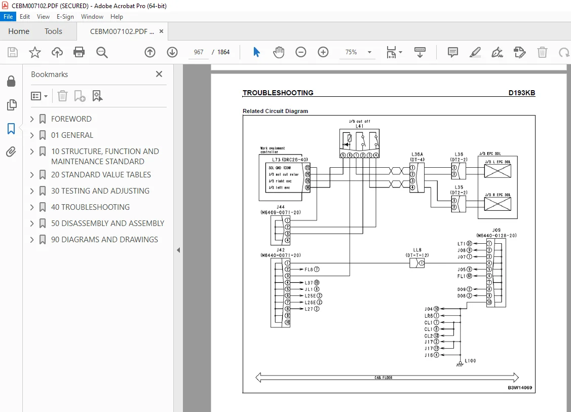
D193KB 966
Joystick steering solenoid cut-off relay: Short circuit 966
D193KY 968
Joystick Steering Solenoid Cut-Off Relay: Short Circuit With Power Supply Line 968
D5ZHKA 970
Terminal C Signal: Disconnection 970
D5ZHKB 974
Terminal C Signal: Short Circuit 974
D5ZHKZ 978
Terminal C Signal: Disconnection Or Short Circuit 978
D5ZHL6 982
Terminal C Signal: Signal Does Not Match Engine Running Or Stopped State 982
DA80L4 986
Auto Grease Controller: ON/OFF Signals Disagree 986
DAF3KK 988
Machine Monitor: Low Source Voltage (Input) 988
DAF5KP 990
Machine Monitor: Low Output Voltage 990
DAFRKR 994
CAN Communication With Machine Monitor: Defective Communication (Abnormality In Target Component System) 994
DAQ0KK 996
Transmission Controller: Low Source Voltage 996
DAQ0KT 998
Transmission Controller: Abnormality In Controller 998
DAQ1KA 999
Terminal ACC Input: Disconnection 999
DAQ2KK 1002
Transmission Controller Load Power Supply Line: Low Source Voltage (Input) 1002
DAQ9KQ 1004
Transmission Controller Model Selection: Disagreement of Model Selection Signals 1004
DAQRKR 1005
CAN Communication with Transmission Controller: Defective Communication (Abnormality in Target Component System) 1005
DAQRMA 1007
Transmission Controller Option Setting: Malfunction 1007
DB2RKR 1008
CAN Communication with Engine Controller: Defective Communication (Abnormality in Target Component System) 1008
DB90KK 1010
Work Equipment Controller: Low Source Voltage (Input) 1010
DB90KT 1012
Work Equipment Controller: Abnormality in Controller 1012
DB92KK 1014
Work Equipment Controller Load Power Supply Line: Low Source Voltage (Input) 1014
DB95KX 1016
Work Equipment Controller Power Supply Output: Out of Input Signal Range 1016
DB99KQ 1018
Work Equipment Controller Model Selection: Disagreement in Model Selection Signals 1018
DB9RKR 1019
CAN Communication With Work Equipment Controller: Defective Communication (Abnormality in Target Component System) 1019
DB9RMA 1021
Work equipment controller option setting: Malfunction 1021
DB9RMC 1022
CAN Communication With Transmission Controller, Engine Controller and Machine Monitor: Defective Operation 1022
DD15LD 1026
n Switch (Panel Switch 1): Switch Is Kept Pressed For Long Time 1026
DD16LD 1028
Ø Switch (Panel Switch 2): Switch is Kept Pressed for Long Time 1028
DD17LD 1030
< Switch (Panel Switch 3): Switch Is Kept Pressed For Long Time 1030
DD18LD 1032
> Switch (Panel Switch 4): Switch Is Kept Pressed For Long Time 1032
DD1ALD 1034
Remote Positioner Raise/lower Set Switch (Raise): Switch Is Kept Pressed For Long Time 1034
DD1BLD 1036
Remote Positioner Raise/lower Set Switch (Lower): Switch Is Kept Pressed For Long Time 1036
DD1CLD 1038
Load Meter Subtotal Switch: Switch Is Kept Pressed For Long Time 1038
DD1FLD 1040
Load Meter Mode Selector Switch (A/B): Switch Is Kept Pressed For Long Time 1040
DD1GLD 1042
Load Meter Mode Selector Switch (+/-): Switch Is Kept Pressed For Long Time 1042
DD1HLD 1044
Load Meter Display Selector Switch: Switch Is Kept Pressed For Long Time 1044
DD1NLD 1046
Fan Reverse Switch: Switch Is Kept Pressed For Long Time 1046
DD1NL4 1048
Fan Automatic Reverse Switch: Switch Is Kept Pressed For Long Time 1048
DDB6L4 1050
Parking Brake Switch (Neutralizer): ON/OFF Signals Disagree 1050
DDD1LD 1054
Remote Positioner Bucket Angle Set Switch: Switch Is Kept Pressed For Long Time 1054
DDE5MA 1056
Emergency Steering Drive Switch: Malfunction 1056
DDK3KA 1058
Right FNR Switch: Disconnection 1058
DDK4KA 1061
Joystick Steering FNR Switch: Disconnection 1061
DDK5L4 1064
Joystick Steering Shift-Up/Down Switch: ON/OFF Signals Disagree 1064
DDK6KA 1066
FNR Lever Switch: Disconnection 1066
DDK6KB 1070
FNR Lever Switch: Short Circuit 1070
DDS5KA 1072
Steering Pressure Switch Signal: Disconnected 1072
DDS5KB 1074
Steering pressure Switch Signal: Short Circuit 1074
DDS5L6 1076
Steering: Low Oil Pressure 1076
DDT0L4 1078
Shift Mode Selector Switch: ON/OFF Signals Disagree 1078
DDT4LD 1080
Transmission Cut-Off Set Switch: Switch Is Kept Pressed For Long Time 1080
DDW9LD 1082
Kick-Down Switch: Switch Is Kept Pressed For Long Time 1082
DDWLLD 1084
Hold Switch: Switch Is Kept Pressed For Long Time 1084
DDY0LD 1086
Load Meter Cancel Switch: Switch Is Kept Pressed For Long Time 1086
DF10KA 1088
Transmission Shift Lever Switch: Disconnected 1088
DF10KB 1092
Transmission Shift Lever Switch: Short Circuit 1092
DGF1KA 1094
Transmission Oil Temperature Sensor: Disconnected 1094
DGF1KB 1096
Transmission Oil Temperature Sensor: Short Circuit 1096
DGH2KX 1098
Hydraulic Oil Temperature Sensor: Out Of Input Signal Range 1098
DGR2KA 1100
Rear Brake Oil Temperature Sensor: Disconnected 1100
DGR2KX 1102
Rear Brake Oil Temperature Sensor: Out Of Input Signal Range 1102
DGT1KX 1104
Torque converter oil temperature sensor: Out of input signal range 1104
DH21KA 1106
Loader Pump Pressure Sensor: Disconnection 1106
DH21KB 1108
Loader Pump Pressure Sensor: Power Supply Line Short 1108
DHPCKX 1110
Lift Arm Cylinder Bottom Pressure Sensor: Out Of Input Signal Range 1110
DHPDKX 1112
Lift Arm Cylinder Head Pressure Sensor: Out Of Input Signal Range 1112
DHT1KX 1114
Transmission Cut-Off Pressure Sensor: Out Of Input Signal Range 1114
DHT8KA 1116
Steering Pump Pressure Sensor: Disconnection 1116
DHT8KB 1118
Steering Pump Pressure Sensor: Short Circuit 1118
DK59KA 1120
Lift Arm EPC Lever Potentiometer (Main): Disconnection 1120
DK59KY 1123
Lift Arm EPC Lever Potentiometer (Main): Short Circuit With Power Supply Line 1123
DK59L8 1126
Lift Arm EPC Lever Potentiometer (Main): Analog Signals Disagree 1126
DK5AKA 1129
Lift Arm EPC Lever Potentiometer (Sub): Disconnection 1129
DK5AKY 1132
Lift Arm EPC Lever Potentiometer (Sub): Short Circuit With Power Supply Line 1132
DK5BKA 1135
Bucket EPC Lever Potentiometer (Main): Disconnection 1135
DK5BKY 1138
Bucket EPC Lever Potentiometer (Main): Short Circuit With Power Supply Line 1138
DK5BL8 1141
Bucket EPC Lever Potentiometer (Main): Analog Signals Disagree 1141
DK5CKA 1144
Bucket EPC Lever Potentiometer (Sub): Disconnection 1144
DK5CKY 1147
Bucket EPC Lever Potentiometer (Sub): Short Circuit With Power Supply Line 1147
DK5FKA 1150
Joystick Steering EPC Lever Potentiometer (Main): Disconnection 1150
DK5FKY 1154
Joystick steering EPC lever potentiometer (Main): Short circuit with power supply line 1154
DK5GKA 1156
Joystick Steering EPC Lever Potentiometer (Sub): Disconnection 1156
DK5GKY 1159
Joystick Steering EPC Lever Potentiometer (Sub): Short Circuit With Power Supply Line 1159
DK5FL8 1161
Joystick Steering EPC Lever Potentiometer (Main): Analog Signals Disagree 1161
DKA0KA 1164
Lift Arm Angle Sensor: Disconnection 1164
DKA0KY 1166
Lift Arm Angle Sensor: Short Circuit With Power Supply Line 1166
DKA0L0 1168
Lift Arm Angle Sensor: Double Meshing 1168
DLF1KA 1170
Transmission Input Speed Sensor: Disconnection 1170
DLF1LC 1172
Transmission Input Speed Sensor: Short Circuit 1172
DLM3KA 1174
Fan Speed Sensor: Disconnection 1174
DLM3LC 1176
Fan Speed Sensor: Short Circuit 1176
DLT3KA 1178
Transmission Output Speed Sensor: Disconnection 1178
DLT3LC 1180
Transmission Output Speed Sensor: Out Of Input Signal Range 1180
DT20KB 1182
Transmission Cut-Off Indicator Lamp: Short Circuit 1182
DUM1KB 1184
Remote Positioner Raise Set Indicator Lamp: Short Circuit 1184
DUM2KB 1186
Remote Positioner Lower Set Indicator Lamp: Short Circuit 1186
DV00KB 1188
Alarm Buzzer: Short Circuit 1188
DW4PKA 1190
Lift Arm Raise EPC Solenoid: Disconnection 1190
DW4PKB 1192
Lift Arm Raise EPC Solenoid: Short Circuit 1192
DW4PKY 1194
Lift Arm Raise EPC Solenoid: Short Circuit With Power Supply Line 1194
DW4QKA 1196
Lift Arm Lower EPC Solenoid: Disconnection 1196
DW4QKB 1198
Lift Arm Lower EPC Solenoid: Short Circuit 1198
DW4QKY 1200
Lift Arm Lower EPC Solenoid: Short Circuit With Power Supply Line 1200
DW4RKA 1202
Bucket Tilt EPC Solenoid: Disconnection 1202
DW4RKB 1204
Bucket Tilt EPC Solenoid: Short Circuit 1204
DW4RKY 1206
Bucket Tilt EPC Solenoid: Short Circuit With Power Supply Line 1206
DW4SKA 1208
Bucket Dump EPC Solenoid: Disconnection 1208
DW4SKB 1210
Bucket Dump EPC Solenoid: Short Circuit 1210
DW4SKY 1212
Bucket Dump EPC Solenoid: Short Circuit With Power Supply Line 1212
DW7BKA 1214
Fan Reverse Solenoid: Disconnection 1214
DW7BKB 1216
Fan Reverse Solenoid: Short Circuit 1216
DW7BKY 1218
Fan Reverse Solenoid: Short Circuit With Power Supply Line 1218
DWM1KA 1220
Work Equipment Neutral Lock Solenoid: Disconnection 1220
DWM1KB 1222
Work Equipment Neutral Lock Solenoid: Short Circuit 1222
DWM1KY 1224
Work Equipment Neutral Lock Solenoid: Short Circuit With Power Supply Line 1224
DWN6KA 1226
Lift Arm Raise Magnet Detent Solenoid: Disconnection 1226
DWN6KB 1228
Lift Arm Raise Magnet Detent Solenoid: Short Circuit 1228
DWN6KY 1230
Lift Arm Raise Magnet Detent Solenoid: Short Circuit With Power Supply Line 1230
DWN7KA 1232
Lift Arm Float Magnet Detent Solenoid: Disconnection 1232
DWN7KB 1234
Lift Arm Float Magnet Detent Solenoid: Short Circuit 1234
DWN7KY 1236
Lift Arm Float Magnet Detent Solenoid: Short Circuit With Power Supply Line 1236
DWN8KA 1238
Bucket Tilt Magnet Detent Solenoid: Disconnection 1238
DWN8KB 1240
Bucket Tilt Magnet Detent Solenoid: Short Circuit 1240
DWN8KY 1242
Bucket Tilt Magnet Detent Solenoid: Shorted With The Power Source 1242
DX16KA 1244
Fan Pump EPC Solenoid: Disconnection 1244
DX16KB 1246
Fan Pump EPC Solenoid: Short Circuit 1246
DX16KY 1248
Fan Pump EPC Solenoid: Short Circuit With Power Supply Line 1248
DXA1KA 1250
Loader Pump PC-EPC Solenoid: Disconnection 1250
DXA1KB 1252
Loader Pump PC-EPC Solenoid: Short Circuit 1252
DXANKA 1254
Steering Pump PC-EPC Solenoid: Disconnection 1254
DXANKB 1256
Steering Pump PC-EPC Solenoid: Short Circuit 1256
DXH1KA 1258
Lockup ECMV Solenoid: Disconnection 1258
DXH1KB 1260
Lockup ECMV Solenoid: Short Circuit 1260
DXH1KY 1262
Lockup ECMV Solenoid: Short Circuit With Power Supply Line 1262
DXH4KA 1264
1st Clutch ECMV Solenoid: Disconnection 1264
DXH4KB 1266
1st Clutch ECMV Solenoid: Short Circuit 1266
DXH4KY 1268
1st Clutch ECMV Solenoid: Short Circuit With Power Supply Line 1268
DXH5KA 1270
2nd Clutch ECMV Solenoid: Disconnection 1270
DXH5KB 1272
2nd Clutch ECMV Solenoid: Short Circuit 1272
DXH5KY 1274
2nd Clutch ECMV Solenoid: Short Circuit With Power Supply Line 1274
DXH6KA 1276
3rd Clutch ECMV Solenoid: Disconnection 1276
DXH6KB 1278
3rd cluTch ECMV Solenoid: Short Circuit 1278
DXH6KY 1280
3rd Clutch ECMV Solenoid: Short Circuit With Power Supply Line 1280
DXH7KA 1282
R Clutch ECMV Solenoid: Disconnection 1282
DXH7KB 1284
R Clutch ECMV Solenoid: Short Circuit 1284
DXH7KY 1286
R Clutch ECMV Solenoid: Short Circuit With Power Supply Line 1286
DXH8KA 1288
F Clutch ECMV Solenoid: Disconnection 1288
DXH8KB 1290
F Clutch ECMV Solenoid: Short Circuit 1290
DXH8KY 1292
F Clutch ECMV Solenoid: Short Circuit With Power Supply Line 1292
DXHHKA 1294
4th Clutch ECMV Solenoid: Disconnection 1294
DXHHKB 1296
4th Clutch ECMV Solenoid: Short Circuit 1296
DXHHKY 1298
4th Clutch ECMV Solenoid: Short Circuit With Power Supply Line 1298
DXHLKA 1300
Joystick Steering Right EPC Solenoid: Disconnection 1300
DXHLKB 1302
Joystick Steering Right EPC Solenoid: Short Circuit 1302
DXHLKY 1304
Joystick steering right EPC solenoid: Short circuit with power supply line 1304
DXHMKA 1306
Joystick Steering Left EPC Solenoid: Disconnection 1306
DXHMKB 1308
Joystick Steering Left EPC Solenoid: Short Circuit 1308
DXHMKY 1310
Joystick Steering Left EPC Solenoid: Short Circuit With Power Supply Line 1310
DY30MA 1312
Motor-Driven Emergency Steering Pump Failure (During Operation Of Machine) 1312
DY30MC 1315
Motor-Driven Emergency Steering Pump Failure (Malfunction In Manual Mode) 1315
DY30ME 1318
Emergency Steering: Operating For More Than 1 Minute 1318
E-1 1321
Engine Does Not Start 1321
E-2 1328
Wiper does not operate 1328
E-3 1332
Windshield Washer Does Not Operate 1332
E-4 1335
Headlamp, Clearance Lamp, Tail Lamp, And License Lamp Do Not Light Up Or Go Off 1335
E-5 1343
Working Lamp Does Not Light Up Or Go Off 1343
E-6 1348
Turn Signal Lamp And Hazard Lamp Do Not Light Up Or Go Off 1348
E-7 1354
Brake Lamp Does Not Light Or It Keeps Lighting Up 1354
E-8 1356
Backup Lamp Does Not Light Or It Keeps Lighting Up 1356
E-9 1358
Backup Buzzer Does Not Sound Or It Keeps Sounding 1358
E-10 1360
Horn Does Not Sound Or It Keeps Sounding 1360
E-11 1362
Alarm Buzzer Does Not Sound Or It Keeps Sounding 1362
E-12 1364
Air Conditioner Does Not Operate Or Stop 1364
E-13 1368
The KOMTRAX System Does Not Work Properly 1368
E-14 1370
When Kick-down Switch Is Turned ON, Kick-down Operation Does Not Start 1370
E-15 1372
When Hold Switch Is Pressed, Holding Operation Does Not Start 1372
E-16 1374
Transmission Is Kept In Neutral, Or Brake Drags When Directional Lever Is Operated While Parking Brake Is Applied 1374
E-17 1376
Transmission Cut-off Mode Cannot Be Set Or Reset 1376
E-18 1378
Transmission Cut-off Set Cannot Be Reset 1378
E-19 1380
FNR Switch Mode Cannot Be Set Or Reset 1380
E-20 1382
Fan Reverse Function Cannot Be Used Or Reset 1382
E-21 1384
Discharge From Loader Pump Does Not Rise From Minimum Level 1384
E-22 1386
ECSS Function Cannot Be Used Or Reset 1386
E-23 1388
When Parking Brake Is Turned ON, Parking Brake Indicator Lamp Does Not Light Up 1388
E-24 1392
When Emergency Brake Operates, Brake Oil Pressure Caution Lamp Does Not Operate 1392
E-25 1394
Air Cleaner Clogging Indicator Lamp Does Not Light Up 1394
E-26 1396
Radiator Coolant Level Caution Lamp Does Not Light Up 1396
E-27 1397
Hydraulic Oil Temperature Gauge Does Not Rise And Hydraulic Oil Temperature Caution Lamp Does Not Light Up 1397
E-28 1398
Torque Converter Oil Temperature Gauge Does Not Rise And Torque Converter Oil Temperature Caution Lamp Does Not Light Up 1398
E-29 1400
Steering Oil Pressure Caution Lamp Does Not Light Up 1400
E-30 1402
Abnormality In n Switch (Panel Switch 1) Input 1402
E-31 1404
Abnormality In ‡ Switch (Panel Switch 1) Input 1404
E-32 1406
Abnormality In < Switch (Panel Switch 2) Input 1406
E-33 1408
Abnormality In > Switch (Panel Switch 2) Input 1408
H-MODE HYDRAULIC AND MECHANICAL SYSTEM 1410
Method Of Using Troubleshooting Chart 1410
Table Of Failure And Causes 1412
H-1 1416
The Machine Does Not Start 1416
H-2 1418
Torque Converter Lockup Is Not Switched Off (Engine Stalls) [Machine With Lockup Clutch (If Equipped)] 1418
H-3 1419
Torque Converter Lockup Is Not Switched On [Machine With Lockup Clutch (If Equipped)] 1419
H-4 1420
The Travel Speed Is Slow, The Thrusting Force Is Weak, The Uphill Traveling Power Is Weak, And The Gear Is Not Shifted 1420
H-5 1422
Shocks Are Large At The Times Of Starting And Shifting Gear 1422
H-6 1424
Time Lag Is Large At The Times Of Starting And Shifting Gear 1424
H-7 1426
The Torque Converter Oil Temperature Is High 1426
H-8 1427
Steering Does Not Turn 1427
H-9 1428
Steering Does Not Turn [Machine With Joystick Steering (If Equipped)] 1428
H-10 1429
Steering Response Is Poor 1429
H-11 1430
Turning, Response Of Steering Is Poor [Machine With Joystick Steering (If Equipped)] 1430
H-12 1431
Steering Is Stiff 1431
H-13 1432
When Machine Turns, It Shakes Or Makes Large Shocks 1432
H-14 1433
When Machine Turns, It Shakes Or Makes Large Shocks [Machine With Joystick Steering (If Equipped)] 1433
H-15 1434
The Wheel Brake Does Not Work Or Does Not Work Well 1434
H-16 1435
The Wheel Brake Is Not Released Or It Drags 1435
H-17 1436
The Parking Brake Does Not Work Or Does Not Work Well 1436
H-18 1437
The Parking Brake Is Not Released Or It Drags (Including Emergency Release System) 1437
H-19 1438
Lift Arm Does Not Rise 1438
H-20 1439
LIft Arm Speed Is Low Or Rising Force Of Lift Arm Is Insufficient 1439
H-21 1440
When Rising, The Lift Arm Comes To Move Slowly At Specific Height 1440
H-22 1440
The Lift Arm Cylinder Cannot Hold Down The Bucket (Bucket Floats) 1440
H-23 1440
Hydraulic Drift Of The Lift Arm Is Large 1440
H-24 1440
The Lift Arm Wobbles During Operation 1440
H-25 1441
Bucket Does Not Tilt Back 1441
H-26 1442
Bucket Speed Is Low Or Tilting Back Force Is Insufficient 1442
H-27 1443
The Bucket Comes To Operate Slowly In The Midst Of Tilting-back 1443
H-28 1443
The Bucket Cylinder Cannot Hold Down The Bucket 1443
H-29 1443
Hydraulic Drift Of The Bucket Is Large 1443
H-30 1443
The Bucket Wobbles During Travel With Cargo (The Work Equipment Valve Is Set To “Hold”) 1443
H-31 1444
Lift Arm And Bucket Control Levers Do Not Move Smoothly And Are Heavy 1444
H-32 1445
During Operation Of The Machine, Engine Speed Lowers Remarkably Or Engine Stalls 1445
H-33 1445
Large Shock Is Made When Work Equipment Starts And Stops 1445
H-34 1445
When Work Equipment Circuit Is Relieved Singly, Other Work Equipment Moves 1445
H-35 1446
ECSS Does Not Operate, And Pitching, Bouncing Occur 1446
50 DISASSEMBLY AND ASSEMBLY 1447
HOW TO READ THIS MANUAL 1451
Removal And Installation Of Assemblies 1451
Special Tools 1451
Removal 1451
Installation 1451
Disassembly And Assembly Of Assemblies 1452
Special Tools 1452
Disassembly 1452
Assembly 1453
SPECIAL TOOLS LIST 1454
Sketches of special tools 1459
CONNECTOR REPAIR PROCEDURES 1480
Stripping Insulation 1480
Wire Inspection 1480
Contact Terminal Removal (HD30 Type) 1481
Crimping Contact Terminal (HD30 Type) 1482
Insertion Of Contact Terminal (HD30 Type) 1483
Contact Terminal Removal (DT Type) 1484
Crimping Contact Terminal (DT Type) 1485
Insertion Of Contact Terminal (DT Type) 1486
ENGINE AND COOLING SYSTEM 1487
Engine 1487
Removal 1487
Installation 1491
Engine Hood 1492
Removal 1492
Installation 1494
Radiator 1495
Removal 1495
Installation 1498
Aftercooler 1499
Removal 1499
Installation 1501
Oil Cooler 1502
Removal 1502
Installation 1503
Cooling Fan And Drive Motor 1504
Removal 1504
Installation 1508
Fuel Supply Pump 1509
Removal 1509
Installation 1513
Fuel Injector 1518
Removal 1518
Installation 1521
Cylinder Head 1526
Removal 1526
Installation 1532
Engine Front Oil Seal 1535
Removal 1535
Installation 1536
Engine Rear Oil Seal 1537
Removal 1537
Installation 1538
Fuel Tank 1542
Removal 1542
Installation 1545
POWER TRAIN 1546
Torque Converter And Transmission 1546
Removal 1546
Installation 1552
Disassembly 1553
Assembly 1572
Torque Converter (Standard Specification) 1597
Disassembly 1597
Assembly 1600
Torque Converter (Lockup Specification) 1603
Disassembly 1603
Assembly 1607
Clutch Pack 1613
Disassembly 1613
Assembly 1630
Front Axle 1649
Removal 1649
Installation 1651
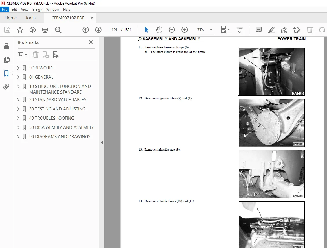
Rear Axle 1652
Removal 1652
Installation 1658
Axle Housing 1660
Disassembly 1660
Assembly 1665
Differential 1672
Disassembly 1673
Assembly 1681
BRAKE SYSTEM 1696
Parking Brake Disc And Plate 1696
Removal 1696
Installation 1699
UNDERCARRIAGE AND FRAME 1700
Center Hinge Pin 1700
Removal 1700
Installation 1705
Counterweight 1710
Removal 1710
Installation 1712
HYDRAULIC SYSTEM 1713
Steering Demand Valve 1713
Removal 1713
Installation 1716
Work Equipment Valve 1717
Removal 1717
Installation 1720
Brake Charge Valve 1721
Removal 1721
Installation 1721
Hydraulic Tank 1722
Removal 1722
Installation 1724
Steering And Power Train Pump 1725
Removal 1725
Installation 1725
Work Equipment And Cooling Fan Pump 1726
Removal 1726
Installation 1727
Hydraulic Cylinder 1728
Disassembly 1729
Assembly 1732
WORK EQUIPMENT 1738
Removal 1738
Installation 1741
CAB AND ITS ATTACHMENTS 1743
Operator’s Cab And Floor Frame 1743
Removal 1743
Installation 1747
Operator’s Cab Glass (Stuck Glass) 1748
Removal 1748
Installation 1750
Operator’s Seat 1758
Disassembly 1758
Assembly 1765
Manufactured By GRAMMER (Seat) 1770
Upper seat 1770
Suspension 1778
Air Conditioner Unit 1810
Removal 1810
Engine Controller 1816
Removal 1816
Installation 1816
Transmission Controller 1817
Removal 1817
Installation 1817
KOMTRAX Terminal 1818
Removal 1818
Installation 1818
90 DIAGRAMS AND DRAWINGS 1819
100 HYDRAULIC DIAGRAMS AND DRAWINGS 1819
POWER TRAIN HYDRAULIC CIRCUIT DIAGRAM – WITHOUT LOOKUP CLUTCH 1820
POWER TRAIN HYDRAULIC DIAGRAM – WITH LOOKUP CLUTCH 1821
AUTOMATIC GREASING CIRCUIT DIAGRAM 1822
AUTOMATIC GREASING CITCUIT DIAGRAM ASSEMBLY / PARTS 1823
HYDRAULIC CIRCUIT DIAGRAM 1825
200 ELECTRICAL DIAGRAMS AND DRAWINGS 1829
ELECTRICAL CIRCUIT DIAGRAM (1/10) 1831
ELECTRICAL CIRCUIT DIAGRAM (2/10) 1833
ELECTRICAL CIRCUIT DIAGRAM (3/10) 1835
ELECTRICAL CIRCUIT DIAGRAM (4/10) 1837
ELECTRICAL CIRCUIT DIAGRAM 5/10) 1839
ELECTRICAL CIRCUIT DIAGRAM (6/10) 1841
ELECTRICAL CIRCUIT DIAGRAM (7/10) 1843
ELECTRICAL CIRCUIT DIAGRAM (8/10) 1845
ELECTRICAL CIRCUIT DIAGRAM (9/10) 1847
ELECTRICAL CIRCUIT DIAGRAM (10/10) 1849
WORK EQUIPMENT CONTROLLER SYSTEM ELECTRICAL CIRCUIT DIAGRAM 1851
CONECTOR LIST AND STEREOGRAM 1853
S.V 15/12/24


