Komatsu WA380-6,WA380Z-6 Wheel Loader Shop Manual SEN06411-15 PDF
$36.95
Komatsu WA380-6,WA380Z-6 Wheel Loader Shop Manual SEN06411-15 – PDF DOWNLOAD
SERIAL NUMBERS
- WA380- 65001 and up
- WA380Z-66847 and up
Description
Komatsu WA380-6,WA380Z-6 Wheel Loader Shop Manual SEN06411-15 – PDF DOWNLOAD
FILE DETAILS:
Komatsu WA380-6,WA380Z-6 Wheel Loader Shop Manual SEN06411-15 – PDF DOWNLOAD
Language : English
Pages : 2174
Downloadable : Yes
File Type : PDF
IMAGES PREVIEW OF THE MANUAL:
TABLE OF CONTENTS:
Komatsu WA380-6,WA380Z-6 Wheel Loader Shop Manual SEN06411-15 – PDF DOWNLOAD
SERIAL NUMBERS
- WA380- 65001 and up
- WA380Z-66847 and up
Cover 1
00 Index and foreword 3
Index 3
Composition of shop manual . 4
Table of contents 6
Foreword and general information . 19
Safety notice 20
How to read the shop manual 25
Explanation of terms for maintenance standard 27
Handling of electric equipment and hydraulic component . 29
Handling of connectors newly used for engines 38
How to read electric wire code . 41
Precautions when carrying out operation 44
Method of disassembling and connecting push-pull type coupler 47
Standard tightening torque table . 50
Conversion table . 54
01 Specification . 61
Specification and technical data . 61
Specification dimension drawing 62
Specifications . 64
Weight table . 72
Table of fuel, coolant and lubricants 76
10 Structure, function and maintenance standard 79
Engine and cooling system 79
Engine mount and transmission mount 80
Cooling system . 81
Cooling fan pump . 83
Brake and fan pump . 90
Cooling fan motor 91
Power train 105
Power train 107
Power train system diagram . 108
Drive shaft 111
Power train piping diagram . 112
Torque converter . 114
Transmission . 122
Flow control valve . 156
Valve assembly . 158
ECMV . 159
Main relief valve and torque converter relief valve 167
Axle . 169
Differential . 176
Limited slip differential 183
Final drive 191
Steering system 197
Steering piping diagram 198
Steering column 200
Steering pump 202
Steering valve . 222
Orbit-roll valve . 237
Stop valve . 245
Steering relief valve 246
Steering cylinder 247
Emergency steering motor . 249
Emergency steering pump 250
Joystick steering lever linkage 251
Steering electric lever 252
Joystick EPC valve . 253
Brake system . 255
Brake piping diagram . 256
Charge valve . 258
Brake valve 265
Accumulator (for brake) 270
Brake 272
Parking brake control 277
Parking brake 278
Parking brake solenoid valve . 280
Emergency parking brake release valve 282
Undercarriage and frame 285
Axle mount and center hinge pin 286
Tires 291
Hydraulic system, Part 1 . 293
Hydraulic piping diagram . 294
Work equipment control lever linkage . 300
Hydraulic tank . 303
Power train pump . 307
Work equipment pump 308
Work equipment control valve . 330
CLSS . 358
Each function and operation of each valve 362
Hydraulic system, Part 2 . 395
PPC valve 396
Stabilizer valve . 402
Accumulator (for PPC circuit) 408
Accumulator (for ECSS) . 409
Work equipment PPC cut-off solenoid valve 410
Work equipment . 413
Work equipment linkage . 414
Bucket . 418
Bucket positioner and boom kick-out 420
Work equipment cylinder 426
Cab and its attachments 429
Cab 431
Air conditioner 432
Electrical system, Part 1 453
Machine monitor system . 454
Machine monitor 462
Electrical system, Part 2 521
Electrical system (Transmission controller system) . 522
Transmission controller 566
Electrical system (Work equipment controller system) . 570
Work equipment controller 576
Electrical system, Part 3 579
Electric transmission control 580
Kickdown switch and hold switch 584
Multi-function knob 586
Joystick steering knob . 587
KOMTRAX terminal system 588
Engine starting circuit 590
Engine stopping circuit 594
Preheating circuit . 596
Engine power mode selector circuit . 597
Engine output derating function 598
Automatic warm-up function . 598
Parking brake circuit 600
Sensor . 602
20 Standard value table 613
Standard service value table . 613
Standard service value table for engine 614
Standard service value table for chassis . 616
30 Testing and adjusting . 629
Testing and adjusting, Part 1 629
Precautions before work 631
Tools for testing, adjusting, and troubleshooting 632
Testing engine speed . 639
Testing exhaust gas color 641
Adjusting valve clearance 643
Testing compression pressure . 648
Testing blow-by pressure . 654
Testing engine oil pressure 655
Testing intake air (boost) pressure 657
Handling fuel system equipment . 659
Releasing residual pressure in fuel system . 659
Testing fuel pressure 660
Testing fuel delivery, return and leak amount 665
Bleeding air from fuel circuit . 673
Testing leakage in fuel system . 675
Handling reduced cylinder mode operation . 676
Handling no-injection cranking operation . 676
Handling controller voltage circuit 677
Testing muffler (main body) and muffler stack for looseness or damage 677
Testing muffler for functions 678
Testing cylinder head and manifold parts for tightness . 678
Testing engine piping for damage and tightness . 679
Testing and replacing alternator belt 680
Testing and replacing auto-tensioner . 683
Adjusting transmission speed sensor 686
Adjusting length of directional lever 687
Adjusting length of gearshift lever 687
Testing directional lever 688
Testing and adjusting power train oil pressure . 689
Procedure for flushing torque converter and transmission hydraulic circuit . 718
Method of moving machine when transmission valve is broken . 719
Testing axle end for oil leakage . 723
Testing drive shaft for looseness, backlash and damage . 723
Testing and adjusting steering stop valve 724
Testing and adjusting steering wheel . 726
Testing and adjusting steering oil pressure 728
Bleeding air from steering circuit . 731
Testing and adjusting, Part 2 733
Testing hydraulic drive fan 735
Bleeding air from hydraulic drive fan circuit 739
Testing brake pedal 742
Testing and adjusting brake pedal linkage 743
Testing brake performance 744
Measuring accumulator nitrogen gas pressure and charging procedure for accumulator nitrogen gas 745
Testing and adjusting accumulator charge pressure 751
Testing wheel brake oil pressure . 753
Testing wheel brake oil pressure drop 754
Testing wear of wheel brake disc . 756
Bleeding air from wheel brake circuit 757
Releasing residual pressure in brake accumulator circuit . 758
Testing parking brake performance 759
Testing parking brake oil pressure . 760
Testing wear of parking brake disc . 762
Method of releasing parking brake manually . 763
Testing and adjusting work equipment control lever . 764
Testing and adjusting work equipment PPC oil pressure 765
Testing and adjusting work equipment oil pressure 771
Bleeding air from work equipment circuit . 775
Releasing residual pressure in work equipment circuit 776
Procedure for testing of nitrogen gas pressure and charging of nitrogen gas of ECSS (Electronically Controlled Suspension System) accumulator 778
Testing and adjusting bucket positioner 782
Testing and adjusting boom kick-out 784
Checking proximity switch operation pilot lamp . 785
Procedure for testing diodes . 786
Preparation work for troubleshooting for electric system . 787
How to start operation of KOMTRAX terminal . 796
Lamp display of KOMTRAX terminal . 801
Testing and adjusting, Part 3 805
Adjusting replaced, reassembled or added sensor, controller, etc. with machine monitor . 807
Special functions of machine monitor (EMMS) 809
Pm-clinic inspection table . 878
40 Troubleshooting . 885
Failure code table and fuse locations 885
Precautions before work 886
Failure code table . 887
Fuse locations . 904
General information on troubleshooting . 911
Points to remember when troubleshooting 912
Sequence of events in troubleshooting 913
Testing before troubleshooting . 915
Classification and procedures of troubleshooting . 916
Information contained in troubleshooting table . 919
Connection table for connector pin numbers . 921
T- branch box and T- branch adapter table 957
Troubleshooting by failure code (Display of code), Part 1 961
Failure code [1500L0] (TORQFLOW transmission: Double meshing) 963
Failure code [15SAL1] (ECMV F clutch: When command current is OFF, fill signal is ON) 964
Failure code [15SALH] (ECMV F clutch: When command current is ON, fill signal is OFF) 966
Failure code [15SBL1] (ECMV R clutch: When command current is OFF, fill signal is ON) 968
Failure code [15SBLH] (ECMV R clutch: When command current is ON, fill signal is OFF) 970
Failure code [15SEL1] (ECMV 1st clutch: When command current is OFF, fill signal is ON) 972
Failure code [15SELH] (ECMV 1st clutch: When command current is ON, fill signal is OFF) 974
Failure code [15SFL1] (ECMV 2nd clutch: When command current is OFF, fill signal is ON) 976
Failure code [15SFLH] (ECMV 2nd clutch: When command current is ON, fill signal is OFF) 978
Failure code [15SGL1] (ECMV 3rd clutch: When command current is OFF, fill signal is ON) 980
Failure code [15SGLH] (ECMV 3rd clutch: When command current is ON, fill signal is OFF) 982
Failure code [15SHL1] (ECMV 4th clutch: When command current is OFF, fill signal is ON) 984
Failure code [15SHLH] (ECMV 4th clutch: When command current is ON, fill signal is OFF) 986
Failure code [2F00MA] (Parking brake: Malfunction) . 988
Failure code [2G43ZG] (Accumulator: Low oil pressure) 991
Failure code [44K0L4] (Bucket positioner: ON/OFF signals disagree) . 995
Troubleshooting by failure code (Display of code), Part 2 999
Failure code [AA1ANX] (Air cleaner: Clogging) 1002
Failure code [AB00L6] (Alternator: Signal disagrees with operating state of engine) 1005
Failure code [AB00MA] (Alternator: Malfunction) 1009
Failure code [B@BAZG] (Rotation derating by low engine oil pressure) .1013
Failure code [B@BAZK] (Engine oil: Low level) 1014
Failure code [B@BCNS] (Coolant: Overheating) .1015
Failure code [B@BCZK] (Coolant: Low level) .1017
Failure code [B@BEBF] (Water in fuel error) 1020
Failure code [B@C7NS] (High Brake Oil Temp) 1022
Failure code [b@CENS] (Torque converter oil: Overheating) 1024
Failure code [B@CENS] (Torque converter oil: Overheating) 1027
Failure code [B@HANS] (Hydraulic oil: Overheating) .1030
Failure code [CA111] (Abnormality in engine controller) 1032
Failure code [CA115] (Engine Ne or Bkup speed sensor error) 1033
Failure code [CA122] (Charge pressure sensor high error) .1034
Failure code [CA123] (Charge pressure sensor low error) 1036
Failure code [CA131] (Throttle sensor high error) 1038
Failure code [CA132] (Throttle sensor low error) .1040
Failure code [CA144] (Coolant sensor high error) .1042
Failure code [CA145] (Coolant sensor low error) 1044
Failure code [CA153] (Charge temperature sensor high error) 1046
Failure code [CA154] (Charge temperature sensor low error) .1048
Failure code [CA155] (Derating of speed by abnormally high charge temperature) .1050
Failure code [CA187] (Sensor power supply 2 low error) .1052
Failure code [CA221] (Atmospheric pressure sensor high error) 1054
Failure code [CA222] (Atmospheric sensor low error) 1056
Failure code [CA227] (Sensor power supply 2 high error) 1058
Failure code [CA234] (Engine overspeed) 1059
Failure code [CA238] (Ne speed sensor power supply error) 1060
Troubleshooting by failure code (Display of code), Part 3 1063
Failure code [CA271] (IMV/PCV1 Short circuit) 1065
Failure code [CA272] (IMV/PCV1 Disconnection) 1066
Failure code [CA322] (Injector #1 open/short error) 1068
Failure code [CA323] (Injector #5 open/short error) 1070
Failure code [CA324] (Injector #3 open/short error) 1072
Failure code [CA325] (Injector #6 open/short error) 1074
Failure code [CA331] (Injector #2 open/short error) 1076
Failure code [CA332] (Injector #4 open/short error) 1078
Failure code [CA342] (Calibration code inconsistency) 1080
Failure code [CA351] (Injectors drive circuit error) .1082
Failure code [CA352] (Sensor power supply 1 low error) .1085
Failure code [CA386] (Sensor power supply 1 high error) 1087
Failure code [CA428] (Abnormally high level in water sensor) .1088
Failure code [CA429] (Abnormally low level in water sensor) 1089
Failure code [CA431] (Idle validation switch error) 1090
Failure code [CA432] (Idle validation action error) 1093
Failure code [CA435] (Engine oil pressure switch error) 1095
Failure code [CA441] (Battery voltage low error) .1096
Failure code [CA442] (Battery voltage high error) 1100
Failure code [CA449] Common rail pressure high error 2 .1103
Failure code [CA451] (Common rail pressure sensor high error) 1105
Failure code [CA452] (Common rail pressure sensor low error) .1107
Failure code [CA488] (Derating of torque by abnormally high charge temperature) 1109
Failure code [CA553] (Common rail pressure high error 1) .1110
Failure code [CA559] (Supply pump pressure very low error) .1111
Failure code [CA689] (Engine Ne speed sensor error) 1112
Failure code [CA731] (Engine Bkup speed sensor phase error) 1115
Failure code [CA757] (All continuous data lost error) 1116
Failure code [CA778] (Engine Bkup speed sensor error) 1120
Failure code [CA1633] (KOMNET datalink timeout error) 1123
Failure code [CA2185] (Throttle sensor power supply voltage high error) 1129
Failure code [CA2186] (Throttle sensor power supply voltage low error) .1130
Troubleshooting by failure code (Display of code), Part 4 1133
Failure code [CA2249] (Supply pump pressure very low error 2) 1135
Failure code [CA2311] (Abnormality in IMV solenoid) 1136
Failure code [CA2555] (Intake heater relay disconnection error) 1138
Failure code [CA2556] (Intake heater relay short circuit error) 1141
Failure code [D150KA] (Emergency steering relay: Disconnection) 1144
Failure code [D150KB] (Emergency steering relay: Short circuit) 1147
Failure code [D150KY] (Emergency steering relay: Short circuit with power supply line) .1150
Failure code [D160KA] (Backup lamp relay: Disconnection) .1153
Failure code [D160KB] (Backup lamp relay: Short circuit) .1156
Failure code [D191KA] (Joystick steering neutral safety relay: Disconnection) 1159
Failure code [D191KB] (Joystick steering neutral safety relay: Short circuit) 1161
Failure code [D191KY] (Joystick steering neutral safety relay: Short circuit with power supply line) .1163
Failure code [D192KA] (ECSS solenoid: Disconnection) .1165
Failure code [D192KB] (ECSS solenoid: Short circuit) .1166
Failure code [D192KY] (ECSS solenoid: Short circuit with power supply line) 1167
Failure code [D193KA] (Joystick steering solenoid cut relay: Disconnection) 1168
Failure code [D193KB] (Joystick steering solenoid cut relay: Short circuit) 1170
Failure code [D193KY] (Joystick steering solenoid cut relay: Short circuit with power supply line) .1172
Failure code [D5ZHKA] (Terminal C signal: Disconnection) .1175
Failure code [D5ZHKB] (Terminal C signal: Short circuit) .1181
Failure code [D5ZHKZ] (Terminal C signal: Disconnection or short circuit) 1186
Failure code [D5ZHL6] (Terminal C signal: Signal does not match engine running or stopped state) .1193
Failure code [DA80L4] (Auto grease controller: ON/OFF signals disagree) 1198
Failure code [DAF3KK] (Machine monitor: Low source voltage (input) .1200
Failure code [DAF5KP] (Machine monitor: Low output voltage) 1204
Failure code [DAFRKR] (CAN communication with machine monitor: Defective communication (Abnormality in target component system) 1208
Troubleshooting by failure code (Display of code), Part 5 1213
Failure code [DAQ0KK] (Transmission controller: Low source voltage) 1216
Failure code [DAQ0KT] (Transmission controller: Abnormality in controller) .1220
Failure code [DAQ2KK] (Transmission controller load power supply line: Low source voltage (input) 1221
Failure code [DAQ9KQ] (Transmission controller model selection: Disagreement of model selection signals) .1224
Failure code [DAQRKR] (CAN communication with transmission controller: Defective communication (Abnormality in target component system) 1225
Failure code [DAQRMA] (Transmission controller option setting: Malfunction) 1231
Failure code [DB2RKR] (CAN communication with engine controller: Defective communication (Abnormality in target component system) 1232
Failure code [DB90KK] Work equipment controller: Low source voltage (input) 1236
Failure code [DB90KT] Work equipment controller: Abnormality in controller .1238
Failure code [DB92KK] Work equipment controller load power supply line: Low source voltage (input) .1239
Failure code [DB95KX] Work equipment controller power supply output: Out of input signal range .1241
Failure code [DB99KQ] (Work equipment controller model selection: Disagreement in model selection signals) .1244
Failure code [DB9RKR] CAN communication with work equipment controller: Defective communication (Abnormality in target component system) .1245
Failure code [DB9RMA] (Work equipment controller option setting: Malfunction) 1247
Failure code [DB9RMC] (CAN communication with transmission controller, engine controller and machine monitor: Defective operation) .1248
Failure code [DD15LD] t switch (Panel switch 1): Switch is kept pressed for long time 1252
Failure code [DD16LD] U switch (Panel switch 2): Switch is kept pressed for long time 1255
Failure code [DD17LD] < switch (Panel switch 3): Switch is kept pressed for long time 1258
Failure code [DD18LD] > switch (Panel switch 4): Switch is kept pressed for long time 1261
Failure code [DD1ALD] Remote positioner raise/lower set switch (raise): Switch is kept pressed for long time .1264
Failure code [DD1BLD] Remote positioner raise/lower set switch (lower): Switch is kept pressed for long time .1266
Failure code [DD1CLD] Load meter subtotal switch: Switch is kept pressed for long time .1268
Failure code [DD1FLD] Load meter mode selector switch (A/B): Switch is kept pressed for long time 1270
Failure code [DD1GLD] Load meter mode selector switch (+/–): Switch is kept pressed for long time 1272
Failure code [DD1HLD] (Load meter display selector switch: Switch is kept pressed for long time) .1274
Failure code [DD1NLD] (Fan reverse switch: Switch is kept pressed for long time) .1276
Failure code [DD1NL4] (Fan automatic reverse switch: Switch is kept pressed for long time) .1278
Failure code [DDB6L4] (Parking brake switch (Neutralizer): ON/OFF signals disagree) 1280
Troubleshooting by failure code (Display of code), Part 6 1285
Failure code [DDE5MA] (Emergency steering drive switch: Malfunction) .1288
Failure code [DDK3KA] (Right FNR switch: Disconnection) 1291
Failure code [DDK4KA] (Joystick steering FNR switch: Disconnection) 1294
Failure code [DDK5L4] (Joystick steering shift-up/down switch: ON/OFF signals disagree) 1297
Failure code [DDK6KA] (FNR lever switch: Disconnection) 1299
Failure code [DDK6KB] (FNR lever switch: Short circuit) 1306
Failure code [DDS5KA] (Steering pressure switch: Disconnected) .1310
Failure code [DDS5KB] (Steering pressure switch: Grounded) .1312
Failure code [DDT0L4] (Shift mode selector switch: ON/OFF signals disagree) 1314
Failure code [DDT4LD] (Transmission cut-off set switch: Switch is kept pressed for long time) 1317
Failure code [DDW9LD] (Kick-down switch: Switch is kept pressed for long time) .1320
Failure code [DDWLLD] (Hold switch: Switch is kept pressed for long time) 1323
Failure code [DDY0LD] (Load meter cancel switch: Switch is kept pressed for long time) .1326
Failure code [DF10KA] (Transmission shift lever switch: Disconnected) 1328
Failure code [DF10KB] (Transmission shift lever switch: Short circuit) .1332
Failure code [DGF1KA] (Transmission oil temperature sensor: Disconnected) 1335
Failure code [DGF1KB] (Transmission oil temperature sensor: Short circuit) .1338
Failure code [DGH2KX] (Hydraulic oil temperature sensor: Out of input signal range) 1341
Failure code [DGR2KA] (Rear brake oil temperature sensor: Disconnected) 1343
Failure code [DGR2KX] (Rear brake oil temperature sensor: Out of input signal range) .1345
Failure code [DGT1KX] (Torque converter oil temperature sensor: Out of input signal range) .1347
Failure code [DH21KA] (Loader pump pressure sensor: Disconnection) .1350
Failure code [DH21KB] (Loader pump pressure sensor: Power supply line short) .1352
Troubleshooting by failure code (Display of code), Part 7 1355
Failure code [DHPCKX] (Lift arm cylinder bottom pressure sensor: Out of input signal range) 1358
Failure code [DHPDKX] (Lift arm cylinder head pressure sensor: Out of input signal range) 1360
Failure code [DHT1KX] (Transmission cut-off pressure sensor: Out of input signal range) 1362
Failure code [DHT8KA] (Steering pump pressure sensor: Disconnection) .1366
Failure code [DHT8KB] (Steering pump pressure sensor: Short circuit) .1368
Failure code [DK59KA] (Lift arm EPC lever potentiometer (Main): Disconnection) .1370
Failure code [DK59KY] (Lift arm EPC lever potentiometer (Main): Short circuit with power supply line) 1373
Failure code [DK59L8] (Lift arm EPC lever potentiometer (Main): Analog signals disagree) .1376
Failure code [DK5AKA] (Lift arm EPC lever potentiometer (Sub): Disconnection) 1379
Failure code [DK5AKY] (Lift arm EPC lever potentiometer (Sub): Short circuit with power supply line) .1382
Failure code [DK5BKA] (Bucket EPC lever potentiometer (Main): Disconnection) .1385
Failure code [DK5BKY] (Bucket EPC lever potentiometer (Main): Short circuit with power supply line) 1388
Failure code [DK5BL8] (Bucket EPC lever potentiometer (Main): Analog signals disagree) .1391
Failure code [DK5CKA] (Bucket EPC lever potentiometer (Sub): Disconnection) 1394
Failure code [DK5CKY] (Bucket EPC lever potentiometer (Sub): Short circuit with power supply line) .1397
Troubleshooting by failure code (Display of code), Part 8 1401
Failure code [DK5FKA] (Joystick steering EPC lever potentiometer (Main): Disconnection) 1403
Failure code [DK5FKY] (Joystick steering EPC lever potentiometer (Main): Short circuit with power supply line) .1406
Failure code [DK5GKA] (Joystick steering EPC lever potentiometer (Sub): Disconnection) .1408
Failure code [DK5GKY] (Joystick steering EPC lever potentiometer (Sub): Short circuit with power supply line) 1412
Failure code [DK5FL8] (Joystick steering EPC lever potentiometer (Main): Analog signals disagree) 1414
Failure code [DKA0KA] (Lift arm angle sensor: Disconnection) .1418
Failure code [DKA0KX] (Lift arm angle sensor: Out of input signal range) .1420
Failure code [DKA0KY] (Lift arm angle sensor: Short circuit with power supply line) 1422
Failure code [DKA0L0] (Lift arm angle sensor: Dislocation of sensor) .1424
Failure code [DLT3KA] (Transmission output shaft speed sensor: Disconnection) 1426
Failure code [DLT3LC] (Transmission output shaft speed sensor: Out of input signal range) 1428
Failure code [DT20KB] (Transmission cut-off indicator lamp: Short circuit) .1430
Failure code [DUM1KB] (Remote positioner raise set indicator lamp: Short circuit) 1434
Failure code [DUM2KB] (Remote positioner lower set indicator lamp: Short circuit) 1436
Failure code [DV00KB] (Alarm buzzer: Short circuit) 1438
Failure code [DW4PKA] (Lift arm raise EPC solenoid: Disconnection) .1440
Failure code [DW4PKB] (Lift arm raise EPC solenoid: Short circuit) .1442
Failure code [DW4PKY] (Lift arm raise EPC solenoid: Short circuit with power supply line) 1444
Failure code [DW4QKA] (Lift arm lower EPC solenoid: Disconnection) .1446
Failure code [DW4QKB] (Lift arm lower EPC solenoid: Short circuit) .1447
Failure code [DW4QKY] (Lift arm lower EPC solenoid: Short circuit with power supply line) 1448
Failure code [DW4RKA] (Bucket tilt EPC solenoid: Disconnection) 1450
Failure code [DW4RKB] (Bucket tilt EPC solenoid: Short circuit) 1451
Failure code [DW4RKY] (Bucket tilt EPC solenoid: Short circuit with power supply line) .1452
Troubleshooting by failure code (Display of code), Part 9 1455
Failure code [DW4SKA] (Bucket dump EPC solenoid: Disconnection) 1457
Failure code [DW4SKB] (Bucket dump EPC solenoid: Short circuit) 1458
Failure code [DW4SKY] (Bucket dump EPC solenoid: Short circuit with power supply line) .1460
Failure code [DW7BKA] (Fan reverse solenoid: Disconnection) 1462
Failure code [DW7BKB] (Fan reverse solenoid: Short circuit) 1464
Failure code [DW7BKY] (Fan reverse solenoid: Short circuit with power supply line) .1466
Failure code [DWM1KA] (Work equipment neutral lock solenoid: Disconnection) 1468
Failure code [DWM1KB] (Work equipment neutral lock solenoid: Short circuit) 1470
Failure code [DWM1KY] (Work equipment neutral lock solenoid: Short circuit with power supply line) .1472
Failure code [DWN6KA] (Lift arm raise magnet detent solenoid: Disconnection) .1474
Failure code [DWN6KB] (Lift arm raise magnet detent solenoid: Short circuit) .1476
Failure code [DWN6KY] (Lift arm raise magnet detent solenoid: Short circuit with power supply line) 1478
Failure code [DWN7KA] (Lift arm float magnet detent solenoid: Disconnection) .1480
Failure code [DWN7KB] (Lift arm float magnet detent solenoid: Short circuit) .1482
Failure code [DWN7KY] (Lift arm float magnet detent solenoid: Short circuit with power supply line) 1484
Failure code [DWN8KA] (Bucket tilt magnet detent solenoid: Disconnection) 1486
Failure code [DWN8KB] (Bucket tilt magnet detent solenoid: Short circuit) 1488
Failure code [DWN8KY] (Bucket tilt magnet detent solenoid: Shorted with the power source) 1490
Failure code [DX16KA] (Fan pump EPC solenoid: Disconnection) (WA380-6) .1492
Failure code [DX16KA] (Fan motor EPC solenoid: Disconnection) (WA380Z-6) .1493
Failure code [DX16KB] (Fan pump EPC solenoid: Short circuit) (WA380-6) .1494
Failure code [DX16KB] (Fan motor EPC solenoid: Short circuit) (WA380Z-6) .1495
Failure code [DX16KY] (Fan motor EPC solenoid: Short circuit with power supply line) (WA380Z-6) 1497
Failure code [DXA1KA] (Loader pump EPC solenoid: Disconnection) 1498
Failure code [DXA1KB] (Loader pump EPC solenoid: Short circuit) 1500
Failure code [DXH1KA] (Lockup ECMV solenoid: Disconnection) 1502
Failure code [DXH1KB] (Lockup ECMV solenoid: Short circuit) 1504
Failure code [DXH1KY] (Lockup ECMV solenoid: Short circuit with power supply line) .1506
Failure code [DXH4KA] (1st clutch ECMV solenoid: Disconnection) 1508
Failure code [DXH4KB] (1st clutch ECMV solenoid: Short circuit) 1510
Failure code [DXH4KY] (1st clutch ECMV solenoid: Short circuit with power supply line) .1512
Troubleshooting by failure code (Display of code), Part 10 .1515
Failure code [DXH5KA] (2nd clutch ECMV solenoid: Disconnection) 1518
Failure code [DXH5KB] (2nd clutch ECMV solenoid: Short circuit) 1520
Failure code [DXH5KY] (2nd clutch ECMV solenoid: Short circuit with power supply line) .1522
Failure code [DXH6KA] (3rd clutch ECMV solenoid: Disconnection) 1524
Failure code [DXH6KB] (3rd clutch ECMV solenoid: Short circuit) 1526
Failure code [DXH6KY] (3rd clutch ECMV solenoid: Short circuit with power supply line) .1528
Failure code [DXH7KA] (R clutch ECMV solenoid: Disconnection) 1530
Failure code [DXH7KB] (R clutch ECMV solenoid: Short circuit) 1532
Failure code [DXH7KY] (R clutch ECMV solenoid: Short circuit with power supply line) .1534
Failure code [DXH8KA] (F clutch ECMV solenoid: Disconnection) 1536
Failure code [DXH8KB] (F clutch ECMV solenoid: Short circuit) 1538
Failure code [DXH8KY] (F clutch ECMV solenoid: Short circuit with power supply line) .1540
Failure code [DXHHKA] (4th clutch ECMV solenoid: Disconnection) 1542
Failure code [DXHHKB] (4th clutch ECMV solenoid: Short circuit) 1544
Failure code [DXHHKY] (4th clutch ECMV solenoid: Short circuit with power supply line) .1546
Failure code [DXHLKA] (Joystick steering right EPC solenoid: Disconnection) 1548
Failure code [DXHLKB] (Joystick steering right EPC solenoid: Short circuit) 1550
Failure code [DXHLKY] (Joystick steering right EPC solenoid: Short circuit with power supply line) .1552
Failure code [DXHMKA] (Joystick steering left EPC solenoid: Disconnection) .1554
Failure code [DXHMKB] (Joystick steering left EPC solenoid: Short circuit) .1556
Failure code [DXHMKY] (Joystick steering left EPC solenoid: Short circuit with power supply line) 1558
Failure code [DY30MA] Motor-driven emergency steering pump failure (During operation of machine) .1560
Failure code [DY30MC] Motor-driven emergency steering pump failure (Malfunction in manual mode) 1565
Troubleshooting of electrical system (E-mode) 1573
Installing positions of fuses 1575
Information in troubleshooting table .1580
E-1 Engine does not start 1581
E-2 Wiper does not operate .1594
E-3 Windshield washer does not operate .1599
E-4 Headlamp, clearance lamp, tail lamp, and license lamp do not light up or go off 1603
E-5 Working lamp does not light up or go off .1619
E-6 Turn signal lamp and hazard lamp do not light up or go off .1629
E-7 Brake lamp does not light or it keeps lighting up 1641
E-8 Backup lamp does not light or it keeps lighting up .1645
E-9 Backup buzzer does not sound or it keeps sounding 1649
E-10 Horn does not sound or it keeps sounding 1652
E-11 Alarm buzzer does not sound or it keeps sounding 1656
E-12 Air conditioner does not operate or stop 1658
E-13 The KOMTRAX system does not work properly .1662
E-14 When kick-down switch is turned ON, kick-down operation does not start 1665
E-15 When hold switch is pressed, holding operation does not start .1668
E-16 Transmission is kept in neutral, or brake drags when directional lever is operated while parking brake is applied .1671
E-17 Transmission cut-off mode cannot be set or reset 1674
E-18 Transmission cut-off set cannot be reset 1677
E-19 FNR switch mode cannot be set or reset 1680
E-20 Fan reverse function cannot be used or reset 1682
E-21 Discharge from loader pump does not rise from minimum level .1684
E-22 ECSS function cannot be used or reset .1686
E-23 When parking brake is turned ON, parking brake indicator lamp does not light up .1688
E-24 When emergency brake operates, brake oil pressure caution lamp does not operate .1692
E-25 Air cleaner clogging indicator lamp does not light up .1696
E-26 Radiator coolant level caution lamp does not light up .1699
E-27 Hydraulic oil temperature gauge does not rise and hydraulic oil temperature caution lamp does not light up 1701
E-28 Torque converter oil temperature gauge does not rise and torque converter oil temperature caution lamp does not light up 1703
E-29 Steering oil pressure caution lamp does not light up 1705
E-30 Abnormality in ■ switch (panel switch 1) input 1708
E-31 Abnormality in <> switch (panel switch 2) input .1711
名称未設定 1714
E-32 Abnormality in < switch (panel switch 3) input 1714
E-33 Abnormality in > switch (panel switch 4) input 1717
Troubleshooting of hydraulic and mechanical system (H-mode) 1721
Method of using troubleshooting chart 1723
Table of failure modes and causes 1726
H-1 The machine does not start .1734
H-2 Torque converter lockup is not switched off (engine stalls) [Machine with lockup clutch] .1736
H-3 Torque converter lockup is not switched on [Machine with lockup clutch] 1737
H-4 The travel speed is slow, the thrusting force is weak, the uphill traveling power is weak, and the gear is not shifted .1738
H-5 Shocks are large at the times of starting and shifting gear 1740
H-6 Time lag is large at the times of starting and shifting gear .1742
H-7 The torque converter oil temperature is high .1744
H-8 Steering does not turn .1745
H-9 Steering does not turn [Machine with joystick steering] 1746
H-10 Steering response is low 1747
H-11 Turning, response of steering is poor [machine with joystick steering] 1748
H-12 Steering is heavy .1749
H-13 When machine turns, it shakes or makes large shocks .1750
H-14 When machine turns, it shakes or makes large shocks [machine with joystick steering] 1751
H-15 The wheel brake does not work or does not work well .1752
H-16 The wheel brake is not released or it drags .1753
H-17 The parking brake does not work or does not work well .1754
H-18 The parking brake is not released or it drags (including emergency release system) 1755
H-19 Lift arm does not rise 1756
H-20 Lift arm speed is low or rising force of lift arm is insufficient .1757
H-21 When rising, the lift arm comes to move slowly at specific height .1758
H-22 The lift arm cylinder cannot hold down the bucket (Bucket floats) .1758
H-23 Hydraulic drifts of the lift arm is large .1758
H-24 The lift arm wobbles during operation .1758
H-25 Bucket does not tilt back .1759
H-26 Bucket speed is low or tilting back force is insufficient .1760
H-27 The bucket comes to operate slowly in the midst of tilting-back .1761
H-28 The bucket cylinder cannot hold down the bucket .1761
H-29 Hydraulic drifts of the bucket is large .1761
H-30 The bucket wobbles during travel with cargo (The work equipment valve is set to “HOLD”) .1761
H-31 Lift arm and bucket control levers do not move smoothly and are heavy .1762
H-32 During operation of the machine, engine speed lowers remarkably or engine stalls 1763
H-33 Large shock is made when work equipment starts and stops 1763
H-34 When work equipment circuit is relieved singly, other work equipment moves 1763
H-35 ECSS does not operate, and pitching, bouncing occur .1764
H-36 Fan revolution is abnormal (Fan sound/ vibration is abnormally large or engine overheats) .1765
Troubleshooting of engine (S-mode) .1767
Method of using troubleshooting charts .1769
S-1 Engine does not start easily .1772
S-2 Engine does not start 1773
S-3 Engine does not pick up smoothly .1776
S-4 Engine stops during operations .1777
S-5 Engine does not rotate smoothly 1778
S-6 Engine lacks output (or lacks power) .1779
S-7 Exhaust smoke is black (Incomplete combustion) .1780
S-8 Oil consumption is excessive (or exhaust smoke is blue) 1781
S-9 Engine oil becomes contaminated quickly 1782
S-10 Fuel consumption is excessive .1783
S-11 Coolant contains oil (blows back or reduces) 1784
S-12 Oil pressure drops 1785
S-13 Oil level rises (Water, fuel in oil) 1786
S-14 Coolant temperature rises too high (Overheating) 1787
S-15 Abnormal noise is made 1788
S-16 Vibration is excessive 1789
50 Disassembly and assembly 1791
General information on disassembly and assembly 1791
Precautions before work 1792
How to read this manual 1793
Coating materials list .1795
Special tools list .1798
Sketches of special tools 1801
Engine and cooling system 1809
Removal and installation of fuel supply pump assembly 1810
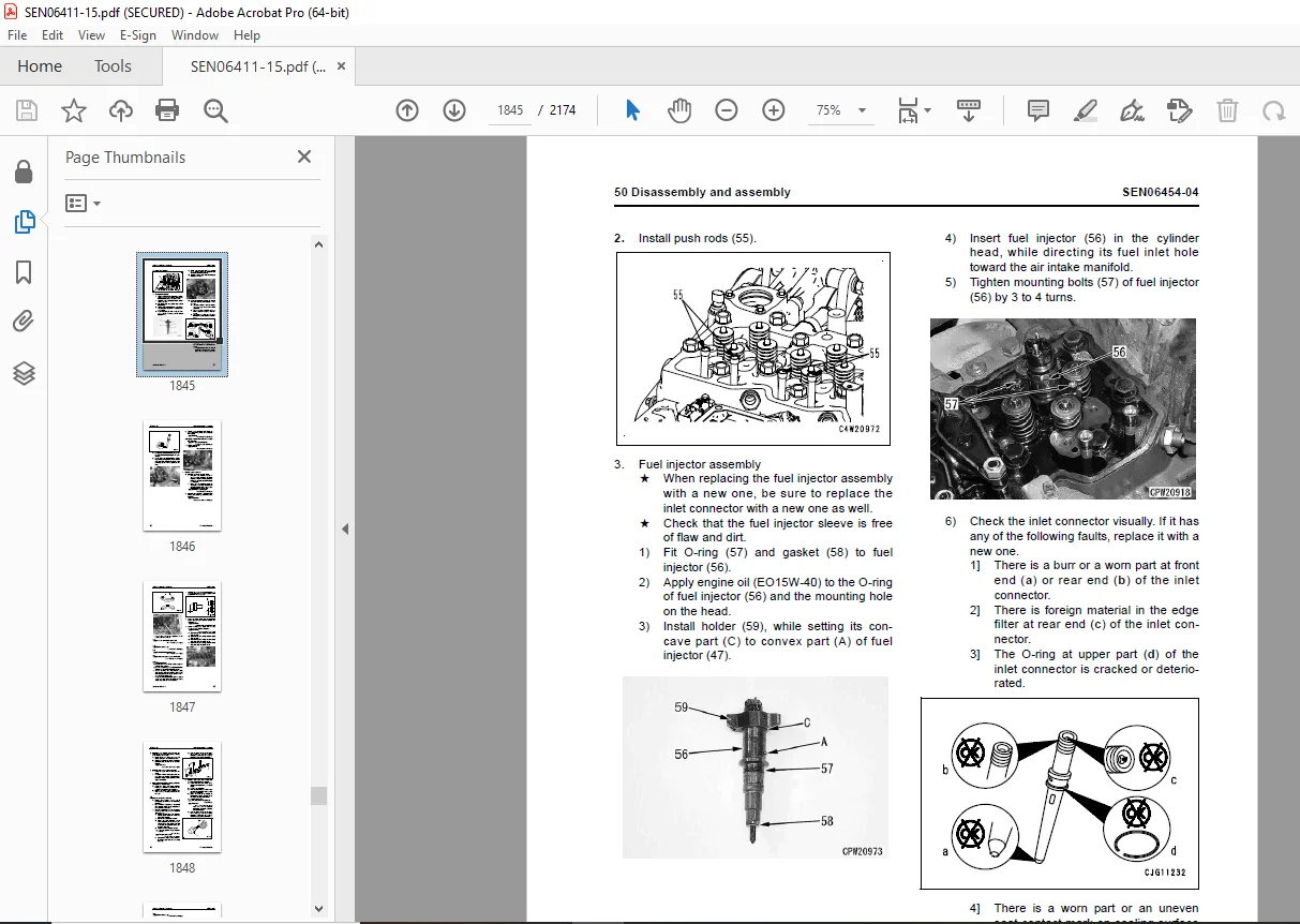
Removal and installation of fuel injector assembly .1814
Removal and installation of cylinder head assembly .1828
Removal and installation of engine hood assembly .1850
Removal and installation of radiator assembly 1855
Removal and installation of air aftercooler 1860
Power train 1885
Removal and installation of torque converter and transmission assembly .1886
Disassembly and assembly of torque converter assembly (Standard specification) .1892
Disassembly and assembly of torque converter assembly (Lockup specification) .1896
Disassembly and assembly of transmission assembly 1902
Disassembly and assembly of transmission clutch pack assembly 1919
Disassembly and assembly of parking brake assembly .1938
Removal and installation of front axle assembly 1947
Removal and installation of rear axle assembly .1949
Disassembly and assembly of axle housing .1953
Disassembly and assembly of differential assembly 1963
Steering system 1987
Removal and installation of steering valve assembly 1988
Removal and installation of steering valve oil seal 1992
Brake system .1995
Removal and installation of parking brake discs and plates .1996
Undercarriage and frame 2001
Removal and installation of center hinge pin .2002
Removal and installation of counterweight 2010
Hydraulic system .2015
Removal and installation of work equipment control valve assembly 2016
Removal and installation of power train pump and work equipment pump assembly 2022
Removal and installation of steering pump and cooling fan pump assembly 2023
Removal and installation of hydraulic tank assembly 2025
Work equipment .2029
Removal and installation of work equipment assembly 2030
Disassembly and assembly of hydraulic cylinder assembly 2034
Cab and its attachments 2043
Removal and installation of operator’s cab and floor frame assembly 2044
Removal and installation of operator’s cab glass (stuck glass) .2048
Disassembly and assembly of operator’s seat assembly (Standard specification) 2056
Disassembly and assembly of operator’s seat assembly (Manufactured by GRAMMER) .2065
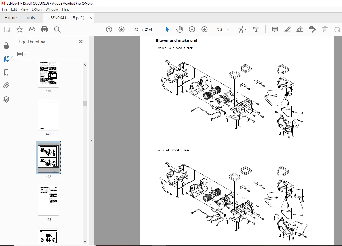
Removal and installation of air conditioner unit assembly 2098
Electrical system 2103
Removal and installation of engine controller assembly .2104
90 Diagrams and drawings .2107
Hydraulic diagrams and drawings 2107
Power train hydraulic circuit diagram 2108
Automatic greasing circuit diagram .2110
Hydraulic circuit diagram (WA380-6) 2113
Hydraulic circuit diagram (WA380Z-6) .2115
Electrical diagrams and drawings .2119
Electrical circuit diagram .2121
Work equipment controller system electrical circuit diagram 2167
Connector list and stereogram 2169
DESCRIPTION:
Komatsu WA380-6,WA380Z-6 Wheel Loader Shop Manual SEN06411-15 – PDF DOWNLOAD
SERIAL NUMBERS
- WA380- 65001 and up
- WA380Z-66847 and up
How to read the shop manual
1. Composition of shop manual
This shop manual contains the necessary technical information for services performed in a workshop.
For ease of understanding, the manual is divided into the following sections.
00. Index and foreword
This section explains the shop manuals list, table of contents, safety, and basic information.
01. Specification
This section explains the specifications of the machine.
10. Structure, function and maintenance standard
This section explains the structure, function, and maintenance standard values of each component.
The structure and function sub-section explains the structure and function of each component. It
serves not only to give an understanding of the structure, but also serves as reference material for
troubleshooting. The maintenance standard sub-section explains the criteria and remedies for disassembly
and service.
20. Standard value table
This section explains the standard values for new machine and judgement criteria for testing,
adjusting, and troubleshooting. This standard value table is used to check the standard values in
testing and adjusting and to judge parts in troubleshooting.
30. Testing and adjusting
This section explains measuring instruments and measuring methods for testing and adjusting, and
method of adjusting each part. The standard values and judgement criteria for testing and adjusting
are explained in Testing and adjusting.
40. Troubleshooting
This section explains how to find out failed parts and how to repair them. The troubleshooting is
divided by failure modes. The “S mode” of the troubleshooting related to the engine may be also
explained in the Chassis volume and Engine volume. In this case, see the Chassis volume.
50. Disassembly and assembly
This section explains the special tools and procedures for removing, installing, disassembling, and
assembling each component, as well as precautions for them. In addition, tightening torque and
quantity and weight of coating material, oil, grease, and coolant necessary for the work are also
explained.
90. Diagrams and drawings (chassis volume)/Repair and replacement of parts (engine volume)
q Chassis volume
This section gives hydraulic circuit diagrams and electrical circuit diagrams.
q Engine volume
This section explains the method of reproducing, repairing, and replacing parts.
2. Revision and distribution
Any additions, revisions, or other change of notices will be sent to KOMATSU distributors. Get the most
up-to-date information before you start any work
G.B 30/12/24


