Komatsu WA200-6,WA200PZ-6 Wheel Loader Shop Manual SEN05282C0-07 PDF
$37.95
Komatsu WA200-6 WA200PZ-6 Wheel Loader Shop Manual SEN05282C0-07 – PDF DOWNLOAD
- WA200- C10172 and up
- WA200PZ and up
Description
Komatsu WA200-6,WA200PZ-6 Wheel Loader Shop Manual SEN05282C0-07 – PDF DOWNLOAD
FILE DETAILS:
Komatsu WA200-6,WA200PZ-6 Wheel Loader Shop Manual SEN05282C0-07 – PDF DOWNLOAD
Language : English
Pages : 1340
Downloadable : Yes
File Type : PDF
IMAGES PREVIEW OF THE MANUAL:
TABLE OF CONTENTS:
Komatsu WA200-6,WA200PZ-6 Wheel Loader Shop Manual SEN05282C0-07 – PDF DOWNLOAD
- WA200- C10172 and up
- WA200PZ and up
COVER . 1
00 Index and foreword 3
100 Index 0
Composition of shop manual . 4
Table of contents 6
200 Foreword and general information . 17
Safety notice 18
How to read the shop manual 23
Explanation of terms for maintenance standard 25
Handling of electric equipment and hydraulic component . 27
Handling of connectors newly used for engines 36
How to read electric wire code . 39
Precautions when carrying out operation 42
Method of disassembling and connecting push-pull type coupler 45
Standard tightening torque table . 48
Conversion table . 52
01 Specification . 59
100 Specification and technical data . 59
Specification dimension drawing 61
Specifications . 62
Weight table . 66
Table of fuel, coolant and lubricants 68
10 Structure, function andmaintenance standard . 71
100 Engine and cooling system 71
Engine mount and transfer mount 72
Damper . 73
Cooling system . 74
Cooling system hydraulic piping diagram 75
Cooling fan motor 77
200 Power train 87
Power train 89
Power train system diagram . 90
Drive shaft 92
HST hydraulic piping diagram . 93
HST pump . 94
HST motor 102
Transfer . 108
Clutch solenoid valve 119
Axle . 120
Differential . 122
Torque proportioning differential 127
Limited slip differential 130
Final drive 134
300 Steering system 139
Steering piping diagram 141
Steering column 142
300 Steering systemPriority valvePriority valve 143
Orbit-roll valve . 146
way restrictor valve . 154
Cushion valve 155
Steering cylinder 156
Emergency steering piping diagram 159
Emergency steering valve . 160
Steering relief valve 163
400 Brake system . 165
Brake piping diagram . 167
Charge valve . 168
Brake valve 172
Inching valve 176
Accumulator (for brake) 177
Slack adjuster . 178
Brake 180
Parking brake control 185
Parking brake 186
500 Undercarriage and frame 189
Axle mount and center hinge pin 190
Tires 195
600 Hydraulic system . 197
Work equipment hydraulic piping diagram 198
Work equipment control lever linkage . 202
Hydraulic tank . 206
4-gear pump 208
Work equipment control valve . 211
PPC valve 235
Lock valve . 250
Accumulator (for PPC circuit) 251
Bypass valve . 252
Quick coupler solenoid valve . 255
ECSS valve . 256
Accumulator (for ECSS) . 258
700 Work equipment . 261
Work equipment linkage . 262
Bucket . 266
Bucket positioner and boom kick-out 270
Work equipment cylinder 282
800 Cab and its attachments 287
Cab 289
Air conditioner 290
901 Electrical system, Part 1 303
Machine monitor system . 304
Machine monitor 308
Rearview monitor system 329
902 Electrical system, Part 2 335
Electrical system (HST controller system) 336
HST controller . 352
ECSS system 354
KOMTRAX system . 356
Engine starting circuit 358
Engine stopping circuit 360
Preheating circuit . 361
Engine output derating function 362
Automatic warm-up function . 362
Parking brake circuit 364
Coupler plunger control system . 366
Max. traction switch . 367
Multi-function knob 368
Sensor . 369
20 Standard value table . 377
100 Standard service value table . 0
Standard service value table for engine 378
Standard service value table for chassis . 379
30 Testing and adjusting 387
101 Testing and adjusting, Part 1 387
Tools for testing, adjusting, and troubleshooting 388
Sketches of special tools 393
Measuring engine speed . 394
Measuring exhaust gas color 396
Adjusting valve clearance 397
Measuring compression pressure1 399
Measuring blow-by pressure . 402
Testing engine oil pressure 403
Measuring intake air (boost)pressure . 404
Handling fuel system equipment . 406
Releasing residual pressure infuel system 406
Measuring fuel pressure 407
Measuring fuel return rate andleakage 409
Bleeding air from fuel circuit . 413
Checking leakage in fuel system 414
Handling cylinder cut-out modeoperation 415
Handling no-injection crankingoperation 415
Handling controller voltage circuit 416
Check of muffler and mufflerstack for looseness and damage . 416
Check of muffler function 417
Check of installed condition ofcylinder head and manifolds . 417
Check of engine piping fordamage and looseness . 418
Testing and adjusting air conditionercompressor belt tension . 418
Replacing alternator belt 419
102 Testing and adjusting, Part 2 421
Checking operating force ofaccelerator pedal . 423
Checking directional lever . 424
Testing and adjusting HST oilpressure 425
Testing clutch control pressure 430
Bleeding air from steering circuit . 435
Testing hydraulic fan 436
Measuring brake pedal 438
Testing and adjusting brake pedallinkage . 439
esting and adjustingaccumulator charge pressure 441
Measuring brake performance 440
Testing wheel brake oil pressure . 443
Testing wear of brake disc . 446
Bleeding air from wheel brakecircuit . 447
Releasing residual pressure inbrake accumulator circuit 448
Testing parking brakeperformance . 449
Testing and adjusting parkingbrake control cable . 450
Measuring and adjusting workequipment control lever 451
Testing and adjusting workequipment hydraulic pressure . 452
Testing work equipment PPC oilpressure . 453
Bleeding air from hydraulic circuit1 . 455
Releasing remaining pressure inhydraulic circuit . 456
Testing and adjusting bucketpositioner . 457
Testing and adjusting boom kickoutswitch . 459
Checking proximity switchoperation pilot lamp 460
Procedure for testing diodes . 461
Preparation work fortroubleshooting for electricsystem . 463
Starting KOMTRAX terminaloperations 467
Indicator lamps of KOMTRAX terminal 471
Adjustment of rearview cameraangle . 474
103 Testing and adjusting, Part 3 477
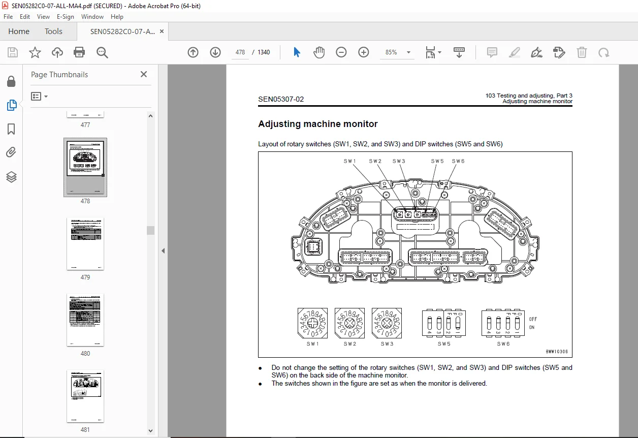
Adjusting machine monitor 478
Adjusting replaced, reassembled or added sensor, controller, etc. withmachine monitor 479
Special functions of machine monitor (EMMS) 481
Pm clinic inspection chart . 0
40 Troubleshooting . 539
100 Failure code table and fuse locations 539
Failure codes table 540
Fuse locations . 546
200 General information on troubleshooting . 551
Points to remember when troubleshooting 552
Sequence of events in troubleshooting 553
Testing before troubleshooting . 554
Classification and procedures of troubleshooting . 555
Information contained in troubleshooting table . 558
Connection table for connector pin numbers . 560
T- branch box and T- branch adapter table 596
301 Troubleshooting by failure code(Display of code), Part 1 . 601
Failure code [2G40ZG] Brake: Oil pressure reduction 602
Failure code [6091NX] HST filter: Clogging . 604
Failure code [989FN1] Travel speed: Overrun alarm 605
Failure code [AB00L6] Alternator R system: Hot short . 606
Failure code [AB00MA] Alternator R system: Ground fault/Disconnection/Low charge voltage . 608
Failure code [B@BAZG] Engine: Oil pressure reduction . 610
Failure code [B@BCNS] Engine: Overheat . 611
Failure code [B@BCZK] Engine: Low coolant level 612
Failure code [B@C6NS] Front brake: High oil temperature 614
Failure code [B@CRNS] HST: High oil temperature 615
302 Troubleshooting by failure code(Display of code), Part 2 . 617
Failure code [CA111] Abnormality in engine controller 619
Failure code [CA115] Engine Ne or Bkup speed sensor error 620
Failure code [CA122] Charge pressure sensor high error . 622
Failure code [CA123] Charge pressure sensor low error 624
Failure code [CA131] Throttle sensor high error 626
Failure code [CA132] Throttle sensor low error . 628
Failure code [CA144] Coolant sensor high error . 630
Failure code [CA145] Coolant sensor low error 632
Failure code [CA153] Charge temperature sensor high error 634
Failure code [CA154] Charge temperature sensor low error . 636
Failure code [CA155] Derating of speed by abnormally high chargetemperature 638
Failure code [CA187] Sensor power supply 2 low error . 640
Failure code [CA221] Atmospheric pressure sensor high error 642
Failure code [CA222] Atmospheric sensor low error 644
Failure code [CA227] Sensor power supply 2 high error 646
code [CA234] Engine overspeed 647
Failure code [CA238] Ne speed sensor power supply error 648
Failure code [CA271] IMV (IMA) Short circuit . 649
Failure code [CA272] IMV (IMA) Disconnection . 650
Failure code [CA322] Injector #1 open/short error 652
Failure code [CA324] Injector #3 open/short error 654
Failure code [CA331] Injector #2 open/short error 656
Failure code [CA332] Injector #4 open/short error 658
Failure code [CA342] Calibration code inconsistency 660
Failure code [CA351] Injectors drive circuit error . 662
Failure code [CA352] Sensor power supply 1 low error . 664
Failure code [CA386] Sensor power supply 1 high error 666
303 Troubleshooting by failure code(Display of code), Part 3 . 669
Failure code [CA428] Abnormally high level in water sensor . 672
Failure code [CA429] Abnormally low level in water sensor 674
Failure code [CA431] Idle validation switch error 676
Failure code [CA432] Idle validation action error 680
Failure code [CA435] Engine oil pressure switch error 684
Failure code [CA441] Battery voltage low error . 685
Failure code [CA442] Battery voltage high error 688
Failure code [CA449] Common rail pressure high error 2 . 690
Failure code [CA451] Common rail pressure sensor high error 692
Failure code [CA452] Common rail pressure sensor low error . 694
Failure code [CA488] Derating of torque by abnormally high chargetemperature . 696
Failure code [CA553] Common rail pressure high error 1 . 697
Failure code [CA559] Supply pump pressure very low error . 698
Failure code [CA689] Engine Ne speed sensor error 700
Failure code [CA731] Engine Bkup speed sensor phase error 702
Failure code [CA757] All continuous data lost error 703
Failure code [CA778] Engine Bkup speed sensor error 706
Failure code [CA1633] KOMNET datalink timeout error 708
Failure code [CA2185] Throttle sensor supply voltage high error 710
Failure code [CA2186] Throttle sensor power supply low error . 712
Failure code [CA2249] Supply pump pressure very low error 2 714
Failure code [CA2311] Abnormality in IMV (IMA) solenoid 716
Failure code [CA2555] Intake heater relay disconnection error 718
Failure code [CA2556] Intake heater relay short circuit error 720
304 Troubleshooting by failure code(Display of code), Part 4 . 723
Failure code [D160KY] Backup alarm/lamp relay 1 circuit: Hot short . 724
Failure code [D192KY] ECSS solenoid relay: Hot short . 726
Failure code [D1B0KA] HST safety relay: Disconnection 728
Failure code [D1B0KB] HST safety relay: Ground fault . 730
Failure code [D1B0KY] HST safety relay: Hot short 732
Failure code [D5ZHL6] IGN C system: Ground fault/Disconnection . 734
Failure code [DAF3KK] UNSW power supply: Ground fault/Disconnection 736
Failure code [DAFRKR] Machine monitor CAN-NET Signal: Disconnection 738
Failure code [DAJ0KK] HST controller power supply: Low voltage . 740
Failure code [DAJ0KT] HST controller memory (EEPROM): Abnormality 742
Failure code [DAJ1L4] HST controller main power line: Disconnection/Ground fault . 744
Failure code [DAJ1L6] HST controller main power line: Hot short 746
Failure code [DAJ2KK] Controller solenoid power supply: Low voltage 748
Failure code [DAJ2L3] HST controller load power supply holding line:Hot short in wiring harness 750
Failure code [DAJ2L4] HST controller load power supply holding line:Disconnection/Ground fault . 752
Failure code [DAJ5KX] Sensor 5V power supply: Out of output range 754
Failure code [DAJ9KQ] HST controller model selection: Disagreementof model selection signals . 756
Failure code [DAJRKR] HST controller CAN-NET signal: Disconnection . 758
Failure code [DAJRMA] HST controller: Disagreement in optionselection 763
305 Troubleshooting by failure code(Display of code), Part 5 . 765
Failure code [DB2RKR] Engine controller CAN-NET: Disconnection insignal line . 766
Failure code [DD1NL4] Fan automatic reverse switch signal: Abnormality1 772
Failure code [DD1NLD] Fan reverse switch signal: Abnormality . 774
Failure code [DDB6KA] Parking brake reminder signal: Disconnection/Hot short . 776
Failure code [DDB6KB] Parking brake indicator signal: Ground fault . 778
Failure code [DDB6KZ] Parking brake switch (bottom switch) or parkingbrake reminder switch (intermediate switch): Trouble 780
Failure code [DDB6L0] Parking brake reminder signal: Ground fault 782
Failure code [DDB6L4] Parking brake indicator signal: Disconnection/Hot short 784
Failure code [DDD7KX] Travel speed control dial signal: Disconnection/Ground fault . 786
Failure code [DDD7KY] Travel speed control dial signal: Hot short 788
Failure code [DDE5MA] Emergency steering operation switch:Disconnection 790
Failure code [DDK6KA] FNR lever: Disconnection/Ground fault 792
Failure code [DDK6KY] FNR lever: Hot short . 796
Failure code [DDS5L6] Steering: Low oil pressure (Operation ofemergency steering) 798
306 Troubleshooting by failure code(Display of code), Part 6 . 801
Failure code [DF10KA] Travel speed range selector switch:Disconnection/Ground fault 802
Failure code [DF10KB] Travel speed range selector switch: Hot sh . 806
Failure code [DGH1KX] HST oil temperature sensor: Ground fault . 808
Failure code [DGR2KB] Brake oil temperature sensor: Ground fault . 809
Failure code [DGR2KZ] Brake oil temperature sensor: Disconnection/Hot short 810
Failure code [DHH1KX] HST oil pressure sensor: Disconnection/Groundfault . 812
Failure code [DHH1KY] HST oil pressure sensor: Hot short . 814
Failure code [DHTCL6] HST filter clogging sensor: Functional defect 816
Failure code [DJF1KA] Fuel level sensor: Disconnection/Hot short . 818
Failure code [DLT3KX] Travel speed sensor B: Abnormality . 820
Failure code [DLT4KX] Travel speed sensor A: Abnormality . 824
Failure code [DV00KY] Alarm buzzer: Hot short 828
Failure code [DW26KA] Motor 2 solenoid: Disconnection/Ground fault . 830
Failure code [DW26KY] Motor 2 solenoid: Hot short 832
Failure code [DW7BKY] Fan reverse solenoid circuit: Hot short 834
Failure code [DW7BKZ] Fan reverse solenoid circuit: Disconnection/Ground fault . 836
Failure code [DLT4LC] Travel speed sensor A & B: Abnormality . 826
307 Troubleshooting by failure code(Display of code), Part 7 . 839
Failure code [DX16KA] Fan EPC solenoid: Disconnection 840
Failure code [DX16KB] Fan EPC solenoid: Ground fault . 841
Failure code [DX16KY] Fan EPC solenoid: Hot short 842
Failure code [DX19KA] Motor 1 solenoid: Disconnection 844
Failure code [DX19KB] Motor 1 solenoid: Ground fault . 846
Failure code [DX19KY] Motor 1 solenoid: Hot short 848
Failure code [DX20KA] Clutch EPC solenoid: Disconnection . 850
Failure code [DX20KB] Clutch EPC solenoid: Ground fault 852
Failure code [DX20KY] Clutch EPC solenoid: Hot short . 854
Failure code [DXH7KB] Reverse solenoid: Ground fault . 856
Failure code [DXH7KZ] Reverse solenoid: Disconnection/Hot short 858
Failure code [DXH8KB] Forward solenoid: Ground fault . 860
Failure code [DXH8KZ] Forward solenoid: Disconnection/Hot short 862
Failure code [J141N1] Steering pump: Overrun alarm . 864
Failure code [M100N1] HST pump: Overrun alarm 865
Failure code [M400N1] Motor 1: Overrun alarm . 866
400 Troubleshooting of electrical system(E-mode) . 869
E-1 Engine does not start 871
E-2 Preheater does not operate normally 878
E-3 Travel speed is low or high 882
E-4 ECSS does not operate 888
E-5 ECSS keeps operating . 891
E-6 Defective boom kick-out function and cancellation 894
E-7 Defective bucket positioner function and cancellation 898
E-8 Defective lift arm FLOATING holding function and cancellation 902
E-9 Travel direction selection system does not function 906
E-10 Fan does not reverse 910
E-11 Fan keeps rotating in reverse . 914
E-12 Wiper does not operate 916
E-13 Windshield washer does not operate 920
E-14 Headlamp, clearance lamp and tail lamp do not light up or go off 924
E-15 Working lamp does not light up or go off 932
E-16 Turn signal lamp and hazard lamp do not light up or go off 937
E-17 Brake lamp does not light or it keeps lighting up . 944
E-18 Backup lamp does not light or it keeps lighting up 946
E-19 Backup alarm does not sound or it keeps sounding 949
E-20 Horn does not sound or it keeps sounding 952
E-21 Alarm buzzer does not sound or it keeps sounding 954
E-22 Air conditioner does not operate or stop 957
E-23 The KOMTRAX system does not work properly . 960
E-24 Rearview monitor does not light up or backlight flickers 962
E-25 Rearview monitor images are not displayed clearly . 966
E-26 Rearview monitor brightness cannot be adjusted 970
E-27 Night lighting lamp of rearview monitor is abnormal . 974
E-28 Reverse interlock function of rearview monitor does not operateproperly . 977
500 Troubleshooting of hydraulic andmechanical system (H-mode) . 981
Method of using troubleshooting chart 983
Failure code and cause table . 986
H-1 The machine does not start . 988
H-2 The travel speed is slow . 989
H-3 The traction force is weak . 990
H-4 Engine stalls when traveling or engine speed drops excessively . 991
H-5 Speed range is not shifted . 992
H-6 The steering wheel does not turn . 993
H-7 The steering wheel is heavy 994
H-8 Steering wheel shakes or jerks . 995
H-9 Machine deviates naturally to one side when traveling 995
H-10 The brake does not work or does not work well . 996
H-11 The brake is not released or is dragged . 997
H-12 The lift arm does not rise or lower . 998
H-13 The lift arm moves slowly or the lift arm rising force is insufficient1 . 999
H-14 When rising, the lift arm comes to move slowly at specific height .1000
H-15 The lift arm cylinder cannot hold down the bucket (The bucketrises in the air) 1000
H-16 Hydraulic drifts of the lift arm occur often 1000
H-17 The lift arm wobbles during operation .1000
H-18 When the control lever is switched from “HOLD” to “RAISE,” thelift arm falls temporarily 1001
H-19 The bucket does not tilt back .1002
H-20 The bucket moves slowly or the tilting-back force is insufficient .1003
H-21 The bucket comes to operate slowly in the midst of tilting-back .1004
H-22 The bucket cylinder cannot hold down the bucket .1004
H-23 Hydraulic drifts of the bucket occur often 1004
H-24 The bucket wobbles during travel with load(The work equipment valve is set to “HOLD”) .1004
H-25 When the control lever is switched from “HOLD” to “TILT,” thebucket falls temporarily .1005
H-26 The control levers of the lift arm and bucket do not move smoothlyand heavy .1005
H-27 The ECSS does not operate and machine pitches and bounces .1006
H-28 Fan revolution is abnormal (Fan sound/vibration is abnormallylarge or engine overheats) .1007
600 Troubleshooting of engine (S-mode) .1009
Method of using troubleshooting charts .1010
S-1 Starting performance is poor .1014
S-2 Engine does not start 1015
S-3 Engine does not pick up smoothly .1018
S-4 Engine stops during operations .1019
S-5 Engine does not rotate smoothly 1020
S-6 Engine lacks output (or lacks power) .1021
S-7 Exhaust smoke is black (incomplete combustion) .1022
S-8 Oil consumption is excessive (or exhaust smoke is blue) 1023
S-9 Oil becomes contaminated quickly .1024
S-10 Fuel consumption is excessive .1025
S-11 Oil is in coolant (or coolant spurts back or coolant level goes down)1 1026
S-12 Oil pressure drops 1027
S-13 Oil level rises (Entry of coolant or fuel) 1028
S-14 Coolant temperature becomes too high (overheating) 1029
S-15 Abnormal noise is made 1030
S-16 Vibration is excessive 1031
50 Disassembly and assembly 1033
100 General information on disassemblyand assembly .1033
How to read this manual 1034
Coating materials list .1036
Special tool list 1039
Sketches of special tools 1043
200 Engine and cooling system 1053
Removal and installation of fuelsupply pump assembly .1054
Removal and installation of fuelinjector assembly 1058
Removal and installation ofcylinder head assembly 1066
Removal and installation ofengine hood assembly 1079
Removal and installation ofradiator 1083
Removal and installation of airaftercooler .1086
Removal and installation ofhydraulic oil cooler assembly .1088
Removal and installation ofengine assembly .1090
Removal and installation ofengine front oil seal assembly 1097
Removal and installation ofengine rear oil seal assembly .1100
Removal and installation ofcooling fan and fan motorassembly .1103
Removal and installation of fueltank assembly 1106
301 Power train, Part 1 1109
Disassembly and assembly oftransfer assembly .1110
Removal and installation ofparking brake assembly 1130
Disassembly and assembly ofparking brake assembly 1132
302 Power train, Part 2 1139
Removal and installation of rearaxle assembly 1142
Disassembly and assembly ofaxle housing assembly .1145
Removal and installation of frontaxle assembly .1140
Disassembly and assembly ofdifferential assembly .1153
400 Undercarriage and frame 1181
Removal and installation of centerhinge pin 1182
Removal and installation ofcounterweight assembly 1191
500 Hydraulic system .1195
Removal and installation of HSTpump and 4-gear pump assembly1 1196
Disassembly and assembly ofHST pump assembly .1200
Removal and installation of HSTmotor 1 assembly 1227
Disassembly and assembly ofHST motor assembly 1231
Removal and installation of workequipment control valveassembly 1247
Removal and installation ofhydraulic tank 1249
Disassembly and assembly ofhydraulic cylinder assembly .1251
600 Work equipment .1257
Removal and installation of workequipment assembly .1258
700 Cab and its attachments 1267
Removal and installation ofoperator’s cab and floor frameassembly 1268
Removal and installation ofoperator’s cab glass(Stuck glass) .1273
Removal and installation of airconditioner unit 1281
800 Electrical system 1289
Removal and installation ofmonitor panel .1290
Removal and installation ofengine controller assembly 1292
Removal and installation of HSTcontroller assembly .1294
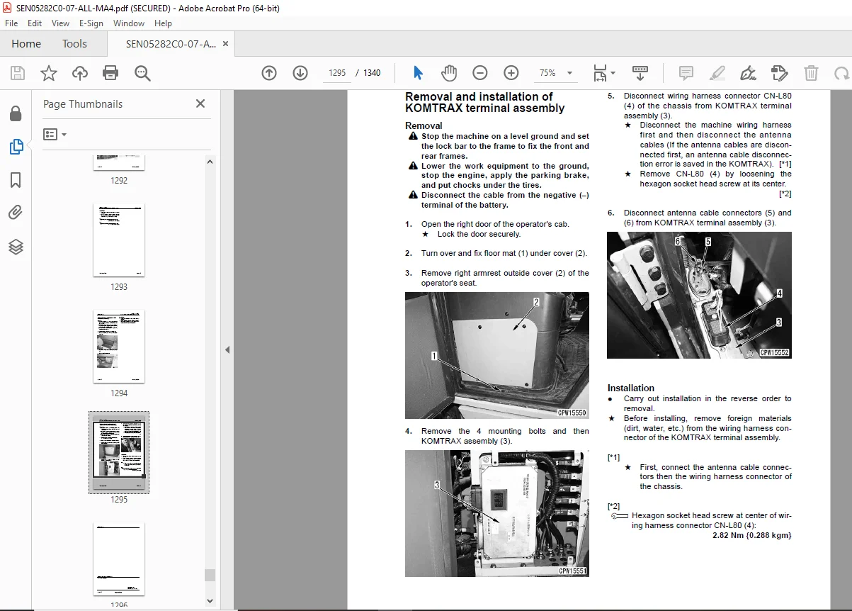
Removal and installation ofKOMTRAX terminal assembly .1295
90 Diagrams and drawings .1297
100 Hydraulic diagrams and drawings 1297
Hydraulic circuit diagram 1299
200 Electrical diagrams and drawings .1305
Common electrical circuit diagram 1322
Specific electrical circuit diagram 1336
Connector list and stereogram 1337
DESCRIPTION:
Komatsu WA200-6,WA200PZ-6 Wheel Loader Shop Manual SEN05282C0-07 – PDF DOWNLOAD
- WA200- C10172 and up
- WA200PZ and up
How to read the shop manual
1. Composition of shop manual
This shop manual contains the necessary technical information for services performed in a workshop.
For ease of understanding, the manual is divided into the following sections.
00. Index and foreword
This section explains the shop manuals list, table of contents, safety, and basic information.
01. Specification
This section explains the specifications of the machine.
10. Structure, function and maintenance standard
This section explains the structure, function, and maintenance standard values of each component.
The structure and function sub-section explains the structure and function of each component. It
serves not only to give an understanding of the structure, but also serves as reference material for
troubleshooting. The maintenance standard sub-section explains the criteria and remedies for disassembly
and service.
20. Standard value table
This section explains the standard values for new machine and judgement criteria for testing,
adjusting, and troubleshooting. This standard value table is used to check the standard values in
testing and adjusting and to judge parts in troubleshooting.
30. Testing and adjusting
This section explains measuring instruments and measuring methods for testing and adjusting, and
method of adjusting each part. The standard values and judgement criteria for testing and adjusting
are explained in Testing and adjusting.
40. Troubleshooting
This section explains how to find out failed parts and how to repair them. The troubleshooting is
divided by failure modes. The “S mode” of the troubleshooting related to the engine may be also
explained in the Chassis volume and Engine volume. In this case, see the Chassis volume.
50. Disassembly and assembly
This section explains the special tools and procedures for removing, installing, disassembling, and
assembling each component, as well as precautions for them. In addition, tightening torque and
quantity and weight of coating material, oil, grease, and coolant necessary for the work are also
explained.
90. Diagrams and drawings (chassis volume)/Repair and replacement of parts (engine volume)
q Chassis volume
This section gives hydraulic circuit diagrams and electrical circuit diagrams.
q Engine volume
This section explains the method of reproducing, repairing, and replacing parts.
G.B 29/12/24


