Komatsu WA200-5 WA200L-5 WA200PT-5 WA200PTL-5 Wheel Loader Shop Manual PDF
$32.95
Komatsu WA200-5 WA200L-5 WA200PT-5 WA200PTL-5 Wheel Loader Shop Manual SEBM033304 – PDF DOWNLOAD
SERIAL NUMBERS
WA200-5 65001 and up
WA200L-5 65001 and up
WA200PT-5 65001 and up
WA200PTL-5 65001 and up
Description
Komatsu WA200-5 WA200L-5 WA200PT-5 WA200PTL-5 Wheel Loader Shop Manual SEBM033304 – PDF DOWNLOAD
FILE DETAILS:
Komatsu WA200-5 WA200L-5 WA200PT-5 WA200PTL-5 Wheel Loader Shop Manual SEBM033304 – PDF DOWNLOAD
Language : English
Pages : 791
Downloadable : Yes
File Type : PDF
IMAGES PREVIEW OF THE MANUAL:
TABLE OF CONTENTS:
Komatsu WA200-5 WA200L-5 WA200PT-5 WA200PTL-5 Wheel Loader Shop Manual SEBM033304 – PDF DOWNLOAD
SERIAL NUMBERS
WA200-5 65001 and up
WA200L-5 65001 and up
WA200PT-5 65001 and up
WA200PTL-5 65001 and up
MAIN MENU 0
COVER 1
CONTENTS 2
SAFETY 8
SAFETY NOTICE 8
FOREWORD 10
GENERAL 10
HOW TO READ THE SHOP MANUAL 11
HOISTING INSTRUCTIONS 12
METHOD OF DISASSEMBLING, CONNECTING PUSH-PULL TYPE COUPLER 13
COATING MATERIALS 15
STANDARD TIGHTENING TORQUE 17
ELECTRIC WIRE CODE 20
CONVERSION TABLE 21
UNITS 27
01 GENERAL 28
GENERAL ASSEMBLY DRAWINGS 29
SPECIFICATIONS 30
WEIGHT TABLE 34
LIST OF LUBRICANT AND COOLANT 36
10 STRUCTURE, FUNCTION AND MAINTENANCE STANDARD 37
ENGINE MOUNT AND TRANSFER MOUNT 38
DAMPER 39
COOLING SYSTEM 40
TRANSFER OIL COOLER 41
POWER TRAIN 42
POWER TRAIN SYSTEM DIAGRAM 44
DRIVE SHAFT (PROPELLER SHAFT) 46
HST HYDRAULIC PIPING DIAGRAM 47
HST PUMP 48
HIGH-PRESSURE RELIEF VALVE 50
LOW-PRESSURE RELIEF VALVE 52
HST CHARGE PUMP 53
SPEED-RELATED VALVE (DA VALVE) 54
HIGH-PRESSURE CUT-OFF VALVE 55
HST MOTOR 56
EP SERVO VALVE 59
HA SERVO VALVE 60
FORWARD-REVERSE SHUTTLE VALVE 61
TRANSFER 62
CLUTCH SOLENOID VALVE 73
AXLE 74
DIFFERENTIAL 76
LIMITED-SLIP DIFFERENTIAL 82
FINAL DRIVE 86
AXLE MOUNTING AND CENTER HINGE PIN 88
STEERING PIPING 93
STEERING COLUMN 94
PRIORITY VALVE 95
ORBIT-ROLL VALVE 98
2-WAY RESTRICTOR VALVE 106
CUSHION VALVE 107
STEERING CYLINDER 108
EMERGENCY STEERING PIPING 110
EMERGENCY STEERING VALVE 111
BRAKE PIPING 114
BRAKE VALVE 115
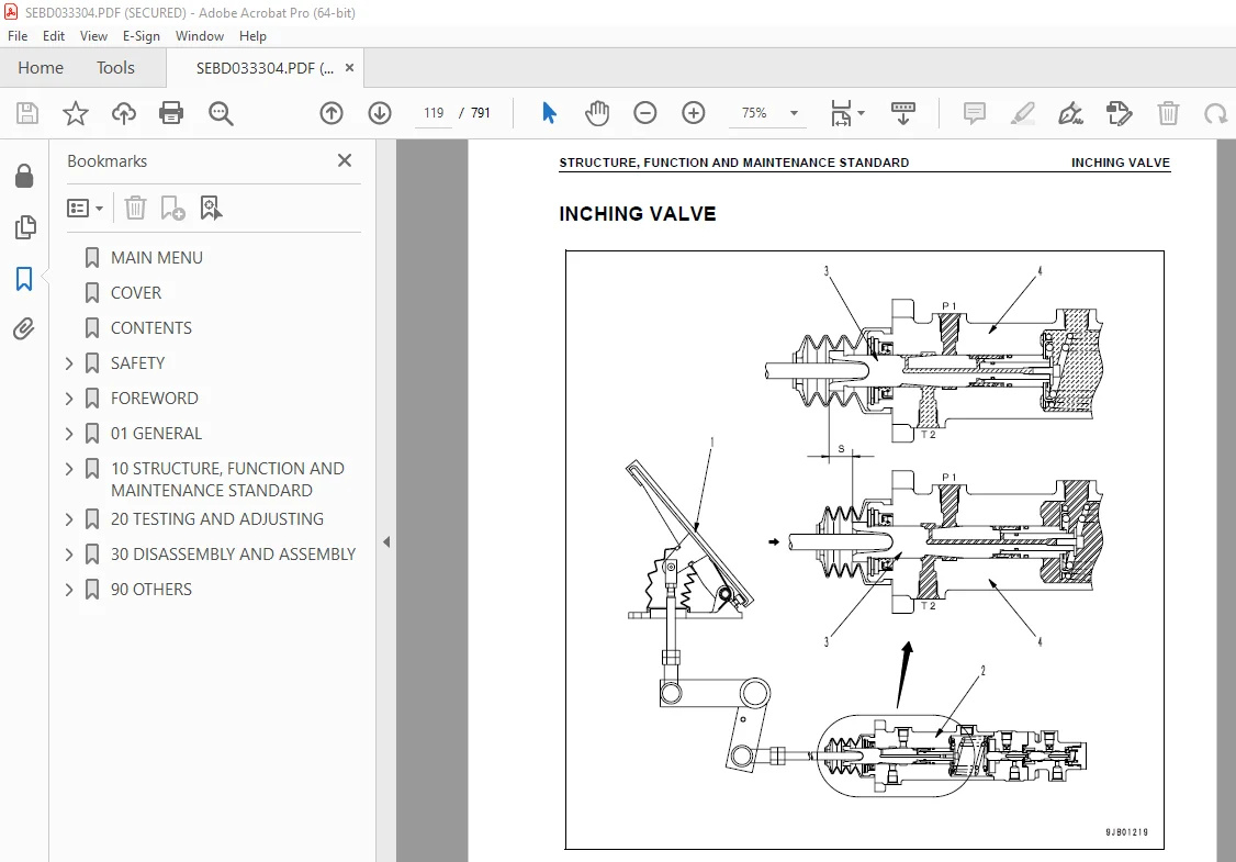
INCHING VALVE 119
CHARGE VALVE 120
ACCUMULATOR (FOR BRAKE) 124
SLACK ADJUSTER 125
BRAKE 128
PARKING BRAKE CONTROL 131
PARKING BRAKE 132
HYDRAULIC PIPING 134
WORK EQUIPMENT LEVER LINKAGE 138
HYDRAULIC TANK 142
4-GEAR PUMP UNIT 145
ACCUMULATOR (FOR PPC CIRCUIT) 147
LOCK VALVE 148
BYPASS VALVE 149
QUICK COUPLER VALVE 152
E C S S VALVE 153
ACCUMULATOR (FOR E C S S ) 155
HYDRAULIC PIPING OF COOLING SYSTEM 156
COOLING FAN MOTOR 157
WORK EQUIPMENT CONTROL VALVE 159
WORK EQUIPMENT PPC VALVE 172
ATTACHMENT PPC VALVE 181
WORK EQUIPMENT LINKAGE 185
BUCKET 189
CONTROL OF BUCKET POSITIONER, BOOM KICK-OUT, AND DUMP SPEED 191
WORK EQUIPMENT CYLINDER 205
AIR CONDITIONER 208
MACHINE MONITORING SYSTEM 210
MACHINE MONITOR 219
LIST OF ITEMS DISPLAYED ON MONITOR 220
ELECTRICAL SYSTEM (HST CONTROLLER SYSTEM) 246
HST CONTROLLER 250
ENGINE START CIRCUIT 251
ENGINE STOP CIRCUIT 253
PREHEATING CIRCUIT (AUTOMATIC PREHEATING SYSTEM) 254
PARKING BRAKE CIRCUIT 255
ELECTRONICALLY CONTROLLED SUSPENSION SYSTEM 258
SENSORS 259
20 TESTING AND ADJUSTING 265
STANDARD VALUE TABLE FOR ENGINE 266
STANDARD VALUE TABLE FOR CHASSIS 267
TESTING AND ADJUSTING 271
TOOLS FOR TESTING, ADJUSTING, AND TROUBLESHOOTING 272
MEASURING ENGINE SPEED 274
MEASURING EXHAUST GAS COLOR 276
ADJUSTING VALVE CLEARANCE 277
MEASURING COMPRESSION PRESSURE 279
MEASURING BLOW-BY PRESSURE 280
TESTING AND ADJUSTING FUEL INJECTION TIMING 281
MEASURING ENGINE OIL PRESSURE 282
MEASURING, TESTING OPERATING FORCE OF ACCELERATOR PEDAL 283
ADJUSTING ENGINE STOP SOLENOID 285
ADJUSTING ENGINE SPEED SENSOR 286
TESTING AND ADJUSTING AIR CONDITIONER COMPRESSOR BELT TENSION 286
MEASURING DIRECTIONAL LEVER 287
TESTING AND ADJUSTING HST OIL PRESSURE 288
MEASURING CLUTCH CONTROL PRESSURE 293
TESTING AND ADJUSTING STEERING WHEEL 294
TESTING AND ADJUSTING STEERING OIL PRESSURE 296
BLEEDING AIR FROM STEERING CIRCUIT 298
TESTING HYDRAULIC FAN 299
MEASURING BRAKE PEDAL 300
TESTING AND ADJUSTING BRAKE PEDAL LINKAGE 301
MEASURING BRAKE PERFORMANCE 302
TESTING AND ADJUSTING ACCUMULATOR CHARGE PRESSURE 0
MEASURING BRAKE OIL PRESSURE 303
MEASURING WEAR OF BRAKE DISC 306
BLEEDING AIR FROM BRAKE CIRCUIT 307
MEASURING PARKING BRAKE PERFORMANCE 308
TESTING AND ADJUSTING PARKING BRAKE CONTROL CABLE 309
MEASURING AND ADJUSTING WORK EQUIPMENT CONTROL LEVER 310
TESTING AND ADJUSTING WORK EQUIPMENT HYDRAULIC PRESSURE 311
TESTING AND ADJUSTING WORK EQUIPMENT PPC OIL PRESSURE 312
BLEEDING AIR 314
RELEASING REMAINING PRESSURE IN HYDRAULIC CIRCUIT 315
TESTING AND ADJUSTING BUCKET POSITIONER 316
TESTING AND ADJUSTING OF BOOM KICK-OUT 317
CHECKING PROXIMITY SWITCH ACTUATION DISPLAY LAMP 318
PROCEDURE FOR CHECKING DIODE 319
METHOD OF CONNECTING T-ADAPTER FOR HST CONTROLLER 320
SPECIAL FUNCTIONS OF MACHINE MONITOR 321
FLOW OF MODES AND FUNCTIONS 322
PM CLINIC INSPECTION CHART 340
TROUBLESHOOTING 343
POINTS TO REMEMBER WHEN TROUBLESHOOTING 344
SEQUENCE OF EVENTS IN TROUBLESHOOTING 345
PRECAUTIONS WHEN CARRYING OUT MAINTENANCE 346
CHECK BEFORE TROUBLESHOOTING 354
CATEGORIES, PROCEDURE, AND METHOD OF USING TROUBLESHOOTING CHARTS 355
PHENOMENA CONSIDERED TO BE FAILURES AND TROUBLESHOOTING NO 356
CONNECTION TABLE FOR CONNECTOR PIN NUMBERS 360
T-ADAPTER TABLE 382
CONNECTOR TYPES AND MOUNTING LOCATIONS 385
CONNECTOR LAYOUT DRAWING 392
TROUBLESHOOTING OF HST CONTROLLER SYSTEM (HST MODE) 397
HST CONTROLLER SYSTEM DIAGRAM 398
BEFORE TROUBLESHOOTING CODE DISPLAY 400
BEFORE TROUBLESHOOTING ELECTRICAL SYSTEM 401
INFORMATION CONTAINED IN TROUBLESHOOTING TABLE 402
Error Code [989F00] (HST motor protection caution (00)) 404
Error Code [DDD7KX] (Speedmeter system input signal is out of range (KX)) 405
Error Code [DHH1KX] (HST oil pressure sensor input signal outside range (KX)) 407
Error Code [DLE2LC] (Engine revolution sensor revolution speed signal mismatch (LC)) 409
Error Code [DLT3KA] (Speedmeter system discontinuity (KA)) 410
Error Code [DW26KZ] (Motor 2 solenoid system discontinuity or short-circuiting (KZ)) 412
Error Code [DX19KZ] (Motor 1 solenoid system discontinuity or short-circuiting (KZ)) 414
Error Code [DX20KZ] (Clutch solenoid system discontinuity or short circuiting (KZ)) 416
Troubleshooting Code [HST-1] (Defective HST controller power source (HST controller does not function)) 418
Troubleshooting Code [HST-2] (Travel speed does not shifted) 420
Troubleshooting Code [HST-3] HST Output Control (Traction control) cannot be controlled 423
TROUBLESHOOTING OF TRAVEL DAMPER SYSTEM (ECSS MODE) 425
RELATED ELECTRICAL CIRCUIT DIAGRAM 426
ECSS-1 MALFUNCTION OF TRAVEL DAMPER 427
TROUBLESHOOTING OF MONITOR SYSTEM (MON MODE) 432
MONITOR SYSTEM CIRCUIT DIAGRAM 433
BEFORE TROUBLESHOOTING CODE DISPLAY 437
BEFORE TROUBLESHOOTING ELECTRICAL SYSTEM 438
INFORMATION CONTAINED IN TROUBLESHOOTING TABLE 439
Error Code [15B0NX] (HST oil filter clogged (NX)) 441
Error Code [2G42ZG] (Decreased brake oil pressure (ZG)) 442
Error Code [989F00] (HST motor protection caution (00)) 443
Error Code [989FN1] (HST overrunning (N1)) 444
Error Code [AB00L6] (Defective battery charging circuit (L6)) 445
Error Code [AB00MA] (Defective battery charging circuit (MA)) 446
Error Code [B@BAZG] (Degreased engine oil pressure (ZG)) 447
Error Code [B@BCNS] (Engine water temperature overheating (NS)) 448
Error Code [B@BCZK] (Alarm indicating low coolant level (ZK)) 449
Error Code [B@C7NS] (Axle oil temperature overheating (NS)) 450
Error Code [B@CRNS] (HST oil temperature overheating (NS)) 451
Error Code [D5ZHL6] (Starting switch “C” (IGN “C”) input failure (LS)) 453
Error Code [DAF0KT] (Controller inside failure (KT)) 455
Error Code [DAJ0KR] (HST controller communication failure (KR)) 457
Error Code [DD15LD] (Monitor panel mode selector switch 1 [ ] (Panel switch 1) input error (LD)) 459
Error Code [DD16LD] (Monitor panel mode selector switch 1 [ ] (Panel switch 2) input error (LD)) 460
Error Code [DD17LD] (Monitor panel mode selector switch 2 [<] (Panel switch 3) input error (LD)) 461
Error Code [DD18LD] (Monitor panel mode selector switch 2 [>] (Panel switch 4) input error (LD)) 462
Error Code [DDK3KB] (Multiple directional lever FR signal input (KB)) 463
Error Code [DDS5L6] (Decreased steering oil pressure (L6)) 465
Error Code [DGE2KX] (Engine water temperature (High temperature) sensor system failure (KX)) 466
Error Code [DGE3L6] (Engine water temperature (Low temperature) sensor system failure (L6)) 467
Error Code [DGH1KX] (HST oil temperature sensor system failure (KX)) 468
Error Code [DGR4KA] (Axle oil temperature sensor system discontinuity (KA)) 469
Error Code [DGR4KX] (Axle oil temperature sensor system failure (KX)) 470
Error Code [DHE4L6] (Engine oil pressure sensor system discontinuity (L6)) 471
Troubleshooting Code [MON-1] (The parking brake indicator lamp does not light ON) 473
Troubleshooting Code [MON-2] (The brake oil pressure caution lamp does not light ON) 477
Troubleshooting Code [MON-3] (The engine water temperature caution lamp does not light ON, or after the engine starts, the engine water temperature gauge does not rise ) 478
Troubleshooting Code [MON-4] (The HST oil temperature caution lamp does not light ON, or after the engine starts, the HST oil temperature gauge does not rise ) 479
Troubleshooting Code [MON-5] (The fuel level gauge does not rise or decrease ) 480
Troubleshooting Code [MON-6] (The radiator coolant level caution lamp does not light ON) 481
Troubleshooting Code [MON-7] (The steering oil pressure caution lamp does not light ON) 482
Troubleshooting Code [MON-8] (The emergency steering oil pressure indicator lamp does not light ON) 483
Troubleshooting Code [MON-9] (Input failure in monitor panel mode selector switch 1 [ ] (Panel switch 1) 484
Troubleshooting Code [MON-10] (Input failure in monitor panel mode selector switch 1 [ ] (Panel switch 2)) 485
Troubleshooting Code [MON-11] (Input failure in monitor panel mode selector switch 2 [<] (Panel switch 3)) 486
Troubleshooting Code [MON-12] (Input failure in monitor panel mode selector switch 2 [>] (Panel switch 4)) 487
Troubleshooting Code [MON-13] (The alarm buzzer does not sound or stop) 488
Troubleshooting Code [MON-14] The wiper does not function 489
Troubleshooting Code [MON-15] The lamps do not work properly 489
TROUBLESHOOTING OF ELECTRICAL SYSTEM (E MODE) 490
ELECTRICAL SYSTEM DIAGRAM 491
PARKING BRAKE RELATED DIAGRAM 495
BEFORE TROUBLESHOOTING ELECTRICAL SYSTEM 497
INFORMATION CONTAINED IN TROUBLESHOOTING TABLE 499
Troubleshooting Code [E-1] (The engine does not start) 501
Troubleshooting Code [E-2] (The engine does not stop) 507
Troubleshooting Code [E-3] (Preheating is impossible or constant) 509
Troubleshooting Code [E-4] (The parking brake (Mechanical type) does not function) 513
Troubleshooting Code [E-5] (Defective boom kick-out function and cancellation) 520
Troubleshooting Code [E-6] (Defective bucket positioner function and cancellation) 523
Troubleshooting Code [E-7] (Defective lift arm FLOATING holding function and cancellation) 526
Troubleshooting Code [E-8] (Travel direction is not changed normally) 527
Troubleshooting Code [E-9] (The wiper does not function) 532
Troubleshooting Code [E-10] (The window washer does not function) 537
Troubleshooting Code [E-11] (Lamps do not work properly) 540
Troubleshooting Code [E-12] (The horn does not sound) 551
Troubleshooting Code [E-13] (Defective the air conditioner) 553
TROUBLESHOOTING OF HYDRAULIC, MECHANICAL SYSTEM (H MODE) 561
METHOD OF USING TROUBLESHOOTING CHART 562
FAILURE CODE AND CAUSE TABLE 564
H-1 The machine does not start 566
H-2 The travel speed is slow 567
H-3 The thrusting force is weak 568
H-4 Engine stalls when traveling or engine speed drops excessively 569
H-5 The gear is not shifted 570
H-6 The steering wheel does not turn 571
H-7 The steering wheel is heavy 572
H-8 Steering wheel shakes or jerks 573
H-9 Machine deviates naturally to one side when traveling 573
H-10 The brake does not work or does not work well 574
H-11 The brake is not released or is dragged 575
H-12 The lift arm does not rise or lower 577
H-13 The lift arm moves slowly or the lift arm rising force is insufficient 578
H-14 When rising, the lift arm comes to move slowly at specific height 579
H-15 The lift arm cylinder cannot hold down the bucket (The bucket rises in the air) 579
H-16 Hydraulic drifts of the lift arm occur often 579
H-17 The lift arm wobbles during operation 579
H-18 When the control lever is switched from “HOLD” to “RAISE,” the lift arm falls temporarily 580
H-19 The bucket does not tilt back 581
H-20 The bucket moves slowly or the tilting-back force is insufficient 582
H-21 The bucket comes to operate slowly in he midst of tilting-back 583
H-22 The bucket cylinder cannot hold down the bucket 583
H-23 Hydraulic drifts of the bucket occur often 583
H-24 The bucket wobbles during travel with cargo (The work equipment valve is set to “HOLD”) 584
H-25 When the control lever is switched from “HOLD” to “TILT,” the bucket falls temporarily 584
H-26 The control levers of the lift arm and bucket do not move smoothly and heavy 584
H-27 The travel damper does not operate and machine pitches and bounces 585
TROUBLESHOOTING OF ENGINE (S MODE) 586
METHOD OF USING TROUBLESHOOTING CHARTS 587
S-1 Starting performance is poor (Starting always takes time) 591
S-2 Engine does not start 593
(1) Engine does not turn 593
(2) Engine turns but no exhaust smoke comes out (Fuel is not being injected) 594
(3) Exhaust smoke comes out but engine does not start (Fuel is being injected) 595
S-3 Engine does not pick up smoothly (Follow-up is poor) 596
S-4 Engine stops during operations 597
S-5 Engine does not rotate smoothly (Hunting) 598
S-6 Engine lacks output (or lacks power) 599
S-7 Exhaust smoke is black (incomplete combustion) 600
S-8 Oil consumption is excessive (or exhaust smoke is blue) 601
S-9 Oil becomes contaminated quickly 602
S-10 Fuel consumption is excessive 603
S-11 Oil is in cooling water, or water spurts back, or water level goes down 604
S-12 Oil pressure caution lamp lights up (Drop in oil pressure) 605
S-13 Oil level rises (Water, fuel in oil) 606
S-14 Water temperature becomes too high (Overheating) 607
S-15 Abnormal noise is made 608
S-16 Vibration is excessive 609
30 DISASSEMBLY AND ASSEMBLY 610
HOW TO READ THIS MANUAL 611
PRECAUTIONS WHEN PERFORMING OPERATION 613
SPECIAL TOOL LIST 615
SKETCHES OF SPECIAL TOOLS 618
REMOVAL AND INSTALLATION OF FUEL INJECTION PUMP ASSEMBLY 625
REMOVAL AND INSTALLATION OF NOZZLE HOLDER ASSEMBLY 630
REMOVAL AND INSTALLATION OF CYLINDER HEAD ASSEMBLY 631
REMOVAL AND INSTALLATION OF ENGINE 639
REMOVAL AND INSTALLATION OF RADIATOR ASSEMBLY 646
REMOVAL AND INSTALLATION OF AIR AFTERCOOLER ASSEMBLY 647
REMOVAL AND INSTALLATION OF HYDRAULIC OIL COOLER ASSEMBLY 649
REMOVAL AND INSTALLATION OF COOLING FAN AND FAN MOTOR ASSEMBLY 651
REMOVAL AND INSTALLATION OF FUEL TANK ASSEMBLY 652
REMOVAL AND INSTALLATION OF TRANSFER ASSEMBLY 654
DISASSEMBLY AND ASSEMBLY OF TRANSFER ASSEMBLY 657
REMOVAL AND INSTALLATION OF PARKING BRAKE ASSEMBLY 676
DISASSEMBLY AND ASSEMBLY OF PARKING BRAKE ASSEMBLY 678
REMOVAL AND INSTALLATION OF FRONT AXLE ASSEMBLY 683
REMOVAL AND INSTALLATION OF REAR AXLE ASSEMBLY 684
DISASSEMBLY AND ASSEMBLY OF AXLE HOUSING ASSEMBLY 687
DISASSEMBLY AND ASSEMBLY OF DIFFERENTIAL ASSEMBLY 695
REMOVAL AND INSTALLATION OF HST PUMP AND 4 GEAR PUMP ASSEMBLY 721
REMOVAL AND INSTALLATION OF HST MOTOR 1 ASSEMBLY 724
REMOVAL AND INSTALLATION OF HST MOTOR 2 ASSEMBLY 725
REMOVAL AND INSTALLATION OF WORK EQUIPMENT CONTROL VALVE ASSEMBLY 727
REMOVAL AND INSTALLATION OF TRAVEL DAMPER VALVE ASSEMBLY 728
REMOVAL AND INSTALLATION OF HYDRAULIC TANK 730
REMOVAL AND INSTALLATION OF WORK EQUIPMENT ASSEMBLY 731
DISASSEMBLY AND ASSEMBLY OF HYDRAULIC CYLINDER ASSEMBLY 738
REMOVAL AND INSTALLATION OF OPERATOR’S CAB ASSEMBLY 746
REMOVAL AND INSTALLATION OF OPERATOR’S CAB GLASS (STUCK GLASS) 751
REMOVAL AND INSTALLATION OF CENTER HINGE PIN 759
REMOVAL AND INSTALLATION OF COUNTERWEIGHT 766
REMOVAL AND INSTALLATION OF AIR CONDITIONER UNIT ASSEMBLY 768
REMOVAL AND INSTALLATION OF AIR CONDITIONER COMPRESSOR ASSEMBLY 771
REMOVAL AND INSTALLATION OF MONITOR PANEL 772
90 OTHERS 775
HYDRAULIC CIRCUIT DIAGRAM WA200-5 776
HYDRAULIC CIRCUIT DIAGRAM WA200PT-5 777
ELECTRICAL CIRCUIT DIAGRAM 1/4 (1/4) (Machines equipped with ROPS cab) 778
ELECTRICAL CIRCUIT DIAGRAM 1/4 (2/4) (Machines equipped with ROPS cab) 779
ELECTRICAL CIRCUIT DIAGRAM 1/4 (3/4) (Machines equipped with ROPS cab) 780
ELECTRICAL CIRCUIT DIAGRAM 1/4 (4/4) (Machines equipped with ROPS cab) 781
ELECTRICAL CIRCUIT DIAGRAM 2/4 (Machines equipped with ROPS cab) 782
ELECTRICAL CIRCUIT DIAGRAM 3/4 (Machines equipped with ROPS cab) 783
ELECTRICAL CIRCUIT DIAGRAM 4/4 (Machines equipped with ROPS cab) 784
ELECTRICAL CIRCUIT DIAGRAM 1/4 (1/4) (Machines equipped with ROPS canopy) 785
ELECTRICAL CIRCUIT DIAGRAM 1/4 (2/4) (Machines equipped with ROPS canopy) 786
ELECTRICAL CIRCUIT DIAGRAM 1/4 (3/4) (Machines equipped with ROPS canopy) 787
ELECTRICAL CIRCUIT DIAGRAM 1/4 (4/4) (Machines equipped with ROPS canopy) 788
ELECTRICAL CIRCUIT DIAGRAM 2/4 (Machines equipped with ROPS canopy) 789
ELECTRICAL CIRCUIT DIAGRAM 3/4 (Machines equipped with ROPS canopy) 790
ELECTRICAL CIRCUIT DIAGRAM 4/4 (Machines equipped with ROPS canopy) 791
DESCRIPTION:
Komatsu WA200-5 WA200L-5 WA200PT-5 WA200PTL-5 Wheel Loader Shop Manual SEBM033304 – PDF DOWNLOAD
SERIAL NUMBERS
WA200-5 65001 and up
WA200L-5 65001 and up
WA200PT-5 65001 and up
WA200PTL-5 65001 and up
FOREWORD
GENERAL
This shop manual has been prepared as an aid to improve the quality of repairs by giving the serviceman an
accurate understanding of the product and by showing him the correct way to perform repairs and make judgements.
Make sure you understand the contents of this manual and use it to full effect at every opportunity.
This shop manual mainly contains the necessary technical information for operations performed in a service
workshop. For ease of understanding, the manual is divided into the following chapters; these chapters are further
divided into the each main group of components.
STRUCTURE AND FUNCTION
This section explains the structure and function of each component. It serves not only to give an understanding
of the structure, but also serves as reference material for troubleshooting.
In addition, this section may contain hydraulic circuit diagrams, electric circuit diagrams, and maintenance
standards.
TESTING AND ADJUSTING
This section explains checks to be made before and after performing repairs, as well as adjustments to
be made at completion of the checks and repairs.
Troubleshooting charts correlating “Problems” with “Causes” are also included in this section.
DISASSEMBLY AND ASSEMBLY
This section explains the procedures for removing, installing, disassembling and assembling each component,
as well as precautions for them.
MAINTENANCE STANDARD
This section gives the judgment standards for inspection of disassembled parts.
The contents of this section may be described in STRUCTURE AND FUNCTION.
OTHERS
This section mainly gives hydraulic circuit diagrams and electric circuit diagrams.
In addition, this section may give the specifications of attachments and options together.
S.V 28/12/24


