Komatsu WA100M-8E0 Wheel Loader Shop Manual VENBM07002 PDF
$37.95
Komatsu WA100M-8E0 Wheel Loader Shop Manual VENBM07002 – PDF DOWNLOAD
Model: Serial number:
WA100M-8E0 H11201 AND UP
Description
Komatsu WA100M-8E0 Wheel Loader Shop Manual VENBM07002 – PDF DOWNLOAD
FILE DETAILS:
Komatsu WA100M-8E0 Wheel Loader Shop Manual VENBM07002 – PDF DOWNLOAD
Language : English
Pages : 1084
Downloadable : Yes
File Type : PDF
IMAGES PREVIEW OF THE MANUAL:
TABLE OF CONTENTS:
Komatsu WA100M-8E0 Wheel Loader Shop Manual VENBM07002 – PDF DOWNLOAD
Model: Serial number:
WA100M-8E0 H11201 AND UP
VENBM07002 WA100M-8E0 1
INDEX AND FOREWORD 3
ABBREVIATION LIST 4
List of abbreviations used in the text 4
List of abbreviations used in the circuit diagrams 9
FOREWORD, SAFETY, BASIC INFORMATION 10
HOW TO READ THE SHOP MANUAL 10
Composition of the shop manual 10
Symbols 12
Signal word 12
Unit 12
SAFETY NOTICE FOR OPERATION 13
Safety matters 13
General precautions 14
Precautions for preparatory work 15
Precautions during work 15
Precautions for slinging work and making signals 17
Precautions for using mobile crane 20
Precautions for using overhead traveling crane 20
Selecting wire ropes 21
PRECAUTIONS TO PREVENT FIRE 23
Fire caused by fuel, oil, coolant or window washer fluid 23
Fire caused by accumulation or attachment of flammable material 23
Fire coming from electric wiring 23
Fire caused by piping 24
Fire around the machine due to highly heated exhaust gas 24
Explosion caused by lighting equipment 24
ACTIONS IF FIRE OCCURS 25
PRECAUTIONS FOR DISPOSING OF WASTE MATERIALS 26
ACTIONS TAKEN TO MEET EXHAUST GAS REGULATIONS 27
About DEF 27
PRECAUTIONS FOR DEF 28
General character and precautions for handling 28
Precautions for adding 28
Precautions for storing 28
Precautions for fire hazard and leakage 28
The other precautions 29
STORE AdBlue/DEF 30
Handling AdBlue/DEF in cold weather 30
PRECAUTIONS FOR HANDLING HYDRAULIC EQUIPMENT 31
Select an appropriate workplace 31
Disassembly and maintenance work in the field 31
Sealing of openings (prevention of flowing out of oil) 31
Preventing intrusion of foreign materials during refilling 32
Replacing hydraulic oil while its temperature is high 32
Avoid reusing the hydraulic oil and lubricating oil 32
Flushing operation 33
Cleaning operation 33
PRECAUTIONS FOR DISCONNECTION AND CONNECTION OF PIPINGS 34
PRECAUTIONS FOR HANDLING ELECTRICAL EQUIPMENT 45
Defective contact of connectors (defective contact between male and female connectors) 45
Defective crimping or soldering of connectors 46
Disconnection in wiring 46
Water entering the connector by high-pressure jetting 46
Entry of water, dirt, or dust when disconnecting a connector 46
Oil, mud, or dust stuck to connector 47
Select an appropriate workplace 48
Sealing the opening 48
How to clean parts when dirt is stuck 48
Precautions for replacing fuel filter cartridge 48
Select an appropriate workplace 49
Sealing the opening 49
PRACTICAL USE OF KOMTRAX 50
Merit of using KOMTRAX 50
How to make a full use of KOMTRAX 51
How to operate KOMTRAX 51
Disconnecting connectors 52
Connecting connectors 53
Drying wiring harness 55
Handling controller 56
Method for disconnecting Deutsch connector 57
Method for connecting Deutsch connector 57
Method for disconnecting slide lock type connector (FRAMATOME-3, FRAMATOME-2) 58
Method for connecting slide lock type connector (FRAMATOME-3, FRAMATOME-2) 58
Method for disconnecting slide lock type connector (FRAMATOME-24) 58
Method for connecting slide lock type connector (FRAMATOME-24) 58
Method for disconnecting connector with lock to pull 59
Method for connecting connector with lock to pull 59
Method for disconnecting connector with lock to push (BOSCH-3) 60
Method for connecting connector with lock to push (BOSCH-3) 60
Method for disconnecting connector with lock to push (AMP-3) 61
Method for connecting connector with lock to push (AMP-3) 61
Method for disconnecting connector with lock to push (SUMITOMO-3) 61
Method for connecting connector with lock to push (SUMITOMO-3) 61
Method for disconnecting connector with lock to push (SUMITOMO-4) 61
Method for connecting connector with lock to push (SUMITOMO-4) 61
Method for disconnecting connector with housing to rotate 62
Method for connecting connector with housing to rotate 62
Method for connecting ring terminals and strip fuses to power stud of printed circuit boards 63
HOW TO READ ELECTRICAL WIRE CODE 64
TYPE, SYMBOL, AND MATERIAL 64
COLOR CODES TABLE 65
EXPLANATION OF TERMS FOR MAINTENANCE STANDARD 66
STANDARD DIMENSION AND TOLERANCE 66
STANDARD CLEARANCE AND STANDARD VALUE 67
STANDARD INTERFERENCE 67
REPAIR LIMIT AND ALLOWABLE VALUE OR ALLOWABLE DIMENSION 67
ALLOWABLE CLEARANCE 68
ALLOWABLE INTERFERENCE 68
STANDARD TIGHTENING TORQUE TABLE 69
CONVERSION TABLE 77
METHOD OF USING THE CONVERSION TABLE 77
EXAMPLES OF USING THE CONVERSION TABLE TO CONVERT A UNIT FROM MM TO IN 77
TEMPERATURE 81
SPECIFICATIONS 83
DIMENSIONS, WEIGHTS AND OPERATING DATA 84
SPECIFICATIONS 86
WEIGHT TABLES 87
LUBRICANTS AND OPERATING MEDIUMS 88
BASIC PROCEDURES OF MAINTENANCE 90
OIL 90
FUEL 90
COOLANT 91
GREASE 91
STORING OIL AND FUEL 91
FILTERS 92
OUTLINE OF ELECTRIC SYSTEM 92
TIGHTENING TORQUE LIST – METRIC SCREWS AND NUTS 93
STRUCTURE AND FUNCTION 95
ABBREVIATION LIST 99
List of abbreviations used in the text 99
List of abbreviations used in the circuit diagrams 104
UREA SCR SYSTEM 105
UREA SCR SYSTEM DIAGRAM 107
FUNCTION OF UREA SCR SYSTEM 108
FUNCTION OF AdBlue/DEF SYSTEM 109
AdBlue/DEF INJECTION FUNCTION 109
AdBlue/DEF PURGE FUNCTION 110
FUNCTION OF AdBlue/DEF THAWING AND PREVENTING FROM FREEZING 110
INDUCEMENT STRATEGY 111
INDUCEMENT STRATEGY WHEN THE AdBlue/DEF LEVEL IN THE TANK BECOMES LOW 111
INDUCEMENT STRATEGY WHEN ABNORMALITY IS FOUND IN THE AdBlue/DEF QUALITY OR IN THE UREA SCR SYSTEM DEVICES 113
INDUCEMENT STRATEGY WHEN ABNORMALITY IS FOUND IN THE DPF SYSTEM BY THE UREA SCR SYSTEM DEVICES 114
INDUCEMENT STRATEGY WHEN ABNORMALITY IS FOUND IN THE EGR SYSTEM BY THE UREA SCR SYSTEM DEVICES 116
INDUCEMENT STRATEGY FOR ABNORMALITY RECURRENCE WITHIN 40 HOURS 118
COMPONENT PARTS OF UREA SCR SYSTEM 119
Structure of AdBlue/DEF mixing tube 119
Function of AdBlue/DEF mixing tube 119
SCR ASSEMBLY 120
Structure of SCR assembly 120
AdBlue/DEF TANK 121
AdBlue/DEF TANK SENSOR 122
Structure of AdBlue/DEF tank sensor 122
Function of AdBlue/DEF tank sensor 122
AdBlue/DEF PUMP 123
Structure of AdBlue/DEF pump 123
AdBlue/DEF INJECTOR 124
Structure of AdBlue/DEF injector 124
Function of AdBlue/DEF injector 124
Operation of AdBlue/DEF injector 124
AdBlue/DEF HOSE 125
Structure of AdBlue/DEF hose 125
Function of AdBlue/DEF hose 125
AdBlue/DEF TANK HEATING VALVE 126
Structure of AdBlue/DEF tank heating valve 126
Function of AdBlue/DEF tank heating valve 126
Operation of AdBlue/DEF tank heating valve 127
ELECTRICAL SYSTEM 128
BOOT-UP SYSTEM 129
LAYOUT DRAWING OF BOOT-UP SYSTEM 129
AROUND THE CAB AND FLOOR 130
BATTERY DISCONNECT SWITCH 131
FUNCTION OF BATTERY DISCONNECT SWITCH 131
PREHEATING SYSTEM 133
FUNCTION OF AUTOMATIC PREHEATING SYSTEM 133
OPERATION OF AUTOMATIC PREHEATING SYSTEM 134
ENGINE SYSTEM 135
LAYOUT DRAWING OF ENGINE SYSTEM 135
COOLING SYSTEM 136
LAYOUT DRAWING OF COOLING SYSTEM 136
SPECIFICATIONS OF COOLING SYSTEM 137
COOLING FAN CONTROL SYSTEM 138
FUNCTION OF COOLING FAN CONTROL SYSTEM 139
COOLING FAN REVERSE ROTATION FUNCTION (Option) 139
COMPONENT PARTS OF COOLING SYSTEM 140
STRUCTURE OF COOLING FAN MOTOR 140
CONTROL SYSTEM 141
AROUND THE CAB AND FLOOR 142
MACHINE MONITOR SYSTEM 143
MACHINE MONITOR SYSTEM DIAGRAM 143
KOMTRAX SYSTEM 144
KOMTRAX SYSTEM DIAGRAM 144
FUNCTION OF KOMTRAX SYSTEM 144
COMPONENT PARTS OF CONTROL SYSTEM 145
MACHINE MONITOR 145
Function of KOMTRAX terminal 158
HST CONTROLLER 160
Structure of HST controller 160
Real time monitoring function 160
Self-diagnosis function 160
CAN TERMINATING RESISTOR 166
Function of CAN terminating resistor 166
ENGINE CONTROLLER 167
Real time monitoring function 167
Self-diagnosis function 167
ACCELERATOR PEDAL 168
Acceleration signal 168
Idling validation signal 168
Output Characteristics 169
HYDRAULIC SYSTEM 170
Structure of hydraulic tank 171
Specifications of hydraulic tank 171
Structure of main control valve 173
OPTIONAL HYDRAULIC SYSTEMS 176
Structure of the high flow system 176
Function of the high flow system 177
Structure of the 4th hydraulic circuit 178
Function of the 4th hydraulic circuit 179
POWER TRAIN SYSTEM 183
OPERATION OF POWER TRAIN SYSTEM 184
FUNCTION OF THE CLOSED CIRCUIT SYSTEM 186
SPECIFICATIONS OF THE HST SYSTEM 186
STRUCTURE OF THE HST SYSTEM 187
20km/h without SpeedControl 187
20km/h or 40km/h with SpeedControl 188
COMPONENT PARTS OF POWER TRAIN SYSTEM 189
Structure of drive shaft 189
Function of drive shaft 189
Structure of HST pump 190
Operation of HST pump 192
Components of HST pump 193
HST motor 197
Structure of transfer box 199
Function of transfer box 200
Structure of front axle 201
Structure of rear axle 202
Function of differential 204
Function of towing system 206
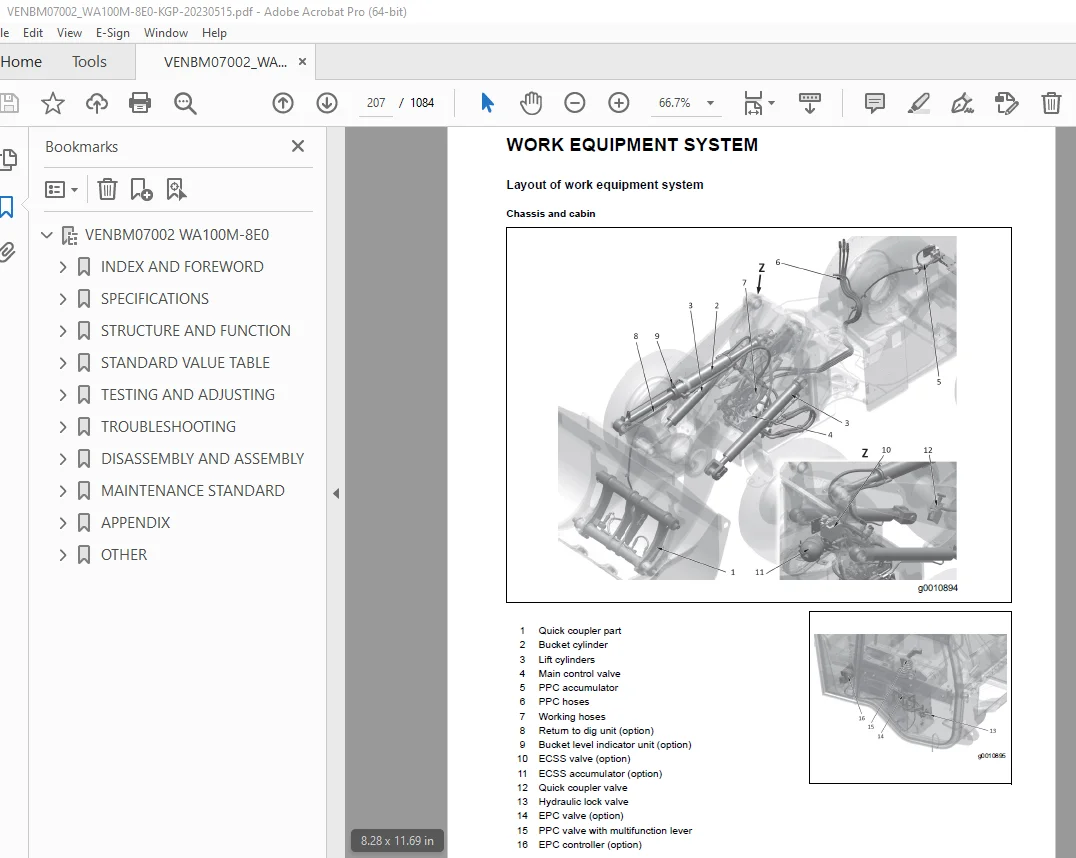
WORK EQUIPMENT SYSTEM 207
Layout of work equipment system 207
WORK EQUIPMENT LOCK SYSTEM 209
ECSS 210
Function of ECSS 210
Operation of ECSS 210
RETURN TO DIG (option) 211
Structure 211
Function 211
Main control valve 212
EPC valve 212
PPC accumulator 212
PPC valve 213
Structure 213
Function 214
Operation 214
Loader Linkage with quick-coupler 215
STEERING SYSTEM 217
STEERING COLUMN 218
Structure of steering column 218
General view 218
PRIORITY VALVE 221
ORBIT-ROLL-VALVE 222
STEERING RELIEF VALVE 223
BRAKE SYSTEM 224
LAYOUT DRAWING OF BRAKE SYSTEM 224
SERVICE BRAKE ASSEMBLY 225
Function 225
PARKING BRAKE ASSEMBLY 226
STRUCTURE OF BRAKE SYSTEM 227
20km/h without SpeedControl 227
20km/h or 40km/h with SpeedControl 228
UNDERCARRIAGE AND FRAME 229
Rear axle mount 230
FRAME, AXLE MOUNT AND CENTER HINGE PIN 231
TIRE 232
Structure of radial tire 232
General view 232
Structure 232
Structure of bias tire 233
General view 233
Structure 233
WORK EQUIPMENT 234
STRUCTURE OF WORK EQUIPMENT 234
STRUCTURE OF BUCKET 235
General view and sectional view 235
CAB AND ITS ATTACHMENTS 236
ROPS FOPS CAB 236
Structure of ROPS FOPS cab 236
Function of ROPS FOPS cab 237
CAB MOUNT 238
Structure of cab mount 238
General view 238
Function of cab mount 238
STANDARD VALUE TABLE 249
ABBREVIATION LIST 250
List of abbreviations used in the text 250
List of abbreviations used in the circuit diagrams 255
STANDARD VALUE TABLE 256
Standard value table for engine 256
Standard value table for chassis 257
TEST CERTIFICATE 259
TESTING AND ADJUSTING 261
ABBREVIATION LIST 265
List of abbreviations used in the text 265
List of abbreviations used in the circuit diagrams 270
TEST ENGINE WITH SOFTWARE TOOL 271
CONNECTION OF A COMPUTER TO THE MACHINE 271
ENGINE AND COOLING SYSTEM 273
TEST ENGINE SPEED 273
Method for testing engine speed 273
Method for testing engine low idle speed 273
Method for testing engine high idle speed 274
Method for testing engine speed HST stall 275
Method for testing engine speed at hydraulic stall 276
Method for testing engine speed at full stall (HST stall and hydraulic stall) 277
TEST EXHAUST GAS COLOUR 278
Testing tool for exhaust gas colour 278
METHOD FOR TESTING EXHAUST GAS COLOUR BY HANDY SMOKE CHECKER 279
TEST AND ADJUST VALVE CLEARANCE 280
METHOD FOR TESTING AND ADJUSTINGVALVE CLEARANCE 281
TEST COMPRESSION PRESSURE 284
METHOD FOR TESTING COMPRESSION PRESSURE 285
Compression pressure inspection procedures 285
Injector reassembly procedures 287
TEST ENGINE OIL PRESSURE 290
METHOD FOR TESTING ENGINE OIL PRESSURE 290
METHOD FOR BLEEDING AIR FROM FUEL SYSTEM 292
TEST FUEL CIRCUIT FOR LEAKAGE 293
METHOD FOR TESTING FUEL CIRCUIT FOR LEAKAGE 293
Testing method of fuel circuit for leakage at engine stopped 293
Testing method of fuel circuit for leakage at engine low idle 294
Testing method of fuel circuit for leakage at engine high idle 294
HANDLE NO-INJECTION CRANKING OPERATION 295
TEST DOC, SCR AND MUFFLER STACK FOR LOOSENESS AND DAMAGE 296
METHOD FOR TESTING DOC, SCR AND MUFFLER STACK FOR LOOSENESS AND DAMAGE 296
TEST INSTALLED CONDITION OF CYLINDER HEADS AND MANIFOLDS 297
METHOD FOR TESTING INSTALLED CONDITION OF CYLINDER HEADS AND MANIFOLDS 297
TEST ENGINE PIPING FOR DAMAGE AND LOOSENESS 298
METHOD FOR TESTING ENGINE PIPING FOR DAMAGE AND LOOSENESS 298
TEST AND ADJUST AIR CONDITIONER COMPRESSOR BELT TENSION 299
METHOD FOR CHECKING AIR CONDITIONER COMPRESSOR BELT 299
METHOD FOR ADJUSTING AIR CONDITIONER COMPRESSOR BELT 300
TEST ALTERNATOR BELT 301
METHOD FOR TESTING ALTERNATOR BELT 301
CLEAN AdBlue/DEF TANK 302
METHOD FOR CLEANING AdBlue/DEF TANK 302
POWER TRAIN 306
TEST AND ADJUST HST PRESSURE CUT OFF 306
TEST DRIVE SHAFT FOR LOOSENESS, BACKLASH, AND DAMAGE 308
METHOD FOR TESTING DRIVE SHAFT FOR LOOSENESS, BACKLASH, AND DAMAGE 308
STEERING SYSTEM 309
Operating time for steering wheel 309
Operating force of steering wheel 310
TEST AND ADJUST STEERING CIRCUIT OIL PRESSURE 310
METHOD FOR TESTING STEERING CIRCUIT OIL PRESSURE 311
METHOD FOR ADJUSTING STEERING CIRCUIT OIL PRESSURE 312
BLEED AIR FROM STEERING CYLINDER CIRCUIT 313
METHOD FOR BLEEDING AIR FROM STEERING CYLINDER CIRCUIT 313
BLEED AIR FROM BRAKE CIRCUIT 314
TEST BRAKING PERFORMANCE 316
MEASURING THE STOPPING DISTANCE 316
TEST AND ADJUST BRAKE PEDAL 317
TEST WEAR OF WHEEL BRAKE DISC 318
TEST PARKING BRAKE PERFORMANCE 319
HYDRAULIC SYSTEM 320
Releasing the remaining pressure in ECSS 321
TEST AND ADJUST WORK EQUIPMENT PRESSURE 322
TEST WORK EQUIPMENT PPC PRESSURE 323
BLEED AIR FROM WORK EQUIPMENT PPC CIRCUIT 324
TESTING AND ADJUSTING COOLING FAN SPEED 325
TEST ECSS ACCUMULATOR NITROGEN GAS PRESSURE 327
METHOD FOR TESTING THE ECSS ACCUMULATOR NITROGEN GAS PRESSURE 328
METHOD FOR CHARGING THE ECSS ACCUMULATOR WITH NITROGEN GAS 329
ELECTRICAL SYSTEM 331
SET AND ADJUST EACH EQUIPMENT 331
SET AND OPERATE MACHINE MONITOR 332
Switch panel 332
OPERATOR MODE 335
Setting usage limitation (password) 335
Change password 336
SERVICE MODE 338
Table of self-define monitoring 341
ABNORMALITY RECORD MENU 354
DEFAULT MENU 365
ADJUSTMENT MENU 370
HANDLE BATTERY DISCONNECT SWITCH 373
TEST DIODES 376
TROUBLESHOOTING 379
ABBREVIATION LIST 383
List of abbreviations used in the text 383
List of abbreviations used in the circuit diagrams 388
RELATED INFORMATION ON TROUBLESHOOTING 389
GENERAL TROUBLESHOOTING POINTS 389
SEQUENCE OF EVENTS IN TROUBLESHOOTING 391
CHECKS BEFORE TROUBLESHOOTING 393
Engine, lubricating oil, coolant, and AdBlue/DEF 393
Hydraulic and mechanical equipment 393
Electric equipment 394
Exterior 394
Interior 394
INSPECTION PROCEDURE BEFORE TROUBLESHOOTING 395
WALK-AROUND CHECK 395
PROCEDURE FOR TESTING AND TROUBLESHOOTING 397
INFORMATION DESCRIBED IN TROUBLESHOOTING TABLE 398
CONNECTOR LOCATION LIST 400
CONNECTOR CONTACT IDENTIFICATION 409
SPARE FUSES AND RELAY 446
USB socket on central electric board (CEB) 451
FAILURE CODES TABLE 454
TROUBLESHOOTING BY FAILURE CODE (DISPLAY OF HST-CONTROLLER CODE) 479
POWER ON 480
8 2 1 Documentation of Power On (PwrOn) 480
8 2 1 – 2 Interface 480
8 2 1 – 3 Description 481
8 2 1 – 3 3 State 2: Check sensor supply voltages 484
8 2 1 – 3 4 State 3: Check hardware monitoring errors 484
8 2 1 – 3 5 State 4: Check first application specific start condition 484
8 2 1 – 3 6 State 5: Check central switch 484
8 2 1 – 3 7 State 6: Configure safouts 485
8 2 1 – 3 8 State 7: Check safouts 485
8 2 1 – 3 9 State 8: Check diesel engine speed 485
8 2 1 – 3 10 State 9: Enable sensor supply monitoring 486
8 2 1 – 3 11 State 10: Check hardware monitoring errors 486
8 2 1 – 3 12 State 11: Check second applications specific start condition 486
8 2 1 – 3 12 State 11: Check second applications specific start condition 486
8 2 1 – 3 13 State 12: Run 486
8 2 1 – 3 14 Diagnosis Configuration Notes 487
8 2 1 – 4 Input Signals 487
8 2 1 – 5 Parameters 488
8 2 1 – 6 Output Signals 488
8 2 1 – 7 Error Information 488
Abbreviations for Failure Code (HST-controller) 490
FAILURE CODE (#R0CIB) 491
FAILURE CODE (#R0CKB) 492
FAILURE CODE (#R0CLB) 493
FAILURE CODE (#R0CMB) 494
FAILURE CODE (#R0CPV) 495
FAILURE CODE (#R0CQB) 496
FAILURE CODE (#R0CRB) 497
FAILURE CODE (#R0CSB) 498
FAILURE CODE (#R0CTB) 499
FAILURE CODE (#R0CWB) 500
FAILURE CODE (#R0JLB) 501
FAILURE CODE (#R0JMB) 502
FAILURE CODE (#R0JNB) 503
FAILURE CODE (#R0JOB) 504
FAILURE CODE (#R0JPB) 505
FAILURE CODE (#R0QR2) 506
FAILURE CODE (#R0QS2) 507
FAILURE CODE (#R0QT4) 508
FAILURE CODE (#R0QU3) 509
FAILURE CODE (#R0QV4) 510
FAILURE CODE (#R0QY4) 511
FAILURE CODE (#R0QZ4) 512
FAILURE CODE (#R0R0V) 513
FAILURE CODE (#R0R1V) 514
FAILURE CODE (#R0SHV) 515
FAILURE CODE (#R0SIV) 516
FAILURE CODE (#R0SJV) 517
FAILURE CODE (#R0SKV) 518
FAILURE CODE (#R0SLV) 519
FAILURE CODE (#R0XU2) 520
FAILURE CODE (#R0XU3) 521
FAILURE CODE (#R0XU4) 522
FAILURE CODE (#R0XUB) 523
FAILURE CODE (#R0XV2) 524
FAILURE CODE (#R0XV3) 525
FAILURE CODE (#R0XV4) 526
FAILURE CODE (#R0XVB) 527
FAILURE CODE (#R0XW2) 528
FAILURE CODE (#R0XW3) 529
FAILURE CODE (#R0XW4) 530
FAILURE CODE (#R0XWB) 531
FAILURE CODE (#R0XY2) 532
FAILURE CODE (#R0XY3) 533
FAILURE CODE (#R0XY4) 534
FAILURE CODE (#R0XYB) 535
FAILURE CODE (#R14W2) 536
FAILURE CODE (#R14WB) 537
FAILURE CODE (#R14X2) 538
FAILURE CODE (#R14XB) 539
FAILURE CODE (#R14Y2) 540
FAILURE CODE (#R14YB) 541
FAILURE CODE (#R14Z2) 542
FAILURE CODE (#R14ZB) 543
FAILURE CODE (#R1502) 544
FAILURE CODE (#R1504) 545
FAILURE CODE (#R150B) 546
FAILURE CODE (#R1512) 547
FAILURE CODE (#R151B) 548
FAILURE CODE (#R15C2) 549
FAILURE CODE (#R15C3) 550
FAILURE CODE (#R15C4) 551
FAILURE CODE (#R15CB) 552
FAILURE CODE (#R15CV) 553
FAILURE CODE (#R1KWJ) 554
FAILURE CODE (#R1KWV) 555
FAILURE CODE (#R1QB2) 556
FAILURE CODE (#R1QBB) 557
FAILURE CODE (#R1QBV) 558
FAILURE CODE (#R1QD2) 559
FAILURE CODE (#R1QDB) 560
FAILURE CODE (#R1QE2) 561
FAILURE CODE (#R1QEB) 562
FAILURE CODE (#R1QEV) 563
FAILURE CODE (#R1XEB) 564
FAILURE CODE (#R1XFB) 565
FAILURE CODE (#R1XG2) 566
FAILURE CODE (#R1XGB) 567
FAILURE CODE (#R1XJB) 568
FAILURE CODE (#R20XB) 569
FAILURE CODE (#R20YB) 570
FAILURE CODE (#R268B) 571
FAILURE CODE (#R2693) 572
FAILURE CODE (#R2694) 573
FAILURE CODE (#R2695) 574
FAILURE CODE (#R269B) 575
FAILURE CODE (#R26AB) 576
FAILURE CODE (#R26B3) 577
FAILURE CODE (#R26B4) 578
FAILURE CODE (#R26B5) 579
FAILURE CODE (#R26BB) 580
FAILURE CODE (#R26OB) 581
FAILURE CODE (#R26P3) 582
FAILURE CODE (#R26P4) 583
FAILURE CODE (#R26P5) 584
FAILURE CODE (#R26PB) 585
FAILURE CODE (#R280B) 586
FAILURE CODE (#R2813) 587
FAILURE CODE (#R2814) 588
FAILURE CODE (#R2815) 589
FAILURE CODE (#R281B) 590
FAILURE CODE (#R2BKB) 591
FAILURE CODE (#R2J92) 592
FAILURE CODE (#R2J9V) 593
FAILURE CODE (#R2JK2) 594
FAILURE CODE (#R2JK9) 595
FAILURE CODE (#R2JKB) 596
FAILURE CODE (#R2JL2) 597
FAILURE CODE (#R2JL9) 598
FAILURE CODE (#R2JLB) 599
FAILURE CODE (#R2JM2) 600
FAILURE CODE (#R2JM9) 601
FAILURE CODE (#R2JMB) 602
FAILURE CODE (#R2JN2) 603
FAILURE CODE (#R2JN9) 604
FAILURE CODE (#R2JNB) 605
FAILURE CODE (#R2JO2) 606
FAILURE CODE (#R2JO9) 607
FAILURE CODE (#R2JOB) 608
FAILURE CODE (#R2JP2) 609
FAILURE CODE (#R2JP9) 610
FAILURE CODE (#R2JPB) 611
FAILURE CODE (#R2JR2) 612
FAILURE CODE (#R2JR9) 613
FAILURE CODE (#R2JRB) 614
FAILURE CODE (#R2JS2) 615
FAILURE CODE (#R2JS9) 616
FAILURE CODE (#R2JSB) 617
FAILURE CODE (#R2JT2) 618
FAILURE CODE (#R2JT9) 619
FAILURE CODE (#R2JTB) 620
FAILURE CODE (#R2JU2) 621
FAILURE CODE (#R2JU9) 622
FAILURE CODE (#R2JUB) 623
TROUBLESHOOTING OF ELECTRICAL SYSTEM (E- MODE) 624
TROUBLESHOOTING FOR HYDRAULIC AND MECHANICAL SYSTEMS (H MODE) 642
TROUBLESHOOTING OF ENGINE (S-MODE) 651
S-4 ENGINE STARTABILITY IS POOR 655
S-9 EXHAUST SMOKE IS BLACK 663
S-12 FUEL CONSUMPTION IS EXCESSIVE 667
S-14 OIL PRESSURE DROPS 669
S-18 UNUSUAL NOISE IS HEARD 673
S-19 VIBRATION IS EXCESSIVE 674
DISASSEMBLY AND ASSEMBLY 681
ABBREVIATION LIST 683
List of abbreviations used in the text 683
RELATED INFORMATION ON DISASSEMBLY AND ASSEMBLY 688
HOW TO READ THIS MANUAL 688
Reading the work procedures 688
Reading the symbols 688
Reading the signal word 689
Reading the unit 689
COATING MATERIALS LIST 690
Adhesive 690
Liquid gasket 691
Molybdenum disulfide lubricant 691
Seizure prevention compound 692
Grease 692
Primer 693
Adhesive 693
Caulking material 693
ENGINE AND COOLING SYSTEM 694
REMOVE AND INSTALL SUPPLY PUMP ASSEMBLY 694
Removal of supply pump assembly 694
Reassembly of supply pump 696
REMOVE AND INSTALL INJECTOR ASSEMBLY 698
Removal of injector 698
Reassembly of injector 699
REMOVE AND INSTALL CYLINDER HEAD ASSEMBLY 702
Disassembly of Cylinder Head 702
Cleaning of cylinder head components 713
Inspection of cylinder head components 714
Reassembly of cylinder head 720
REMOVE AND INSTALL EGR VALVE ASSEMBLY 727
Remove and install EGR cooler assembly 727
REMOVE AND INSTALL STARTING MOTOR ASSEMBLY 728
Removal of Starter Motor 728
Disassembly of Starter Motor 728
Reassembly of Starter Motor 731
Reassembly of Starter Motor 732
REMOVE AND INSTALL AdBlue/DEF TANK SENSOR FLANGE ASSEMBLY 733
METHOD FOR REMOVING AdBlue/DEF TANK SENSOR FLANGE ASSEMBLY 733
METHOD FOR INSTALLING AdBlue/DEF TANK SENSOR FLANGE ASSEMBLY 736
REMOVE AND INSTALL AdBlue/DEF TANK SENSOR 740
METHOD FOR REMOVING AdBlue/DEF TANK SENSOR 740
METHOD FOR INSTALLING AdBlue/DEF TANK SENSOR 742
REMOVE AND INSTALL AdBlue/DEF TANK STRAINER 749
METHOD FOR REMOVING AdBlue/DEF TANK STRAINER 749
METHOD FOR INSTALLING AdBlue/DEF TANK STRAINER 750
REMOVE AND INSTALL DOC and SCR ASSEMBLY 751
METHOD FOR REMOVING DOC ASSEMBLY 752
REMOVE AND INSTALL AdBlue/DEF INJECTOR 762
Method for removing AdBlue/ DEF injector 764
Method for installing AdBlue/DEF injector 766
REMOVE AND INSTALL AdBlue/DEF PUMP 768
Method for removing AdBlue/DEF pump 768
Method for installing AdBlue/DEF pump 771
REMOVE AND INSTALL AdBlue/DEF HOSE 773
Method for removing AdBlue/DEF hose 773
POWER TRAIN 780
PUMP FOR STEERING, WORK EQUIPMENT, COOLING FAN AND HIGH FLOW 780
Removal of the standard pump (steering, work equipment and cooling fan) 780
Removal of the HighFlow pump (steering, work equipment, cooling fan and HighFlow) 780
Installation of hydraulic pump assembly (standard and high flow) 781
ARTICULATED JOINT ASSEMBLY 782
Removal of articulation joint assembly 782
Installation of articulation joint assembly 782
HST MOTOR ASSEMBLY 783
Removal of HST motor assembly 783
Installation of variable motor assembly 784
HST PUMP ASSEMBLY 785
Removal of HST pump assembly 785
Installation of HST pump assembly 786
GEARBOX (TRANSFER ASSEMBLY) 787
PRECAUTIONS FOR ASSEMBLY AND DISASSEMBLY 787
Safety precautions 787
HYDRAULIC GEAR CONTROL 788
Exploded view 788
Disassembly 789
Assembly 792
HYDRAULIC GEAR CONTROL – VALVE ON BOARD 797
Exploded view 797
Disassembly 798
Assembly 801
HYDRAULIC GEAR CONTROL (CONTACTLESS SENSOR) 807
Exploded view 807
Disassembly 808
Assembly 812
COUNTER-REVOLUTION SENSOR 818
Replacement 818
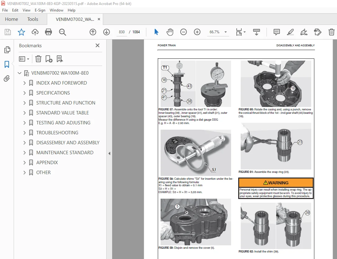
SHORT FLANGED REDUCTION GEAR 819
Exploded view 819
Disassembly 820
Assembly 828
REMOVE AND INSTALL AIR CONDITIONER COMPRESSOR BELT 841
REMOVE AND INSTALL ALTERNATOR BELT 842
GEARBOX INSTALLATION 843
Disassembly 843
INTEGRATED GEAR BOX 846
Exploded view 846
Disassembly 847
Assembly 854
REMOVE AND INSTALL ALTERNATOR ASSEMBLY 863
SPECIAL TOOLS 864
REAR AXLE ASSEMBLY 867
Removal of rear axle assembly 867
Installation of rear axle assembly 869
FRONT AXLE ASSEMBLY 870
Removal of front axle assembly 870
Installation of front axle assembly 871
PRECAUTIONS FOR ASSEMBLY AND DISASSEMBLY OF AXLE COMPONENTS 872
SAFETY PRECAUTIONS 872
CHECKING WEAR AND REPLACING THE BRAKING DISCS 873
Exploded view 873
Disassembly 874
Assembly 876
Special tools 878
DISASSEMBLY AND ASSEMBLY AXLE HOUSING ASSEMBLY 879
PLANETARY REDUCTION AND AXLE SHAFT 879
Exploded view 879
Disassembly 880
Assembly 884
Special tools 888
BEVEL PINION 891
Exploded view 891
Disassembly 892
Assembly 894
Special tools 901
DISASSEMBLY AND ASSEMBLY DIFFERENTIAL ASSEMBLY 907
DIFFERENTIAL UNIT 907
Exploded view 907
Disassembly 908
Assembly 910
Special tools 912
MANUAL EMERGENCY RELEASE 913
Exploded view 913
Release 914
Adjustment 915
MECHANICAL PARKING BRAKE 916
Exploded view 916
Disassembly 917
Assembly 919
NORMAL DIFFERENTIAL UNIT 921
Exploded view 921
Disassembly 922
Assembly 924
Special tools 927
LIMITED SLIP DIFFERENTIAL UNIT (25% AND 45%) 930
Exploded view 930
Disassembly 931
Assembly 934
Special tools 937
HYDRAULIC DIFFERENTIAL LOCK 940
Exploded view 940
Disassembly 941
Assembly 944
Special tools 946
WORK EQUIPMENT SYSTEM 947
REMOVE AND INSTALL MAIN VALVE ASSEMBLY 947
Removal of main control valve assembly 947
Installation of main control valve assembly 948
REMOVE AND INSTALL PILOT VALVE ASSEMBLY 949
Removal of pilot control valve assembly 949
Removal of standard multifunction lever 951
Removal of optional multifunction lever 952
Assembly of pilot control valve 952
ELECTRICAL SYSTEM 954
REMOVE AND INSTALL ENGINE CONTROLLER ASSEMBLY 954
Remove and install central electric board (CEB) 954
Method for removing engine controller assembly 955
REMOVE AND INSTALL HST CONTROLLER ASSEMBLY 957
Method for removing the cover of the console 957
REMOVE AND INSTALL MACHINE MONITOR ASSEMBLY 958
Method for removing machine monitor assembly 958
Method for installing machine monitor assembly 961
REMOVE AND INSTALL EPC CONTROLLER ASSEMBLY 962
Method for removing the cover of the console 962
MAINTENANCE STANDARD 963
ABBREVIATION LIST 965
List of abbreviations used in the text 965
List of abbreviations used in the circuit diagrams 970
ENGINE AND COOLING 971
MAINTENANCE STANDARD OF ENGINE MOUNT 971
MAINTENANCE STANDARD OF DAMPER 972
MAINTENANCE STANDARD OF COOLING FAN MOTOR 973
HYDRAULIC SYSTEM 974
CAB AND ITS ATTACHMENTS 978
Cabin – adjustment 978
APPENDIX 979
ABBREVIATION LIST 981
List of abbreviations used in the text 981
List of abbreviations used in the circuit diagrams 986
AIR CONDITIONER SYSTEM 987
PRECAUTIONS FOR REFRIGERANT 987
AIR CONDITIONER COMPONENT 988
Specifications of air conditioner 988
CONFIGURATION AND FUNCTION OF REFRIGERATION CYCLE 989
OUTLINE OF REFRIGERATION CYCLE 990
Compression (Compressor) 990
Condensation (Condenser) 990
Expansion (Expansion valve) 990
Evaporation (Evaporator) 991
Relation between refrigerant and cooling trouble 991
AIR CONDITIONER TROUBLESHOOTING CHART 993
Cooling trouble 993
Heating trouble 993
CONNECTION OF SERVICE TOOL 994
METHOD FOR CONNECTING SERVICE TOOL 995
PRECAUTIONS FOR DISCONNECTING AND CONNECTING HOSES AND TUBES IN AIR CONDITIONER PIPINGS 996
Precautions for disconnection 996
Precautions for connection 997
HANDLE COMPRESSOR OIL 998
Management of compressor oil (SANDEN: SP-10 for use with R134a) 998
Filling of compressor oil 998
The quantity of compressor oil when the compressor is replaced 999
OTHER 1001
HYDRAULIC CIRCUIT DIAGRAM (SERIAL NUMBERS: H11201 – AND UP) 1005
WIRING DIAGRAMS (SERIAL NUMBERS: H11201 – AND UP) 1007
Contents 1007
1-0 SYMBOLS SUMMARY, ABBREVIATIONS 1008
1-1 HARNESS ARRANGEMENT EXPLANATION 1009
1-2 CAN BUS SUMMARY 1010
2-0 POWER SUPPLY, STARTER SWITCH 1011
2-1 GROUNDING 1012
2-2 RELAYB , STARTER, ALTERN , BATTERY, GLOW PLUG0 1013
2-3 DEF + ECU RELAYS 1014
3-0 AFTERTREATMENT SYSTEM 1015
3-1 ECU, AIR CLEANER, WATER SEPA , FUEL FEED PUMP 1016
3-2 DPF SENS , OIL PRESS , TRAVEL PED , HEATER LINES 1017
4-0 MONITOR, MAIN CONTROLLER, STEERING PRESSURE 1018
4-1 KOMTRAX CTRL, SERVICE CONNECTOR 1019
4-2 FLUID-SENSORS (OIL, FUEL, COOLANT), SPEED SENS 1020
5-0 SEC ENG STOP, IMMOBILIZER, DRIVING FUNCT 1021
5-1 SPEED CONTROLLER 40KPH 1022
5-2 HST CONTROLLER INPUTS 1023
5-3 CREEP, HIGH FLOW 1024
6-0 FAN DRIVE, REVERSE FAN 1025
7-0 AIR CONDITIONER, OPERATORS SEATI 1026
7-1 WASHER, WIPER, REAR WINDOW HEATER, HORN 1027
8-0 LIGHTING 1028
8-1 FLASHER 1029
8-2 REAR LIGHT, LICENSE PL , BACKUP AL , REAR FLASH 1030
8-3 WORK LAMPS 1031
8-4 INTERIOR LAMP, ROTATING BEACON, PLUG BOX 1032
9-0 3RD AND 4TH HYDRAULIC CIRCUIT EPC INPUT 1033
9-1 3RD AND 4TH HYDRAULIC CIRCUIT EPC OUTPUT 1034
10-0 DRIVING RANGE, ECSS, OVER CENTER V , AUTO INCH 1035
10-1 RETURN TO DIG, QUICK COUPLER, DIFF LOCK 1036
10-2 RADIO, CLS, BLANK OPT , DPF REGEN SW, MAINT SW 1037
W1 WIRING HARNESS LIST 1038
W2 CONNECTOR LIST 1 1039
W2 CONNECTOR LIST 2 1040
W2 CONNECTOR LIST 3 1041
W2 CONNECTOR LIST 4 1042
W2 CONNECTOR LIST 5 1043
W2 CONNECTOR LIST 6 1044
W3 PIN LOCATION LIST 1 1045
W3 PIN LOCATION LIST 2 1046
W3 PIN LOCATION LIST 3 1047
W3 PIN LOCATION LIST 4 1048
W3 PIN LOCATION LIST 5 1049
W3 PIN LOCATION LIST 6 1050
W3 PIN LOCATION LIST 7 1051
W3 PIN LOCATION LIST 8 1052
W3 PIN LOCATION LIST 9 1053
W3 PIN LOCATION LIST 10 1054
W3 PIN LOCATION LIST 11 1055
W3 PIN LOCATION LIST 12 1056
W3 PIN LOCATION LIST 13 1057
W3 PIN LOCATION LIST 14 1058
W3 PIN LOCATION LIST 15 1059
W3 PIN LOCATION LIST 16 1060
W3 PIN LOCATION LIST 17 1061
W3 PIN LOCATION LIST 18 1062
W3 PIN LOCATION LIST 19 1063
W3 PIN LOCATION LIST 20 1064
W3 PIN LOCATION LIST 21 1065
W3 PIN LOCATION LIST 22 1066
W3 PIN LOCATION LIST 23 1067
W3 PIN LOCATION LIST 24 1068
W3 PIN LOCATION LIST 25 1069
W3 PIN LOCATION LIST 26 1070
W3 PIN LOCATION LIST 27 1071
W3 PIN LOCATION LIST 28 1072
W3 PIN LOCATION LIST 29 1073
W3 PIN LOCATION LIST 30 1074
W3 PIN LOCATION LIST 31 1075
W3 PIN LOCATION LIST 32 1076
W3 PIN LOCATION LIST 33 1077
PARTS LIST 1 1078
PARTS LIST 2 1079
PARTS LIST 3 1080
Connector diagram 1081
Connector diagram 1 1081
Connector diagram 2 1082
Connector diagram 3 1083
Connector table for the operator‘s cab wiring harness (Part 1/2) 1083
Connector diagram 4 1084
Connector table for operator‘s cab wiring harness (Part 2/2) 1084
DESCRIPTION:
Komatsu WA100M-8E0 Wheel Loader Shop Manual VENBM07002 – PDF DOWNLOAD
Model: Serial number:
WA100M-8E0 H11201 AND UP
FOREWORD, SAFETY, BASIC INFORMATION:
HOW TO READ THE SHOP MANUAL:
• Some of the attachments and options described in this shop manual may not be available in some areas. If
they are required, consult your Komatsu distributor.
• The materials and specifications are subject to change without notice.
• Shop Manuals are available for “machine part” and “engine part”. For the engine unit, see the shop manual
for the machine which has the same engine model.
• Actual machine may differ from the images which are contained in this manual. A typical model is shown in
the illustrations of this shop manual.
Composition of the shop manual
This shop manual contains technical information necessary to perform services in workshops. It is divided into
the following chapters for the ease of use.
00 INDEX AND FOREWORD
This section describes the index, foreword, safety, and basic information.
01 SPECIFICATIONS
This section describes the specifications of the machine.
10 STRUCTURE AND FUNCTION
This section describes the structure and operation of each component with respect to each system. “STRUCTURE
AND FUNCTION” is helpful in not only understanding the structure of each component but performing
troubleshooting.
20 STANDARD VALUE TABLE
This section describes the standard values for new machine and failure criteria for testing and adjusting, and
troubleshooting. Use the standard values table to check the standard values for testing and adjusting, and judge
troubles in troubleshooting.
30 TESTING AND ADJUSTING
This section describes the measuring tools and measuring methods for testing and adjusting as well as the adjusting
method of each part. The standard values and repair limit for TESTING AND ADJUSTING are described
in “STANDARD VALUE TABLE”.
40 TROUBLESHOOTING
This section describes troubleshooting of failure part and its remedy method on the occurrence of the failure.
Descriptions of troubleshooting are sorted by failure mode.
50 DISASSEMBLY AND ASSEMBLY
This section describes the special tools, work procedures, and safety precautions necessary for removal, installation,
disassembly, and assembly of the components and parts. In addition, tightening torques, quantity, and
weight of the coating materials, lubricants, and coolant necessary to these works are shown.
60 MAINTENANCE STANDARD
This section describes the maintenance standard value of each component. The maintenance standard shows
the criteria and remedies for disassembly and assembly.
80 THE OTHER INFORMATION
This section describes the structure and function, testing and adjusting, and troubleshooting for all of the other
components or equipment which cannot be separately classified in the appendix.
90 Circuit diagrams
This section describes hydraulic circuit diagrams and electrical circuit diagrams.
S.V 30/12/24


