Komatsu WA100M-8 Wheel Loader Shop Manual VENBM06001 PDF
$34.95
Komatsu WA100M-8 Wheel Loader Shop Manual VENBM06001 – PDF DOWNLOAD
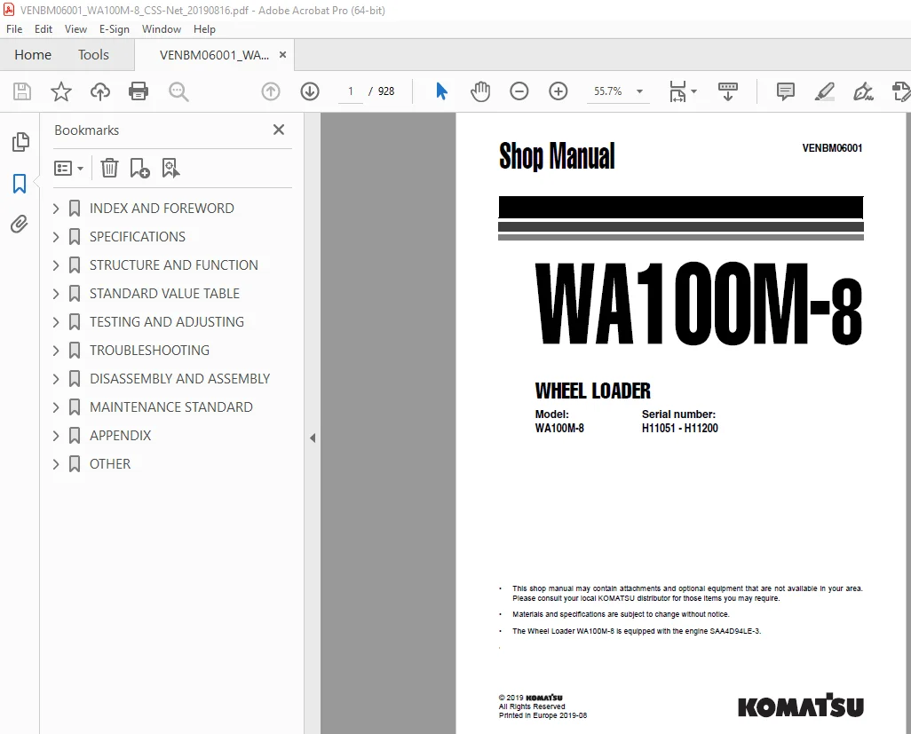
Model: Serial number:
WA100M-8 H11051 – H11200
Description
Komatsu WA100M-8 Wheel Loader Shop Manual VENBM06001 – PDF DOWNLOAD
FILE DETAILS:
Komatsu WA100M-8 Wheel Loader Shop Manual VENBM06001 – PDF DOWNLOAD
Language : English
Pages : 928
Downloadable : Yes
File Type : PDF
IMAGES PREVIEW OF THE MANUAL:
TABLE OF CONTENTS:
Komatsu WA100M-8 Wheel Loader Shop Manual VENBM06001 – PDF DOWNLOAD
Model: Serial number:
WA100M-8 H11051 – H11200
INDEX AND FOREWORD 3
ABBREVIATION LIST 4
List of abbreviations used in the text 4
List of abbreviations used in the circuit diagrams 9
FOREWORD, SAFETY, BASIC INFORMATION 10
HOW TO READ THE SHOP MANUAL 10
Composition of the shop manual 10
Symbols 12
Signal word 12
Unit 12
SAFETY NOTICE FOR OPERATION 13
Safety matters 13
General precautions 14
Precautions for preparatory work 15
Precautions during work 15
Precautions for slinging work and making signals 17
Precautions for using mobile crane 20
Precautions for using overhead traveling crane 20
Selecting wire ropes 21
PRECAUTIONS TO PREVENT FIRE 23
Fire caused by fuel, oil, coolant or window washer fluid 23
Fire caused by accumulation or attachment of flammable material 23
Fire coming from electric wiring 23
Fire caused by piping 24
Fire around the machine due to highly heated exhaust gas 24
Explosion caused by lighting equipment 24
ACTIONS IF FIRE OCCURS 25
PRECAUTIONS FOR DISPOSING OF WASTE MATERIALS 26
ACTIONS TAKEN TO MEET EXHAUST GAS REGULATIONS 27
About DEF 27
PRECAUTIONS FOR DEF 28
General character and precautions for handling 28
Precautions for adding 28
Precautions for storing 28
Precautions for fire hazard and leakage 28
The other precautions 29
STORE AdBlue/DEF 30
Handling AdBlue/DEF in cold weather 30
PRECAUTIONS FOR HANDLING HYDRAULIC EQUIPMENT 31
Select an appropriate workplace 31
Disassembly and maintenance work in the field 31
Sealing of openings (prevention of flowing out of oil) 31
Preventing intrusion of foreign materials during refilling 32
Replacing hydraulic oil while its temperature is high 32
Avoid reusing the hydraulic oil and lubricating oil 32
Flushing operation 33
Cleaning operation 33
PRECAUTIONS FOR DISCONNECTION AND CONNECTION OF PIPINGS 34
PRECAUTIONS FOR HANDLING ELECTRICAL EQUIPMENT 45
Defective contact of connectors (defective contact between male and female connectors) 45
Defective crimping or soldering of connectors 46
Disconnection in wiring 46
Water entering the connector by high-pressure jetting 46
Entry of water, dirt, or dust when disconnecting a connector 46
Oil, mud, or dust stuck to connector 47
Select an appropriate workplace 48
Sealing the opening 48
How to clean parts when dirt is stuck 48
Precautions for replacing fuel filter cartridge 48
Select an appropriate workplace 49
Sealing the opening 49
PRACTICAL USE OF KOMTRAX 50
Merit of using KOMTRAX 50
How to make a full use of KOMTRAX 51
How to operate KOMTRAX 51
Disconnecting connectors 52
Connecting connectors 53
Drying wiring harness 55
Handling controller 56
Method for disconnecting Deutsch connector 57
Method for connecting Deutsch connector 57
Method for disconnecting slide lock type connector (FRAMATOME-3, FRAMATOME-2) 58
Method for connecting slide lock type connector (FRAMATOME-3, FRAMATOME-2) 58
Method for disconnecting slide lock type connector (FRAMATOME-24) 58
Method for connecting slide lock type connector (FRAMATOME-24) 58
Method for disconnecting connector with lock to pull 59
Method for connecting connector with lock to pull 59
Method for disconnecting connector with lock to push (BOSCH-3) 60
Method for connecting connector with lock to push (BOSCH-3) 60
Method for disconnecting connector with lock to push (AMP-3) 61
Method for connecting connector with lock to push (AMP-3) 61
Method for disconnecting connector with lock to push (SUMITOMO-3) 61
Method for connecting connector with lock to push (SUMITOMO-3) 61
Method for disconnecting connector with lock to push (SUMITOMO-4) 61
Method for connecting connector with lock to push (SUMITOMO-4) 61
Method for disconnecting connector with housing to rotate 62
Method for connecting connector with housing to rotate 62
Method for connecting ring terminals and strip fuses to power stud of printed circuit boards 63
HOW TO READ ELECTRICAL WIRE CODE 64
TYPE, SYMBOL, AND MATERIAL 64
COLOR CODES TABLE 65
EXPLANATION OF TERMS FOR MAINTENANCE STANDARD 66
STANDARD DIMENSION AND TOLERANCE 66
STANDARD CLEARANCE AND STANDARD VALUE 67
STANDARD INTERFERENCE 67
REPAIR LIMIT AND ALLOWABLE VALUE OR ALLOWABLE DIMENSION 67
ALLOWABLE CLEARANCE 68
ALLOWABLE INTERFERENCE 68
STANDARD TIGHTENING TORQUE TABLE 69
CONVERSION TABLE 77
METHOD OF USING THE CONVERSION TABLE 77
EXAMPLES OF USING THE CONVERSION TABLE TO CONVERT A UNIT FROM MM TO IN 77
TEMPERATURE 81
SPECIFICATIONS 83
DIMENSIONS, WEIGHTS AND OPERATING DATA 84
SPECIFICATIONS 86
WEIGHT TABLES 87
LUBRICANTS AND OPERATING MEDIUMS 88
BASIC PROCEDURES OF MAINTENANCE 90
OIL 90
FUEL 90
COOLANT 91
GREASE 91
STORING OIL AND FUEL 91
FILTERS 92
OUTLINE OF ELECTRIC SYSTEM 92
TIGHTENING TORQUE LIST – METRIC SCREWS AND NUTS 93
STRUCTURE AND FUNCTION 95
ABBREVIATION LIST 99
List of abbreviations used in the text 99
List of abbreviations used in the circuit diagrams 104
UREA SCR SYSTEM 105
UREA SCR SYSTEM DIAGRAM 107
FUNCTION OF UREA SCR SYSTEM 108
FUNCTION OF AdBlue/DEF SYSTEM 109
AdBlue/DEF INJECTION FUNCTION 109
AdBlue/DEF PURGE FUNCTION 110
FUNCTION OF AdBlue/DEF THAWING AND PREVENTING FROM FREEZING 110
INDUCEMENT STRATEGY 111
INDUCEMENT STRATEGY WHEN THE AdBlue/DEF LEVEL IN THE TANK BECOMES LOW 111
INDUCEMENT STRATEGY WHEN ABNORMALITY IS FOUND IN THE AdBlue/DEF QUALITY OR IN THE UREA SCR SYSTEM DEVICES 113
INDUCEMENT STRATEGY WHEN ABNORMALITY IS FOUND IN THE DPF SYSTEM BY THE UREA SCR SYSTEM DEVICES 114
INDUCEMENT STRATEGY WHEN ABNORMALITY IS FOUND IN THE EGR SYSTEM BY THE UREA SCR SYSTEM DEVICES 116
INDUCEMENT STRATEGY FOR ABNORMALITY RECURRENCE WITHIN 40 HOURS 118
COMPONENT PARTS OF UREA SCR SYSTEM 119
Structure of AdBlue/DEF mixing tube 119
Function of AdBlue/DEF mixing tube 119
SCR ASSEMBLY 120
Structure of SCR assembly 120
AdBlue/DEF TANK 121
AdBlue/DEF TANK SENSOR 122
Structure of AdBlue/DEF tank sensor 122
Function of AdBlue/DEF tank sensor 122
AdBlue/DEF PUMP 123
Structure of AdBlue/DEF pump 123
AdBlue/DEF INJECTOR 124
Structure of AdBlue/DEF injector 124
Function of AdBlue/DEF injector 124
Operation of AdBlue/DEF injector 124
AdBlue/DEF HOSE 125
Structure of AdBlue/DEF hose 125
Function of AdBlue/DEF hose 125
AdBlue/DEF TANK HEATING VALVE 126
Structure of AdBlue/DEF tank heating valve 126
Function of AdBlue/DEF tank heating valve 126
Operation of AdBlue/DEF tank heating valve 127
ELECTRICAL SYSTEM 128
BOOT-UP SYSTEM 129
LAYOUT DRAWING OF BOOT-UP SYSTEM 129
AROUND THE CAB AND FLOOR 130
BATTERY DISCONNECT SWITCH 131
FUNCTION OF BATTERY DISCONNECT SWITCH 131
PREHEATING SYSTEM 133
FUNCTION OF AUTOMATIC PREHEATING SYSTEM 133
OPERATION OF AUTOMATIC PREHEATING SYSTEM 134
ENGINE SYSTEM 135
LAYOUT DRAWING OF ENGINE SYSTEM 135
COOLING SYSTEM 136
LAYOUT DRAWING OF COOLING SYSTEM 136
SPECIFICATIONS OF COOLING SYSTEM 137
COOLING FAN CONTROL SYSTEM 138
FUNCTION OF COOLING FAN CONTROL SYSTEM 139
COOLING FAN REVERSE ROTATION FUNCTION (Option) 139
COMPONENT PARTS OF COOLING SYSTEM 140
STRUCTURE OF COOLING FAN MOTOR 140
CONTROL SYSTEM 141
AROUND THE CAB AND FLOOR 142
MACHINE MONITOR SYSTEM 143
MACHINE MONITOR SYSTEM DIAGRAM 143
KOMTRAX SYSTEM 144
KOMTRAX SYSTEM DIAGRAM 144
FUNCTION OF KOMTRAX SYSTEM 144
COMPONENT PARTS OF CONTROL SYSTEM 145
MACHINE MONITOR 145
Function of KOMTRAX terminal 158
HST CONTROLLER 160
Structure of HST controller 160
Real time monitoring function 160
Self-diagnosis function 160
CAN TERMINATING RESISTOR 161
Function of CAN terminating resistor 161
ENGINE CONTROLLER 162
Real time monitoring function 162
Self-diagnosis function 162
ACCELERATOR PEDAL 163
Acceleration signal 163
Idling validation signal 163
Output Characteristics 164
HYDRAULIC SYSTEM 165
Structure of hydraulic tank 166
Specifications of hydraulic tank 166
Structure of main control valve 168
OPTIONAL HYDRAULIC SYSTEMS 171
Structure of the high flow system 171
Function of the high flow system 172
Structure of the 4th hydraulic circuit 173
Function of the 4th hydraulic circuit 174
POWER TRAIN SYSTEM 178
OPERATION OF POWER TRAIN SYSTEM 179
FUNCTION OF THE CLOSED CIRCUIT SYSTEM 181
SPECIFICATIONS OF THE HST SYSTEM 181
STRUCTURE OF THE HST SYSTEM 182
20km/h without SpeedControl 182
20km/h or 40km/h with SpeedControl 183
COMPONENT PARTS OF POWER TRAIN SYSTEM 184
Structure of drive shaft 184
Function of drive shaft 184
Structure of HST pump 185
Operation of HST pump 187
Components of HST pump 188
HST motor 192
Structure of transfer box 194
Function of transfer box 195
Structure of front axle 196
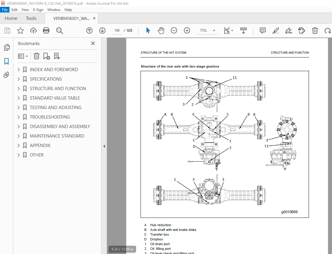
Structure of rear axle 197
Function of differential 199
Function of towing system 201
WORK EQUIPMENT SYSTEM 202
Layout of work equipment system 202
WORK EQUIPMENT LOCK SYSTEM 204
ECSS 205
Function of ECSS 205
Operation of ECSS 205
RETURN TO DIG (option) 206
Structure 206
Function 206
Main control valve 207
EPC valve 207
PPC accumulator 207
PPC valve 208
Structure 208
Function 209
Operation 209
Loader Linkage with quick-coupler 210
STEERING SYSTEM 212
STEERING COLUMN 213
Structure of steering column 213
General view 213
PRIORITY VALVE 216
ORBIT-ROLL-VALVE 217
STEERING RELIEF VALVE 218
BRAKE SYSTEM 219
LAYOUT DRAWING OF BRAKE SYSTEM 219
SERVICE BRAKE ASSEMBLY 220
Function 220
PARKING BRAKE ASSEMBLY 221
STRUCTURE OF BRAKE SYSTEM 222
20km/h without SpeedControl 222
20km/h or 40km/h with SpeedControl 223
UNDERCARRIAGE AND FRAME 224
Rear axle mount 225
FRAME, AXLE MOUNT AND CENTER HINGE PIN 226
TIRE 227
Structure of radial tire 227
General view 227
Structure 227
Structure of bias tire 228
General view 228
Structure 228
WORK EQUIPMENT 229
STRUCTURE OF WORK EQUIPMENT 229
STRUCTURE OF BUCKET 230
General view and sectional view 230
CAB AND ITS ATTACHMENTS 231
ROPS FOPS CAB 231
Structure of ROPS FOPS cab 231
Function of ROPS FOPS cab 232
CAB MOUNT 233
Structure of cab mount 233
General view 233
Function of cab mount 233
STANDARD VALUE TABLE 245
ABBREVIATION LIST 246
List of abbreviations used in the text 246
List of abbreviations used in the circuit diagrams 251
STANDARD VALUE TABLE 252
Standard value table for engine 252
Standard value table for chassis 253
TEST CERTIFICATE 255
TESTING AND ADJUSTING 257
ABBREVIATION LIST 261
List of abbreviations used in the text 261
List of abbreviations used in the circuit diagrams 266
TEST ENGINE WITH SOFTWARE TOOL 267
CONNECTION OF A COMPUTER TO THE MACHINE 267
ENGINE AND COOLING SYSTEM 269
TEST ENGINE SPEED 269
Method for testing engine speed 269
Method for testing engine low idle speed 269
Method for testing engine high idle speed 270
Method for testing engine speed HST stall 271
Method for testing engine speed at hydraulic stall 272
Method for testing engine speed at full stall (HST stall and hydraulic stall) 273
TEST EXHAUST GAS COLOUR 274
Testing tool for exhaust gas colour 274
METHOD FOR TESTING EXHAUST GAS COLOUR BY HANDY SMOKE CHECKER 275
TEST AND ADJUST VALVE CLEARANCE 276
METHOD FOR TESTING AND ADJUSTINGVALVE CLEARANCE 277
TEST COMPRESSION PRESSURE 280
METHOD FOR TESTING COMPRESSION PRESSURE 281
Compression pressure inspection procedures 281
Injector reassembly procedures 283
TEST ENGINE OIL PRESSURE 286
METHOD FOR TESTING ENGINE OIL PRESSURE 286
METHOD FOR BLEEDING AIR FROM FUEL SYSTEM 288
TEST FUEL CIRCUIT FOR LEAKAGE 289
METHOD FOR TESTING FUEL CIRCUIT FOR LEAKAGE 289
Testing method of fuel circuit for leakage at engine stopped 289
Testing method of fuel circuit for leakage at engine low idle 290
Testing method of fuel circuit for leakage at engine high idle 290
HANDLE NO-INJECTION CRANKING OPERATION 291
TEST DOC, SCR AND MUFFLER STACK FOR LOOSENESS AND DAMAGE 292
METHOD FOR TESTING DOC, SCR AND MUFFLER STACK FOR LOOSENESS AND DAMAGE 292
TEST INSTALLED CONDITION OF CYLINDER HEADS AND MANIFOLDS 293
METHOD FOR TESTING INSTALLED CONDITION OF CYLINDER HEADS AND MANIFOLDS 293
TEST ENGINE PIPING FOR DAMAGE AND LOOSENESS 294
METHOD FOR TESTING ENGINE PIPING FOR DAMAGE AND LOOSENESS 294
TEST AND ADJUST AIR CONDITIONER COMPRESSOR BELT TENSION 295
METHOD FOR CHECKING AIR CONDITIONER COMPRESSOR BELT 295
METHOD FOR ADJUSTING AIR CONDITIONER COMPRESSOR BELT 296
TEST ALTERNATOR BELT 297
METHOD FOR TESTING ALTERNATOR BELT 297
CLEAN AdBlue/DEF TANK 298
METHOD FOR CLEANING AdBlue/DEF TANK 298
POWER TRAIN 302
TEST AND ADJUST HST PRESSURE CUT OFF 302
TEST DRIVE SHAFT FOR LOOSENESS, BACKLASH, AND DAMAGE 304
METHOD FOR TESTING DRIVE SHAFT FOR LOOSENESS, BACKLASH, AND DAMAGE 304
STEERING SYSTEM 305
Operating time for steering wheel 305
Operating force of steering wheel 306
TEST AND ADJUST STEERING CIRCUIT OIL PRESSURE 306
METHOD FOR TESTING STEERING CIRCUIT OIL PRESSURE 307
METHOD FOR ADJUSTING STEERING CIRCUIT OIL PRESSURE 308
BLEED AIR FROM STEERING CYLINDER CIRCUIT 309
METHOD FOR BLEEDING AIR FROM STEERING CYLINDER CIRCUIT 309
BLEED AIR FROM BRAKE CIRCUIT 310
TEST BRAKING PERFORMANCE 312
MEASURING THE STOPPING DISTANCE 312
TEST AND ADJUST BRAKE PEDAL 313
TEST WEAR OF WHEEL BRAKE DISC 314
TEST PARKING BRAKE PERFORMANCE 315
HYDRAULIC SYSTEM 316
Releasing the remaining pressure in ECSS 317
TEST AND ADJUST WORK EQUIPMENT PRESSURE 318
TEST WORK EQUIPMENT PPC PRESSURE 319
BLEED AIR FROM WORK EQUIPMENT PPC CIRCUIT 320
TESTING AND ADJUSTING COOLING FAN SPEED 321
TEST ECSS ACCUMULATOR NITROGEN GAS PRESSURE 323
METHOD FOR TESTING THE ECSS ACCUMULATOR NITROGEN GAS PRESSURE 324
METHOD FOR CHARGING THE ECSS ACCUMULATOR WITH NITROGEN GAS 325
ELECTRICAL SYSTEM 327
SET AND ADJUST EACH EQUIPMENT 327
SET AND OPERATE MACHINE MONITOR 328
Switch panel 328
OPERATOR MODE 331
Setting usage limitation (password) 331
Change password 332
SERVICE MODE 334
Table of self-define monitoring 337
ABNORMALITY RECORD MENU 350
DEFAULT MENU 361
ADJUSTMENT MENU 366
HANDLE BATTERY DISCONNECT SWITCH 369
TEST DIODES 372
TROUBLESHOOTING 375
ABBREVIATION LIST 379
List of abbreviations used in the text 379
List of abbreviations used in the circuit diagrams 384
RELATED INFORMATION ON TROUBLESHOOTING 385
GENERAL TROUBLESHOOTING POINTS 385
SEQUENCE OF EVENTS IN TROUBLESHOOTING 387
CHECKS BEFORE TROUBLESHOOTING 389
Engine, lubricating oil, coolant, and AdBlue/DEF 389
Hydraulic and mechanical equipment 389
Electric equipment 390
Exterior 390
Interior 390
INSPECTION PROCEDURE BEFORE TROUBLESHOOTING 391
WALK-AROUND CHECK 391
PROCEDURE FOR TESTING AND TROUBLESHOOTING 393
INFORMATION DESCRIBED IN TROUBLESHOOTING TABLE 394
CONNECTOR LOCATION LIST 396
CONNECTOR CONTACT IDENTIFICATION 405
SPARE FUSES AND RELAY 442
USB socket on central electric board (CEB) 447
FAILURE CODES TABLE 450
TROUBLESHOOTING FOR HYDRAULIC AND MECHANICAL SYSTEMS (H MODE) 493
TROUBLESHOOTING OF ENGINE (S-MODE) 502
S-4 ENGINE STARTABILITY IS POOR 506
S-9 EXHAUST SMOKE IS BLACK 514
S-12 FUEL CONSUMPTION IS EXCESSIVE 518
S-14 OIL PRESSURE DROPS 520
S-18 UNUSUAL NOISE IS HEARD 524
S-19 VIBRATION IS EXCESSIVE 525
DISASSEMBLY AND ASSEMBLY 531
ABBREVIATION LIST 533
List of abbreviations used in the text 533
RELATED INFORMATION ON DISASSEMBLY AND ASSEMBLY 538
HOW TO READ THIS MANUAL 538
Reading the work procedures 538
Reading the symbols 538
Reading the signal word 539
Reading the unit 539
COATING MATERIALS LIST 540
Adhesive 540
Liquid gasket 541
Molybdenum disulfide lubricant 541
Seizure prevention compound 542
Grease 542
Primer 543
Adhesive 543
Caulking material 543
ENGINE AND COOLING SYSTEM 544
REMOVE AND INSTALL SUPPLY PUMP ASSEMBLY 544
Removal of supply pump assembly 544
Reassembly of supply pump 546
REMOVE AND INSTALL INJECTOR ASSEMBLY 548
Removal of injector 548
Reassembly of injector 549
REMOVE AND INSTALL CYLINDER HEAD ASSEMBLY 552
Disassembly of Cylinder Head 552
Cleaning of cylinder head components 563
Inspection of cylinder head components 564
Reassembly of cylinder head 570
REMOVE AND INSTALL EGR VALVE ASSEMBLY 577
Remove and install EGR cooler assembly 577
REMOVE AND INSTALL STARTING MOTOR ASSEMBLY 578
Removal of Starter Motor 578
Disassembly of Starter Motor 578
Reassembly of Starter Motor 581
Reassembly of Starter Motor 582
REMOVE AND INSTALL AdBlue/DEF TANK SENSOR FLANGE ASSEMBLY 583
METHOD FOR REMOVING AdBlue/DEF TANK SENSOR FLANGE ASSEMBLY 583
METHOD FOR INSTALLING AdBlue/DEF TANK SENSOR FLANGE ASSEMBLY 586
REMOVE AND INSTALL AdBlue/DEF TANK SENSOR 590
METHOD FOR REMOVING AdBlue/DEF TANK SENSOR 590
METHOD FOR INSTALLING AdBlue/DEF TANK SENSOR 592
REMOVE AND INSTALL AdBlue/DEF TANK STRAINER 599
METHOD FOR REMOVING AdBlue/DEF TANK STRAINER 599
METHOD FOR INSTALLING AdBlue/DEF TANK STRAINER 600
REMOVE AND INSTALL DOC and SCR ASSEMBLY 601
METHOD FOR REMOVING DOC ASSEMBLY 602
REMOVE AND INSTALL AdBlue/DEF INJECTOR 612
Method for removing AdBlue/ DEF injector 614
Method for installing AdBlue/DEF injector 616
REMOVE AND INSTALL AdBlue/DEF PUMP 618
Method for removing AdBlue/DEF pump 618
Method for installing AdBlue/DEF pump 621
REMOVE AND INSTALL AdBlue/DEF HOSE 623
Method for removing AdBlue/DEF hose 623
POWER TRAIN 630
PUMP FOR STEERING, WORK EQUIPMENT, COOLING FAN AND HIGH FLOW 630
Removal of the standard pump (steering, work equipment and cooling fan) 630
Removal of the HighFlow pump (steering, work equipment, cooling fan and HighFlow) 630
Installation of hydraulic pump assembly (standard and high flow) 631
ARTICULATED JOINT ASSEMBLY 632
Removal of articulation joint assembly 632
Installation of articulation joint assembly 632
HST MOTOR ASSEMBLY 633
Removal of HST motor assembly 633
Installation of variable motor assembly 634
HST PUMP ASSEMBLY 635
Removal of HST pump assembly 635
Installation of HST pump assembly 636
GEARBOX (TRANSFER ASSEMBLY) 637
PRECAUTIONS FOR ASSEMBLY AND DISASSEMBLY 637
Safety precautions 637
HYDRAULIC GEAR CONTROL 638
Exploded view 638
Disassembly 639
Assembly 642
HYDRAULIC GEAR CONTROL – VALVE ON BOARD 647
Exploded view 647
Disassembly 648
Assembly 651
HYDRAULIC GEAR CONTROL (CONTACTLESS SENSOR) 657
Exploded view 657
Disassembly 658
Assembly 662
COUNTER-REVOLUTION SENSOR 668
Replacement 668
SHORT FLANGED REDUCTION GEAR 669
Exploded view 669
Disassembly 670
Assembly 678
GEARBOX INSTALLATION 691
Disassembly 691
INTEGRATED GEAR BOX 694
Exploded view 694
Disassembly 695
Assembly 702
SPECIAL TOOLS 712
REAR AXLE ASSEMBLY 715
Removal of rear axle assembly 715
Installation of rear axle assembly 717
FRONT AXLE ASSEMBLY 718
Removal of front axle assembly 718
Installation of front axle assembly 719
PRECAUTIONS FOR ASSEMBLY AND DISASSEMBLY OF AXLE COMPONENTS 720
SAFETY PRECAUTIONS 720
CHECKING WEAR AND REPLACING THE BRAKING DISCS 721
Exploded view 721
Disassembly 722
Assembly 724
Special tools 726
DISASSEMBLY AND ASSEMBLY AXLE HOUSING ASSEMBLY 727
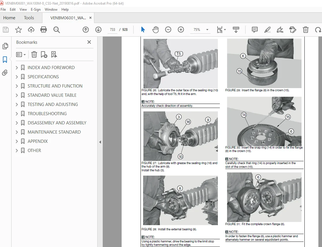
PLANETARY REDUCTION AND AXLE SHAFT 727
Exploded view 727
Disassembly 728
Assembly 732
Special tools 736
BEVEL PINION 739
Exploded view 739
Disassembly 740
Assembly 742
Special tools 749
DISASSEMBLY AND ASSEMBLY DIFFERENTIAL ASSEMBLY 755
DIFFERENTIAL UNIT 755
Exploded view 755
Disassembly 756
Assembly 758
Special tools 760
MANUAL EMERGENCY RELEASE 761
Exploded view 761
Release 762
Adjustment 763
MECHANICAL PARKING BRAKE 764
Exploded view 764
Disassembly 765
Assembly 767
NORMAL DIFFERENTIAL UNIT 769
Exploded view 769
Disassembly 770
Assembly 772
Special tools 775
LIMITED SLIP DIFFERENTIAL UNIT (25% AND 45%) 778
Exploded view 778
Disassembly 779
Assembly 782
Special tools 785
HYDRAULIC DIFFERENTIAL LOCK 788
Exploded view 788
Disassembly 789
Assembly 792
Special tools 794
WORK EQUIPMENT SYSTEM 795
REMOVE AND INSTALL MAIN VALVE ASSEMBLY 795
Removal of main control valve assembly 795
Installation of main control valve assembly 796
REMOVE AND INSTALL PILOT VALVE ASSEMBLY 797
Removal of pilot control valve assembly 797
Removal of standard multifunction lever 799
Removal of optional multifunction lever 800
Assembly of pilot control valve 800
ELECTRICAL SYSTEM 802
REMOVE AND INSTALL ENGINE CONTROLLER ASSEMBLY 802
Remove and install central electric board (CEB) 802
Method for removing engine controller assembly 803
REMOVE AND INSTALL HST CONTROLLER ASSEMBLY 805
Method for removing the cover of the console 805
REMOVE AND INSTALL MACHINE MONITOR ASSEMBLY 806
Method for removing machine monitor assembly 806
Method for installing machine monitor assembly 809
REMOVE AND INSTALL EPC CONTROLLER ASSEMBLY 810
Method for removing the cover of the console 810
MAINTENANCE STANDARD 811
ABBREVIATION LIST 813
List of abbreviations used in the text 813
List of abbreviations used in the circuit diagrams 818
ENGINE AND COOLING 819
MAINTENANCE STANDARD OF ENGINE MOUNT 819
MAINTENANCE STANDARD OF DAMPER 820
MAINTENANCE STANDARD OF COOLING FAN MOTOR 821
HYDRAULIC SYSTEM 822
CAB AND ITS ATTACHMENTS 826
Cabin – adjustment 826
APPENDIX 827
ABBREVIATION LIST 829
List of abbreviations used in the text 829
List of abbreviations used in the circuit diagrams 834
AIR CONDITIONER SYSTEM 835
PRECAUTIONS FOR REFRIGERANT 835
AIR CONDITIONER COMPONENT 836
Specifications of air conditioner 836
CONFIGURATION AND FUNCTION OF REFRIGERATION CYCLE 837
OUTLINE OF REFRIGERATION CYCLE 838
Compression (Compressor) 838
Condensation (Condenser) 838
Expansion (Expansion valve) 838
Evaporation (Evaporator) 839
Relation between refrigerant and cooling trouble 839
AIR CONDITIONER TROUBLESHOOTING CHART 841
Cooling trouble 841
Heating trouble 841
CONNECTION OF SERVICE TOOL 842
METHOD FOR CONNECTING SERVICE TOOL 843
PRECAUTIONS FOR DISCONNECTING AND CONNECTING HOSES AND TUBES IN AIR CONDITIONER PIPINGS 844
Precautions for disconnection 844
Precautions for connection 845
HANDLE COMPRESSOR OIL 846
Management of compressor oil (SANDEN: SP-10 for use with R134a) 846
Filling of compressor oil 846
The quantity of compressor oil when the compressor is replaced 847
OTHER 849
HYDRAULIC CIRCUIT DIAGRAM (SERIAL NUMBERS: H11051 – H11200) 853
WIRING DIAGRAMS (SERIAL NUMBERS: H11051 – H11200) 855
CONTENTS 855
1-0 SYMBOLS SUMMARY, ABBREVIATIONS 856
1-1 HARNESS ARRANGEMENT EXPLANATION 857
1-2 CAN BUS SUMMARY 858
2-0 POWER SUPPLY, STARTER SWITCH 859
2-1 GROUNDING 860
2-2 RELAYB , STARTER, ALTERN , BATTERY, GLOW PLUG0 861
2-3 DEF + ECU RELAYS 862
3-0 AFTERTREATMENT SYSTEM 863
3-1 ECU, AIR CLEANER, WATER SEPA , FUEL FEED PUMP 864
3-2 DPF SENS , OIL PRESS , TRAVEL PED , HEATER LINES 865
4-0 MONITOR, MAIN CONTROLLER 866
4-1 KOMTRAX CTRL, SERVICE CONNECTOR 867
4-2 FLUID-SENSORS (OIL, FUEL, COOLANT), SPEED SENS 868
5-0 SEC ENG STOP, IMMOBILIZER, DRIVING FUNCTION 869
5-1 SPEED CONTROLLER 40KPH 870
5-2 HST CONTROLLER INPUTS 871
5-3 CREEP, HIGH FLOW 872
6-0 FAN DRIVE, REVERSE FAN 873
7-0 AIR CONDITIONER, OPERATORS SEAT 874
7-1 WASHER, WIPER, REAR WINDOW HEATER, HORN 875
8-0 LIGHTING 876
8-1 FLASHER 877
8-2 REAR LIGHT, LICENSE PL , BACKUP AL , REAR FLASH 878
8-3 WORK LAMPS 879
8-4 INTERIOR LAMP, ROTATING BEACON, PLUG BOX 880
9-0 3RD AND 4TH HYDRAULIC CIRCUIT EPC INPUT 881
9-1 3RD AND 4TH HYDRAULIC CIRCUIT EPC OUTPUT 882
10-0 DRIVING RANGE, ECSS, OVER CENTER V , AUTO INCH 883
10-1 RETURN TO DIG, QUICK COUPLER, DIFF LOCK 884
10-2 RADIO, CLS, BLANK OPT , DPF REGEN SW, MAINT SW 885
W1 WIRING HARNESS LIST 886
W2 CONNECTOR LIST 1 887
W2 CONNECTOR LIST 2 888
W2 CONNECTOR LIST 3 889
W2 CONNECTOR LIST 4 890
W2 CONNECTOR LIST 5 891
W2 CONNECTOR LIST 6 892
W3 PIN LOCATION LIST 1 893
W3 PIN LOCATION LIST 2 894
W3 PIN LOCATION LIST 3 895
WA PIN LOCATION LIST 4 896
WA PIN LOCATION LIST 5 897
WA PIN LOCATION LIST 6 898
WA PIN LOCATION LIST 7 899
WA PIN LOCATION LIST 8 900
WA PIN LOCATION LIST 9 901
WA PIN LOCATION LIST 10 902
WA PIN LOCATION LIST 11 903
WA PIN LOCATION LIST 12 904
WA PIN LOCATION LIST 13 905
WA PIN LOCATION LIST 14 906
WA PIN LOCATION LIST 15 907
WA PIN LOCATION LIST 16 908
WA PIN LOCATION LIST 17 909
WA PIN LOCATION LIST 18 910
WA PIN LOCATION LIST 19 911
WA PIN LOCATION LIST 20 912
WA PIN LOCATION LIST 21 913
WA PIN LOCATION LIST 22 914
WA PIN LOCATION LIST 23 915
WA PIN LOCATION LIST 24 916
WA PIN LOCATION LIST 25 917
WA PIN LOCATION LIST 26 918
WA PIN LOCATION LIST 27 919
WA PIN LOCATION LIST 28 920
WA PIN LOCATION LIST 29 921
WA PIN LOCATION LIST 30 922
WA PIN LOCATION LIST 31 923
WA PIN LOCATION LIST 32 924
WA PIN LOCATION LIST 33 925
PARTS LIST 926
PARTS LIST 1 926
PARTS LIST 2 927
PARTS LIST 3 928
DESCRIPTION:
Komatsu WA100M-8 Wheel Loader Shop Manual VENBM06001 – PDF DOWNLOAD
Model: Serial number:
WA100M-8 H11051 – H11200
Composition of the Shop Manual
This shop manual contains technical information necessary to perform services in workshops. It is divided into
the following chapters for the ease of use.
00 Index and Foreword
This section describes the index, foreword, safety, and basic information.
10 Structure and Function
This section describes the structure and operation of each component with respect to each system. “Structure
and Function” is helpful in not only understanding the structure of each component but performing troubleshooting.
20 Standard Value Table
This section describes the standard values for new machine and failure criteria for testing and adjusting, and
troubleshooting. Use the standard values table to check the standard values for testing and adjusting, and judge
troubles in troubleshooting.
30 Testing and Adjusting
This section describes the measuring tools and measuring methods for testing and adjusting as well as the adjusting
method of each part. The standard values and repair limit for TESTING AND ADJUSTING are described
in “Standard Value Table”.
40 Troubleshooting
This section describes troubleshooting of failure part and its remedy method on the occurrence of the failure.
Descriptions of troubleshooting are sorted by failure mode.
S.V 30/12/24


