Komatsu PW180-11 Wheeled Excavator Shop Manual VENBM67001 – PDF
$37.95
Komatsu PW180-11 Wheeled Excavator Shop Manual VENBM67001 – PDF DOWNLOAD
MACHINE MODEL SERIAL NUMBER
PW180-11 H75051 AND UP
Description
Komatsu PW180-11 Wheeled Excavator Shop Manual VENBM67001 – PDF DOWNLOAD
FILE DETAILS:
Komatsu PW180-11 Wheeled Excavator Shop Manual VENBM67001 – PDF DOWNLOAD
Language : English
Pages : 1131
Downloadable : Yes
File Type : PDF
IMAGES PREVIEW OF THE MANUAL:
TABLE OF CONTENTS:
Komatsu PW180-11 Wheeled Excavator Shop Manual VENBM67001 – PDF DOWNLOAD
MACHINE MODEL SERIAL NUMBER
PW180-11 H75051 AND UP
VENBM67001 PW180-11 1
FOREWORD 5
Safety 5
Important safety notice 5
General precautions 5
Preparations for work 5
Precautions during work 6
General 7
General 7
Structure and function 7
Testing, adjusting and troubleshooting 7
Disassembly and assembly 7
Maintenance standard 7
How to read the shop manual 8
Volumes 8
Distribution and updating 8
Filing method 8
Revised edition mark 8
Revisions 8
Symbols 8
Hoisting instructions 9
Hoisting 9
Wire Ropes 9
Coating materials 10
Standard tightening torque 12
Standard tightening torque of bolts and nuts 12
Tightening torque of hose nuts 13
Tightening torque of split flange bolts 13
Tightening torques for hoses (taper seal type and face seal type) 13
Tightening torque for 107 engine series (bolts and nuts) 14
Tightening torque for 107 engine series (eye joints) 14
Tightening torque for 107 engine series (tapered screws) 14
Electric wire code 15
Classification by thickness 15
Classification by color and code 15
Conversion tables 16
Method of using the conversion table 16
Units 22
GENERAL 23
Specification dimension drawings 24
Dimensions 24
Working ranges 26
Working range: 1-piece boom 26
Working range: 2-piece boom 27
Specifications 28
Weight table 31
1-piece boom 32
2-piece boom 32
Fuel, coolant and lubricants 33
Standard value table for engine 34
Standard value table for engine: PW180-11 34
STRUCTURE AND FUNCTION, MAINTENANCE STANDARD 41
Abbreviation list 44
List of abbreviations used in the text 44
List of abbreviations used in the circuit diagrams 46
UREA SCR system 48
Layout drawing of UREA SCR system 49
Detailed drawing of AdBlue/DEF tank 53
UREA SCR system diagram 54
Function of UREA SCR system 55
Function of AdBlue/DEF system 56
Function of AdBlue/DEF injection system 56
AdBlue/DEF purge function 57
Function of heating system 57
Inducement strategy 58
Inducement strategy when the AdBlue/DEF level in the tank becomes low 59
Inducement strategy when abnormality is found in the AdBlue/DEF quality or in the UREA SCR system devices 61
Inducement strategy when abnormality is found in the KDOC system by the IREA SCR system 63
Inducement strategy when abnormality is found in the EGR system by the IREA SCR system devices 65
Function of temporary restoration from inducement 66
Inducement strategy for abnormality recurrence within 40 hours 67
Component parts of UREA SCR system 68
AdBlue/DEF MIXING TUBE 68
SCR assembly 68
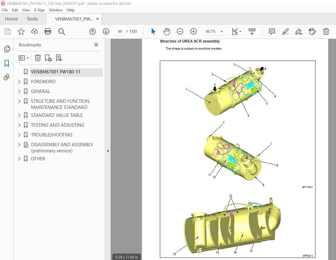
Structure of UREA SCR assembly 69
AdBlue/DEF tank 71
Structure of AdBlue/DEF tank 71
AdBlue/DEF tank sensor 72
Function of AdBlue tank sensor 72
AdBlue/DEF pump 73
AdBlue/DEF injector 74
AdBlue/DEF hose 75
AdBlue/DEF tank heating valve 76
BOOT-UP system 77
Layout drawing of BOOT-UP system 77
System operating lamp system 78
System operating lamp system diagram 78
Function of system operating lamp system 78
Battery disconnect switch 79
Function of battery disconnect switch 79
Engine system 81
Layout drawing of engine system 81
SPECIFICATIONS OF ENGINE SYSTEM 81
Function of engine system 82
Engine control system 82
Engine control system diagram 82
Function of engine control system 83
Auto-deceleration system 86
Auto-deceleration system diagram 86
Engine automatic warm-up system 88
Engine automatic warm-up system diagram 88
Function of engine automatic warm-up system 89
Overheat prevention system 90
Overheat prevention system diagram 90
Function of overheat prevention system 91
Turbocharger protection system 92
Turbocharger protection system diagram 92
Function of turbocharger protection system 93
Automatic idle stop system 93
Automatic idle stop system diagram 93
Function of automatic idle stop system 94
Abrupt engine stop is detected 97
Component parts of engine system 98
Structure of VGT 98
When nozzle ring is “closed” 101
When nozzle ring is “open” 101
Operation of hydraulic actuator 101
EGR system 102
Structure of EGR valve 102
Function of EGR System 102
Circuit Diagram of EGR system 103
OPERATION OF EGR SYSTEM 103
EGR valve 104
Structure of EGR valve 104
Sectional view 104
Structure 105
Operation of EGR valve 105
EGR cooler 106
Structure of EGR cooler 106
General view and sectional view 106
Detailed drawing of flat tube 107
Operation of EGR cooler 107
KCCV system 108
Layout drawing of KCCV system 108
General view 108
Function of KCCV system 109
KCCV ventilator 110
Structure of KCCV ventilator 110
Function of KCCV ventilator 110
Operation of KCCV ventilator 111
CDR valve 111
KDPF 112
Structure of KDPF 112
General view 112
Structure 112
Function of KDPF 114
Types of regeneration functions 116
Cooling system 119
Layout drawing of cooling system 119
Specifications of cooling system 120
Fan speed control system of fan clutch 121
Function of engine output control system of fan clutch 123
At one-touch power maximizing function operation 124
Component parts of cooling system 125
Fan clutch 125
Power train 126
Swing circle 128
Specifications 128
Swing machinery & motor 129
Specification 130
Operation of swing lock 131
Relief valve portion 132
Operation 132
Undercarriage 134
Transmission 136
Specifications 136
Function 138
Second auxiliary circuit control system 139
Trailer coupling for pulling trailers 141
Trailer coupling automatic 141
Trailer coupling ball 141
Disassembly and assembly of trailer hitch on blade 142
Working with blade 143
Inspect trailer hitch 144
Calculation of maximum coupling Load 145
Hydraulic quick coupler 146
Schematic 146
Operation 147
Hydraulic quick coupler solenoid valve 147
Specification 147
Quick coupler error logic 148
Travel motor 152
Function 153
Operation of travel motor 154
Clutch control circuit 156
Function 157
Axle 158
Outline 158
Suspension lock cylinder 161
Specifications 161
Structure and function 161
Circuit 162
Axle oscillation 162
Braking system 163
Structure and function 164
Gear pump 165
Specifications 165
Function 165
Priority valve 167
Specification 167
Function 167
Power brake valve 169
Specifications 170
Function 170
Accumulator for brake valve 171
Specifications 171
Structure and function 171
Steering system 172
Structure and function 172
Joystick steering system 173
Structure and function 174
Steering column JSS 175
Specifications 176
Steering column 178
Orbitrol valve 179
Specifications 179
Structure and function 179
Orbitrol valve JSS 180
Specifications 180
Structure and function 180
Hydraulic equipment layout drawings 181
Hydraulic circuit diagram 183
Hydraulic tank 184
Specifications 184
Hydraulic pump 185
Function 187
Structure 187
Operation 188
LS valve 190
PC valve 191
Function 192
Operation 193
1 LS valve 193
2 PC valve 197
LS(PC)-EPC valve 204
Function 205
Operation 205
Pilot pressure control (PPC) system 208
Function 209
Operation 209
Control main valve 210
Outline 210
CLSS 225
Outline of CLSS 225
Features 225
Structure 225
Basic Principle 226
Operation for each function and valve 228
Hydraulic circuit diagram and name of valves 228
1 Unload valve 230
Function 230
Operation 230
Operation 231
Operation 232
2 Introduction of LS pressure 233
Work equipment valve 233
Function 233
Operation 233
3 LS bypass plug 234
Outline 234
Operation 234
4 Pressure compensation valve 235
Function 235
Operation 236
5 Area ratio of pressure compensation valve 237
Function 237
6 Boom regeneration circuit 238
Function 238
Operation 238
Function 239
Operation 239
7 Arm regeneration circuit 240
Function 240
Operation 240
Function 241
Operation 241
8 Swing bleeding valve 242
Function 242
Operation (In fine control operation) 242
9 Variable type pressure compensation valve (for service) 243
Function 243
Simultaneous operation with work equipment under heavy load (boom RAISE, etc ) 243
10 LS select valve 244
Function 244
Operation 244
Centre swivel joint 245
Travel PPC pedal 246
Work equipment – Swing PPC valve 248
Operation 250
Solenoid valve block with integrated ATT – EPC 252
ATT EPC valve assembly 254
ON / OFF Solenoid valves (3 way valve) 255
Operation 255
ON / OFF Solenoid valves (4 way valve) 257
Operation 257
Hi/ Lo Solenoid valve (4 way valve) 259
Operation 259
Attachment PPC valve 261
Function 262
Operation 262
Bucket to 2ATT 264
Function 264
Activate by switch (RH console of cabin) 265
Boom safety valve 266
Operation 267
Boom floating 268
PPC pressure reduction/ Boom floating logic 268
Hydraulic cylinder 275
Boom cylinder 275
Arm cylinder 275
Bucket cylinder 275
Adjust cylinder 276
Outrigger cylinder 278
Dozer cylinder 280
Function 281
Work equipment 282
Work equipment 283
1 Dimension of arm 284
2 Dimension of bucket 286
Tool control 288
Tool control schematic (detail from hydraulic diagram) 289
ECSS 290
ECSS Logic 290
ESS Hydraulic Schematic 292
ECSS Accumulator position 293
ECSS Valve 294
ECSS Hydraulic diagram 295
ECSS Function 296
ECSS Logic 296
ESS Hydraulic Schematic 298
ECSS Accumulator position 299
ECSS Valve 300
ECSS Hydraulic diagram 301
Breaker return valve 302
Function 302
Air conditioner 306
Air conditioner component 306
Specifications of air conditioner 309
Electrical wiring diagram 310
Electrical system 311
Engine control 311
1 Operation of System 311
2 Component 312
Engine controller 313
Input and output signals of engine controller 313
Pump controller 319
Machine control system diagram 323
1 Engine and pump control function 324
Function 325
Function 329
Function 331
Function 333
Operation 334
Function 335
Function 339
Function 341
Function 344
Specifications 345
Function 345
Function 346
Operation 346
Machine monitor system 349
Function of machine monitor 351
Monitor display 355
Monitor items and display 357
Caution monitor 359
Pilot monitor 363
Monitor switches 367
Declaration of switch function on keypad 368
Guidance icon and function switch 370
Operator mode function of machine monitor 373
Service mode function of machine monitor 375
KOMTRAX system 377
KOMTRAX system diagram 377
KOMTRAX terminal 378
Structure of KOMTRAX terminal 378
Function of KOMTRAX terminal 378
KomVision system 380
Layout drawing of KomVision system 380
Chassis part 380
Around cab and floor 381
KomVision system diagram 381
Function of KomVision system 382
KomVision controller 383
Structure of KomVision controller 383
Structure of KomVision camera 387
Overload warning device 388
Outline 388
Function 388
Structure 388
Sensor 389
Ambient pressure sensor 391
Charge (boost) pressure and temperature sensor 392
Coolant temperature sensor 393
Ne (crankshaft) speed sensor 393
Bkup (camshaft) speed sensor 394
Common rail pressure sensor 394
Exhaust manifold pressure sensor 395
EGR orifice temperature sensor 395
EGR valve lift sensor 396
KVGT speed sensor 397
KVGT position sensor 398
Mass air flow and temperature sensor 399
KDPF differential pressure and outlet pressure sensor 400
KDOC inlet temperature sensor 401
KDOC outlet temperature sensor 401
Crankcase pressure sensor 402
Engine oil level sensor 403
Fuel level sensor 404
WIF (Water-In-Fuel detection) sensor 405
Coolant level sensor 406
Hydraulic oil temperature sensor 407
Air cleaner clogging sensor 407
Overload Caution sensor 408
Swing proximity sensor 409
Brake sensors 409
Brake accumulator low pressure sensor (CN-P60) 410
Brake stop light sensor (CN-S19) 410
Service brake pressure sensor (CN-S40) 410
Service brake pressure sensor (CN-P62) 410
Park brake pressure sensor (CN-P61) 411
PPC pressure sensors 411
DPF-SCR Area 412
Pump pressure sensor 413
PPC levers 414
LH PPC lever 414
RH PPC lever 415
1st attachment circuit hydraulic performance (main valve bypassed) 416
Travel system 417
Travel circuit 417
Travel Motor Performance 418
Auto-grease pump 420
Overview 421
Display and control unit 421
LED-display 422
Push buttons 422
Three-digit LED display 423
Check central lubrication system, fill up grease 424
Lubrication diagrams 425
Auto-grease pump with one-piece boom 425
Auto-grease pump with two-piece boom 426
Manual system one-piece boom 427
Manual system two-piece boom 428
STANDARD VALUE TABLE 429
Standard value table for engine related parts 430
Standard value table for chassis related parts 434
Flow control characteristic of PC valve (STD) 447
PM clinic service 448
Check sheet 449
TESTING AND ADJUSTING 455
Abbreviation list 458
List of abbreviations used in the text 458
List of abbreviations used in the circuit diagrams 462
Engine and cooling system 463
Test engine speed 463
Method for testing engine speed 463
Test boost pressure 466
Method for testing boost pressure on machine monitor 466
Method for testing boost pressure 467
Test exhaust gas colour 468
Method for testing exhaust gas colour by handy smoke checker 468
Hod for testing exhaust gas colour by smoke meter 469
Test and adjust valve clearance 471
Method for testing valve clearance 471
Method for adjusting valve clearance 472
Test compression pressure 473
Method for testing compression pressure 473
Test blow by pressure 478
Method for testing blow by pressure 478
Test engine oil pressure 480
Test EGR valve and KVGT oil pressure 481
Method for testing EGR valve and KVGT oil pressure 481
Handling fuel system parts 483
Releasing residual pressure from fuel system 484
Test fuel pressure 484
Method for testing fuel pressure 486
Testing of low-pressure circuit (fuel main filter inlet side) 486
Testing of low-pressure circuit (pressure difference) 487
Testing of return circuit 488
Testing of negative pressure circuit 489
Test fuel discharge, return and leakage 490
Tools for testing fuel discharge, return and leakage 490
Method for testing fuel discharge, return and leakage 492
Testing supply pump discharge volume 492
Testing supply pump return rate 493
Testing of leakage from pressure limiter 494
Testing the fuel return rate from injector 495
Bleeding air from fuel system 497
Method for bleeding air from fuel system 497
Test fuel circuit for leakage 498
Method for testing fuel circuit for leakage 498
Testing method of fuel circuit for leakage at engine low idle 499
Testing method of fuel circuit for leakage at engine high idle 499
Testing method of fuel circuit for leakage at engine rated speed 500
Handle cylinder cut-out mode operation 501
Handle no-injection cranking operation 501
Test and adjust air conditioner compressor belt tension 502
Method for checking air conditioner compressor belt 502
Method for adjusting air conditioner compressor belt 502
Replacing fan belt 504
Method for replacing fan belt 504
Test cooling fan speed 505
Method for testing cooling fan speed 505
Write ash in soot accumulation correction to engine controller 506
Method for writing ash in soot accumulation correction to engine controller 506
Test SCR related functions 507
Test AdBlue/DEF pump raised pressure 510
Method for testing AdBlue/DEF pump raised pressure 511
Test injection amount from AdBlue/DEF injector 514
Tools for testing of injection amount from AdBlue/ DEF injector 514
Method for testing injection amount from AdBlue/DEF injector 515
Test AdBlue/DEF line heater relay 1 518
Tools for testing AdBlue/DEF line heater relay 1 518
Method for testing AdBlue/DEF line heater relay 1 519
Test AdBlue/DEF line heater relay 2 521
Tools for testing AdBlue/DEF line heater relay 2 521
Method for testing AdBlue/DEF line heater relay 2 522
Test AdBlue/DEF pump heater relay 524
Tools for testing AdBlue/DEF pump heater relay 524
Method for testing AdBlue/ DEF pump heater relay 525
Test AdBlue/DEF tank heater valve 527
Tools for testing AdBlue/DEF tank heater valve 527
Method for testing AdBlue/DEF tank heater valve 528
Test denitration efficiency of SCR 530
Method for testing denitration efficiency of SCR 531
Clean AdBlue/DEF tank 534
Testing tools for cleaning of AdBlue/DEF tank 534
Method for cleaning AdBlue/DEF tank 534
Measurement of clearance in swing circle bearing 538
Inspection and adjustment of hydraulic oil pressure in hydraulic circuit for work equipment, swing and travel 539
Measurement 539
Adjustment 540
Inspection and adjustment of control circuit oil pressure 543
Measurement 543
Procedure for pressure reducing adjustment 544
Inspection and adjustment of pump PC (valve inlet) control oil pressure 545
Measurement 545
Adjustment 547
Inspection and adjustment of pump LS differential pressure 549
Measurement 549
Adjustment 552
Measurement of solenoid valve output pressure 553
Checking Proportional Control PPC Circuit 556
Adjustment of work equipment and swing PPC valve 557
Measuring and adjusting quick coupler control valve output pressure 558
Specification 559
Testing travel motor relief pressure 560
Measuring travel motor relief pressure 560
Testing propshaft speed 561
Measuring rotating speed of propshaft 561
Testing transmission clutch control circuit 562
Description 562
Inspection of locations of hydraulic drift of work equipment 564
Release of remaining pressure in hydraulic circuit 566
Measurement of oil leakage 567
Air bleeding of various parts 570
Inspection procedures for diode 573
Electrical system 575
Set and operate machine monitor 575
Specification 576
Operator mode 579
Service mode 584
Table of self-define monitoring 601
Abnormality record menu 610
Default menu 624
Diagnostic tests menu 639
Adjustment menu 651
KOMTRAX settings menu 659
Method for starting up KOMTRAX terminal 663
Inspection and adjustment of ECSS (ACCU pressure) 669
Maintenance 669
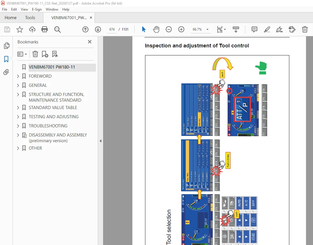
Inspection and adjustment of Tool control 674
Changing the lubrication interval times 680
Changing the Joystick steering control 682
Adjust rearview camera angle 683
Method for adjusting rear view camera angle 683
Adjust KomVision camera angle 686
Tools for adjusting KomVision camera angle 686
Method for adjusting KomVision camera angle 687
Angle adjustment method for front R H camera, rear R H camera, and rear L H camera 687
Angle adjustment method for rear camera 689
Adjust KomVision related items 691
Setting of KomVision (main setting) 691
Method for setting KomVision (main setting) 691
Setting of KomVision (camera setting) 694
Method for setting KomVision (camera setting) 694
Setting of KomVision (camera calibration) 694
Method for setting of KomVision (camera calibration) 695
TROUBLESHOOTING 709
Troubleshooting 709
Troubleshooting by failure code (Display of code) 710
Failure code table (Display of code) 710
Failure code [DB30KR] – Joystick steering controller malfunction 731
Failure code [DA22KK] – Pump solenoid power low error 732
Failure code [DCS2KK] – Machine controller solenoid power voltage low error 734
Failure code [DWB5KY] – Hot short circuit in 4th outrigger solenoid 736
DISASSEMBLY AND ASSEMBLY (preliminary version) 739
FRONT AXLE 739
Note 740
Table of contents 741
Preface 743
General 744
Examples of gear-tooth contact pattern for the Gleason gear-tooth system 746
Conversion table 750
Denomination of standard dimensions 0
Tightening torques for screws 752
Special tools 753
Commercial tools 765
1 Disassembly steering 770
2 Disassembly output 773
2 1 Disassembly planetary carrier 773
2 2 Disassembly brake 774
2 3 Disassembly hub 776
2 4 Disassembly knuckle housing 777
2 5 Disassembly output assy 779
3 Disassembly input 780
4 Disassembly differential 784
4 1 DZ-500 and D-500 784
4 2 DZ-750 and D-750 787
5 Reassembly differential 789
5 1 DZ-500 and D-500 789
5 2 DZ-750 and D-750 793
6 Reassembly input 797
6 1 Install input pinion 797
6 1 1 Determine thickness of the shim to obtain a correct contact pattern 797
6 1 2 Setting of rolling torque of the input pinion bearing 799
6 2 Setting instructions for bevel gear set backlash and bearing rolling torque of the differential bearing 801
6 2 1 Check of backlash pattern of the bevel gear set 803
6 3 Mount shaft seal ring (input flange) 805
7 Reassembly output 806
7 1 Preassembly axle housing 806
7 2 Reassembly knuckle housing 807
7 3 Reassembly hub 811
7 4 Reassembly disk brake 813
7 4 1 Make leakage test of multi-disk brake 816
7 4 2 Adjust and check piston stroke 817
7 5 Reassembly planetary carrier 819
7 6 Reassembly output assy 820
7 7 Reassembly pivot bearing 821
8 Reassembly steering 822
8 1 Preassemble steering 822
8 2 Mount steering 825
8 3 Track setting and checking 827
8 4 Steering angle setting 828
8 5 Check leakage of steering 829
REAR AXLE 830
Note 831
Table of contents 832
Preface 834
General 835
Examples of gear-tooth contact pattern for the Gleason gear-tooth system 837
Conversion table 841
Denomination of standard dimensions 842
Tightening torques for screws 843
Special tools 844
Commercial tools 851
1 Disassembly of output 856
1 1 Disassembly of planetary carrier 856
1 2 Disassembly of brake 857
1 3 Disassembly of hub 859
1 4 Disassembly of output assy 861
2 Disassembly of input 862
2 1 Version with HL transmission 862
2 2 Standard version 864
3 Disassembly differential 867
3 1 DZ-500 und D-500 867
3 2 DZ-750 und D-750 870
4 Reassembly differential 872
4 1 DZ-500 und D-500 872
4 2 DZ-750 und D-750 876
5 Reassembly of input 880
5 1 Version with HL-transmission 880
5 1 1 Determination of shims for setting the bearing rolling torque (differential bearing) and the backlash (bevel gear set) 880
5 2 Standard version (without HL transmission) 885
5 2 1 Reinstallation of input pinion 885
5 2 2 Adjust backlash of crown wheel set and bearing rolling torque of differential bearing 888
5 2 3 Fitting of shaft seal ring (input flange) 892
6 Reassembly of output 893
6 1 Reassembly of hub carrier 893
6 2 Reassembly of hub (Hub bearing SET-RIGHT) 893
6 3 Reassembly of multi-disk brake 896
6 3 1 Leakage test of multi-disk brake 899
6 3 2 Adjustment and check of piston stroke 900
6 4 Reassembly of planetary carrier 901
6 5 Reassembly of output assy 902
TRANSMISSION 903
Note 904
Table of contents 905
Preface 907
General 908
Conversion table 910
Denomination of standard dimensions 911
Torque limits for screws 912
Special tools 913
Commercial tools 922
1 Separate HL-Transmission from axle housing 927
2 Disassembly – Brake/Clutch/Planetary carrier 928
2 1 Lubrication pump and shift interlock 928
2 1 1 Version “Lubrication pump” 928
2 2 Speed sensor 929
2 3 Emergency release (Parking Brake) 929
2 4 Input housing and modulation valve 930
2 5 Brake and clutch 931
2 6 Planetary carrier 937
3 Disassembly – Output 940
3 1 Version “Axle attachment” 940
3 2 Version “Separate Installation” 944
4 Reassembly – Output 947
4 1 Version “Axle attachment” 947
4 1 1 Determine shim for pinion gap 949
4 1 2 Determine adjusting ring for rolling torque/pinion bearing 953
4 1 3 Check rolling torque of pinion bearing 954
4 1 4 Shaft seal output flange 955
4 1 5 Check the pinion gap 956
4 2 Version “Separate installation” 957
4 2 1 Shaft seal output flange 960
5 Reassembly – Brake/Clutch/Planety carrier 963
5 1 Planetary carrier 963
5 2 Brake and clutch 967
5 2 1 Disc components brake and clutch 969
5 2 1 1 Version “HL-290” 969
5 2 1 2 Version “HL-270” 0
5 2 1 3 Version “HL-250” 969
5 2 2 Adjust and check the disc clearance/piston stroke of brake and clutch 971
5 3 Install modulation valve and input housing 978
5 4 Emergency release (Parking brake) 980
5 4 1 Check emergency release for leak tightness 981
5 4 2 Check the multi-disk brake and multi-disc clutch for leak tightness as well as closing pressure 982
5 5 Speed sensor 983
5 6 Lubrication pump/shift interlock 983
6 Disassembly – Lubrication pump/shift interlock and valve block 985
6 1 Version “with” lubrication pump 985
6 2 Version “with” hydr shift interlock 988
6 3 Disassembly valve block 991
7 Reassembly Lubrication pump 993
8 Reassembly shift interlock 999
9 Valve block (shifting low gear – high gear) 1007
10 Mount HL-Transmission to axle 1008
OTHER 1009
Hydraulic circuit diagram 1013
Hydraulic circuit diagram (1/3) 1013
Hydraulic circuit diagram (2/3) 1015
Hydraulic circuit diagram (3/3) 1017
Elektric circuit diagram 1019
Contents 1019
1-0 Power Supply 1021
1-1 Grounding 1022
1-2 Model Select 1023
2-0 Engine PW180 1024
2-1 Engine PW180 1025
2-2 Engine PW148, PW160 1026
2-3 Engine PW148, PW160 1027
2-4 Engine Power Supply, Air Intake 1028
2-5 Engine Start 1029
2-6 2nd ENGINE STOP, OPERATING LAMP 1030
2-7 ADBLUE/DEF DATALINK 1031
2-8 ADDBLUE/DPF POWER 1032
3-0 REFUELING SYSTEM, FUEL DIAL 1033
3-1 BRAKE 1034
3-2 EPC 1035
3-3 CRUISE CONTROL 1036
3-4 TRAVEL 1037
3-5 SUS-LOCK, SPEEDSNR, JOYSTICK POTI 1038
3-6 SENSORS ENGINE & OIL 1039
4-0 QUICK COUPLER, PRESSURE SENSOR 1040
4-1 PPC REDUCTION, FLOATING, PRESSURE SENSOR 1041
4-2 SWING LOCK, PRESSURE SENSOR, JOYSTICK SW 1042
4-3 BUCKET/2ATT SWITCHING 1043
5-0 LOWER ATTACHMENTS 1044
5-1 ROTO-TILT 1045
5-2 BOOM/STABILISER, AUXILARY CIRCUIT, BREAKER 1046
6-0 ROAD LIGHT 1047
6-1 INDICATOR, SIDE LIGHT, STOP LIGHT 1048
6-2 ARM MARKER LIGHT + QC SIGNAL BOOM 1049
6-3 BEACON, TRAILER (OPT) 1050
6-4 WORKLAMP 1051
6-5 WORKLAMP 1052
6-6 CAMERA SW, SERVICE-CON , KOMTRAX, KOMNET 1053
6-7 KOMVISION 1054
7-0 AIR CONDITION, HEATED MIRROR 1055
7-1 RADIO, 12V, CIGAR LIGHTER, ROOM LAMP 1056
7-2 PPC-LOCK, STARTER CUT, SEAT 1057
7-3 ID-KEY 1058
7-4 HORN, ALARM 1059
7-5 WIPER 1060
8-0 CLS 1061
9-0 JOYSTICK STEERING 1062
10-0 FAN CLUTCH, TOOL CONTROL 1063
11-0 ECSS 1064
Harness Summary 1065
Harness Summary 1066
Connector List 1067
Connector List 1068
Connector List 1069
Connector List 1070
Connector List 1071
Connector List 1072
Connector List 1073
Pin Location List 1074
Pin Location List 1075
Pin Location List 1076
Pin Location List 1077
Pin Location List 1078
Pin Location List 1079
Pin Location List 1080
Pin Location List 1081
Pin Location List 1082
Pin Location List 1083
Pin Location List 1084
Pin Location List 1085
Pin Location List 1086
Pin Location List 1087
Pin Location List 1088
Pin Location List 1089
Pin Location List 1090
Pin Location List 1091
Pin Location List 1092
Pin Location List 1093
Pin Location List 1094
Pin Location List 1095
Pin Location List 1096
Pin Location List 1097
Pin Location List 1098
Pin Location List 1099
Pin Location List 1100
Pin Location List 1101
Pin Location List 1102
Pin Location List 1103
Pin Location List 1104
Pin Location List 1105
Pin Location List 1106
Pin Location List 1107
Pin Location List 1108
Pin Location List 1109
Pin Location List 1110
Pin Location List 1111
Pin Location List 1112
Pin Location List 1113
Pin Location List 1114
PARTS LIST 1115
PARTS LIST 1116
PARTS LIST 1117
PARTS LIST 1118
PARTS LIST 1119
Connector diagram 1121
Connector diagram 1/10 1121
Connector table for revolving frame harness 1 1121
Connector diagram 2/10 1122
Connector table for revolving frame harness 2 1122
Connector diagram 3/10 1123
Connector table for operator‘s cab wiring harness (Part 1/2) 1123
Connector diagram 4/10 1124
Connector table for operators cab wiring harness (Part 2/2) 1124
Connector diagram (5/10) 1125
Connector table switch group 1125
Connector diagram (6/10) 1126
Connector table steering 1126
Connector diagram (7/10) 1127
Connector table various wiring harness 1127
Connector diagram (8/10) 1128
Connector table optionally wiring harness (Part 1/3) 1128
Connector diagram (9/10) 1129
Connector table optionally wiring harness (Part 2/3) 1129
Connector diagram (10/10) 1130
DESCRIPTION:
Komatsu PW180-11 Wheeled Excavator Shop Manual VENBM67001 – PDF DOWNLOAD
MACHINE MODEL SERIAL NUMBER
PW180-11 H75051 AND UP
GENERAL PRECAUTIONS :
Mistakes in operation are extremely dangerous. Read the OPERATION & MAINTENANCE MANUAL carefully BEFORE operating the machine.
PREPARATIONS FOR WORK:
PRECAUTIONS DURING WORK :
S.V 30/12/24


