Komatsu PW160-8 Wheeled Excavators Shop Manual VENBM61000 PDF
$35.95
Komatsu PW160-8 Wheeled Excavators Shop Manual VENBM61000 – PDF DOWNLOAD
- PW160-8 H60051 AND UP
Description
Komatsu PW160-8 Wheeled Excavators Shop Manual VENBM61000 – PDF DOWNLOAD
FILE DETAILS:
Komatsu PW160-8 Wheeled Excavators Shop Manual VENBM61000 – PDF DOWNLOAD
Language : English
Pages : 1204
Downloadable : Yes
File Type : PDF
IMAGES PREVIEW OF THE MANUAL:
TABLE OF CONTENTS:
Komatsu PW160-8 Wheeled Excavators Shop Manual VENBM61000 – PDF DOWNLOAD
VENBM61000 PW160-8_ 1
CONTENTS . 3
00 FOREWORD 5
Safety . 5
Important safety notice 5
General precautions 5
Preparations for work 5
Precautions during work 6
General 7
General 7
Structure and function . 7
Testing, adjusting and troubleshooting . 7
Disassembly and assembly . 7
Maintenance standard . 7
How to read the shop manual 8
Volumes 8
Distribution and updating 8
Filing method 8
Revised edition mark . 8
Revisions 8
Symbols 8
Hoisting instructions 9
Hoisting . 9
Wire Ropes . 9
Coating materials 10
Standard tightening torque . 12
Standard tightening torque of bolts and nuts . 12
Tightening torque of hose nuts . 13
Tightening torque of split flange bolts 13
Tightening torques for hoses (taper seal type and face seal type) 13
Tightening torque for 107 engine series (bolts and nuts) . 14
Tightening torque for 107 engine series (eye joints) . 14
Tightening torque for 107 engine series (tapered screws) . 14
Electric wire code . 15
Classification by thickness 15
Classification by color and code . 15
Conversion tables 16
Method of using the conversion table . 16
Units 22
01 GENERAL . 23
Specification dimension drawings . 24
Dimensions . 24
Working ranges . 26
Working range: 1-piece boom 26
Working range: 2-piece boom 27
Specifications . 28
Weight table . 30
1-piece boom . 32
2-piece boom . 33
Fuel, coolant and lubricants . 34
10 STRUCTURE AND FUNCTION, MAINTENANCE STANDARD 35
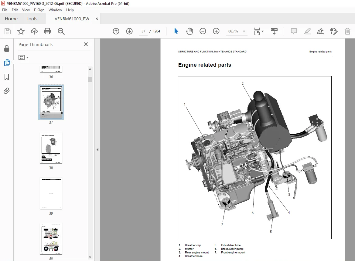
Engine related parts . 37
Radiator • Oil cooler • charge air cooler 38
Power train 40
Swing circle . 42
Specifications . 42
Swing machinery & motor 43
Specification 44
Operation of swing lock 45
Relief valve portion . 46
Operation 46
Undercarriage 48
Transmission . 50
Specifications . 50
Function . 51
Travel motor . 58
Function . 59
Operation of travel motor 60
Clutch control circuit . 62
Function . 63
Axle . 64
Outline 64
Suspension lock cylinder . 69
Specifications . 69
Structure and function . 69
Circuit 70
Axle oscillation . 70
Braking system . 72
Structure and function . 73
Brake/steering pump (except italy) . 74
Specifications . 74
Function . 74
Tandem pump (brake/steering) (for italy) . 75
Specifications . 75
Function . 75
Priority valve . 76
Specification 76
Function . 76
Power brake valve 77
Specifications . 78
Function . 78
Accumulator for brake valve 79
Specifications . 79
Structure and function . 79
Steering system 80
Structure and function . 80
Steering column 81
Orbitrol valve . 82
Specifications . 82
Structure and function . 82
Hydraulic equipment layout drawings 83
Hydraulic circuit diagram 85
Hydraulic tank . 86
Specifications . 86
Hydraulic pump . 87
Function . 89
Structure 89
Operation 90
LS valve . 92
PC valve . 93
Function . 94
Operation 95
1. LS valve 95
2. PC valve 99
LS(PC)-EPC valve . 106
Function . 107
Operation 107
Pilot pressure control (PPC) system 109
Function . 110
Operation 110
Control valve 112
Outline 112
CLSS . 123
Outline of CLSS 123
Features . 123
Structure 123
Basic Principle 124
Operation for each function and valve 126
Hydraulic circuit diagram and name of valves . 126
1. Unload valve 128
Function . 128
Operation 128
Operation 129
Operation 130
2. Introduction of LS pressure . 131
Work equipment valve . 131
Function . 131
Operation 131
3. LS bypass plug 132
Outline 132
Operation 132
4. Pressure compensation valve . 133
Function . 133
Operation 134
5. Area ratio of pressure compensation valve . 135
Function . 135
6. Boom regeneration circuit . 136
Function . 136
Operation 136
Function . 137
Operation 137
7. Arm regeneration circuit 138
Function . 138
Operation 138
Function . 139
Operation 139
8. Swing bleeding valve 140
Function . 140
Operation (In fine control operation) 140
9. Variable type pressure compensation valve (for service) . 141
Function . 141
Simultaneous operation with work equipment under heavy load (boom RAISE, etc.) . 141
10. LS select valve 142
Function . 142
Operation 142
Centre swivel joint 143
Travel PPC pedal . 144
Work equipment – Swing PPC valve . 146
Operation 148
Solenoid valve block . 150
ON / OFF Solenoid valves (3 way valve) . 151
Operation 151
ON / OFF Solenoid valves (4 way valve) . 153
Operation 153
Hi/ Lo Solenoid valve (4 way valve) 155
Operation 155
Attachment PPC valve . 157
Function . 158
Operation 158
Boom safety valve 160
Operation 161
Hydraulic cylinder . 162
Boom cylinder 162
Arm cylinder . 162
Bucket cylinder 162
Adjust cylinder 163
Outrigger cylinder . 164
Dozer cylinder . 166
Function . 167
Work equipment . 168
Work equipment . 169
1. Dimension of arm 170
2. Dimension of bucket . 171
Air conditioner 172
Air conditioner piping . 172
Electrical wiring diagram 173
Electrical system 174
Engine control . 174
1. Operation of System . 174
2. Component . 175
Engine controller 176
Pump controller 178
Electrical control system 181
Machine control system diagram . 182
1. Engine and pump control function 183
Function . 184
Function . 188
Function . 190
Function . 192
Operation 193
Function . 194
Function . 196
Function . 198
Function . 201
Specifications . 202
Function . 202
Function . 203
Operation 203
Machine monitor system . 204
Monitor panel 205
Outline 205
Monitor control, display portion . 208
Monitor gauge displays . 212
Keypad layout 217
Declaration of switch function on keypad . 218
Overload warning device 220
Outline 220
Function . 220
Structure 220
Sensor . 221
Coolant temperature sensor . 222
Oil pressure switch 222
Rotation sensor 223
Boost pressure and temperature sensor 223
WIF (Water-In-Fuel detection) sensor . 224
Engine oil level sensor 224
Coolant level sensor . 225
Coolant temperature sensor . 226
Hydraulic oil temperature sensor . 226
Fuel level sensor 226
Air cleaner clogging sensor 227
Overload Caution sensor 227
Swing proximity sensor . 228
Travel PPC sensor 228
PPC pressure sensor 228
Park brake pressure sensor . 229
Brake accumulator low pressure sensor 229
Brake stop light sensor 229
1st attachment circuit hydraulic performance (main valve bypassed) . 230
Travel system 231
Travel circuit . 231
1. Travel motor 232
2. Travel pedal 241
3. Forward / Neutral / Reverse switch (F-N-R) 242
4. Forward / Reverse travel solenoid . 243
5. Travel / neutral solenoid . 244
6. Travel creep solenoid . 245
Operational and control features . 246
Operational and Control features (1) . 246
Operational and Control features (2) . 246
Operational and Control features (3) . 247
7. 2-Stage relief solenoid . 248
8. Transmission clutch control valve . 250
Steering system 251
Operating principles . 251
Dynamic Steering . 251
2 – stage principle 251
1. Condition 1 . 252
2. Condition 2 . 253
3. Condition 3 . 254
4. Condition 4 . 255
5. Condition 5 . 256
6. Condition 6 . 257
7. OLS priority valve 258
8. Load sensing steering unit 259
Service brake and suspension system 264
Braking system . 264
Operation 267
KOMTRAX terminal system 269
Central lubrication system (CLS) . 271
Auto-grease pump . 271
Overview . 272
Display and control unit . 272
LED-display 273
Push buttons . 273
Three-digit LED display 274
Check central lubrication system, fill up grease . 275
Lubrication diagram 276
Quick coupler control valve 54
Specification 54
Operation 54
Schematic 55
ATT EPC valve assembly . 56
Standard value table for engine related parts 278
Standard value table for chassis related parts . 279
Flow control characteristic of PC valve (STD) 292
PM clinic service 293
Items related to engine 294
Items related to oil pressure 295
Check sheet 296
20 STANDARD VALUE TABLE 277
Checking fuel circuit for leakage 322
Checking and adjusting air conditioner compressor belt tension . 323
Checking . 323
Adjusting 323
Replacing the fan belt . 324
Measurement of clearance in swing circle bearing . 325
Inspection and adjustment of hydraulic oil pressure in hydraulic circuit for work equipment, swing and travel 326
Measurement 326
Adjustment . 327
Inspection and adjustment of control circuit oil pressure 329
Measurement 329
Procedure for pressure reducing adjustment . 330
Inspection and adjustment of pump PC (valve inlet) control oil pressure 331
Measurement 331
Adjustment . 333
Inspection and adjustment of pump LS valve control oil pressure 334
Measurement 334
Adjustment . 337
Measurement of solenoid valve output pressure 338
Measurement of PPC valve output pressure . 343
Checking Proportional Control PPC Circuit 344
Adjustment of work equipment and swing PPC valve . 345
Changing the lubrication interval times 416
30 TESTING AND ADJUSTING . 301
Measuring and adjusting quick coupler control valve output pressure 346
Measuring engine speed . 302
Measuring intake air pressure (boost pressure) . 303
Checking exhaust gas colour 304
Adjusting valve clearance 306
Measurement of compression pressure 308
Measuring blow-by pressure . 310
Measuring engine oil pressure 311
Handling fuel system parts . 312
Releasing residual pressure from fuel system . 313
Measuring fuel pressure 314
Measuring fuel return rate and leakage . 316
Bleeding air from fuel circuit . 320
Solenoid valve block . 340
Testing travel motor relief pressure . 347
Measuring travel motor relief pressure . 347
Adjusting travel motor relief pressure . 348
Testing propshaft speed 349
Measuring rotating speed of propshaft 349
Testing transmission clutch control circuit 350
Description 350
Inspection of locations of hydraulic drift of work equipment . 352
Release of remaining pressure in hydraulic circuit . 354
Measurement of oil leakage . 355
Air bleeding of various parts 358
Inspection procedures for diode 361
Special function of monitor panel 362
40 TROUBLESHOOTING . 417
Troubleshooting 417
Points to remember when troubleshooting 418
Sequence of events in troubleshooting 419
Points to remember when carrying out maintenance . 420
1. Points to remember when handling electric equipment . 420
2. Points to remember when troubleshooting electric circuits . 426
3. Points to remember when handling hydraulic equipment 427
Checks before troubleshooting 429
Classification and steps for troubleshooting . 430
Classification of troubleshooting 430
Steps for troubleshooting 430
Failure-looking phenomenon and troubleshooting no 431
Connector location chart and circuit diagram by system . 439
Connector table 440
Connection table for connector pin numbers . 453
T-boxes and T-adapters table . 481
Before carrying out troubleshooting when failure code is displayed . 488
Information contained in troubleshooting table . 490
Failure code [2G00MA] – Brake oil pressure abnormality . 492
Failure code [6B2JMA] – Travel hydraulic abnormality . 493
Failure code [989L00] – Engine controller lock caution 1 . 493
Failure code [989M00] – Engine controller lock caution 2 . 494
Failure code [989N00] – Engine controller lock caution 3 . 494
Failure code [AA10NX] – Air cleaner clogging . 495
Failure code [AB00KE] – Charge voltage low . 496
Failure code [B@BAZG] – Engine oil pressure low 497
Failure code [B@BAZK] – Engine oil level low . 497
Failure code [B@BCNS] – Engine water overheat 498
Failure code [B@BCZK] – Engine coolant level low . 498
Failure code [B@HANS] – Hydraulic oil overheat . 499
Failure code [CA111] – EMC critical internal failure . 499
Failure code [CA115] – Engine neutral and backup speed sensor error 500
Failure code [CA122] – Charge air press sensor high error 502
Failure code [CA123] – Charge air press sensor low error . 504
Failure code [CA131] – Throttle sensor high error 506
Failure code [CA132] – Throttle sensor low error . 508
Failure code [CA144] – Coolant temperature sensor high error . 510
Failure code [CA145] – Coolant temp sensor low error . 512
Failure code [CA153] – Charge air temperature sensor high error 514
Failure code [CA154] – Charge air temperature sensor low error . 516
Failure code [CA155] – Charge air temperature high speed derate 518
Failure code [CA187] – Sensor supply 2 voltage low error . 520
Failure code [CA221] – Ambient press sensor high error . 522
Failure code [CA222] – Ambient press sensor low error 524
Failure code [CA227] – Sensor supply 2 volt high error . 526
Failure code [CA234] – Engine overspeed 527
Failure code [CA238] – NE speed sensor supply voltage error 528
Failure code [CA271] – IMV/PCV1 short circuit error 529
Failure code [CA272] – IMV/PCV1 open error . 530
Failure code [CA322] – Injector #1 (L#1) open/short circuit error 532
Failure code [CA324] – Injector #3 (L#3) open/short circuit error 534
Failure code [CA331] – Injector #2 (L#2) open/short circuit error 536
Failure code [CA342] – Calibration code incompatibility 540
Failure code [CA351] – Injectors drive circuit error . 542
Failure code [CA352] – Sensor power supply 1 voltage low error . 544
Failure code [CA386] – Sensor power supply 1 voltage high error 546
Failure code [CA428] – Water-in-fuel sensor high error . 548
Failure code [CA429] – Water-in-fuel sensor low error 550
Failure code [CA435] – Engine oil pressure switch error 552
Failure code [CA441] – Battery voltage low error . 553
Failure code [CA442] – Battery voltage high error 556
Failure code [CA449] – Common rail pressure very high error 558
Failure code [CA451] – Common rail pressure sensor high error 560
Failure code [CA452] – Common rail pressure sensor low error . 562
Failure code [CA488] – Charge air temperature high torque derate . 564
Failure code [CA553] – Common rail pressure high error . 564
Failure code [CA559] – Common rail pressure low error 565
Failure code [CA689] – Engine Ne speed sensor error 566
Failure code [CA731] – Engine G speed sensor phase error . 568
Failure code [CA757] – All continuous data lost error 570
Failure code [CA778] – Engine G speed sensor error . 572
Failure code [CA1633] – KOMNET Datalink timeout error 574
Failure code [CA2185] – Throttle sensor supply voltage high error 576
Failure code [CA2186] – Throttle sensor supply voltage low error . 577
Failure code [CA2249] – Common rail pressure very low error 578
Failure code [CA2311] – IMV solenoid error . 580
Failure code [CA2555] – Grid heater relay volt high error 582
Failure code [CA2556] – Grid heater relay volt low error . 584
Failure code [D110KB] – Short circuit in battery relay . 586
Failure code [D19JKZ] – Personal code relay abnormality 588
Failure code [D862KA] – GPS antenna disconnection 590
Failure code [DA22KK] – Pump solenoid power supply voltage low error . 592
Failure code [DA25KP] – Pressure sensor power abnormality 594
Failure code [DA26KP] – 5V sensor 2 power abnormality 596
Failure code [DA29KQ] – Model selection abnormality 598
Failure code [DA2RMC] – CAN disconnection (Pump controller detected 600
Failure code [DAF8KB] – Short circuit in camera power supply . 602
Failure code [DAFGMC] – GPS module operation error . 604
Failure code [DAFRMC] – CAN disconnection (monitor detected 606
Failure code [DDP4KX] – Disconnection in travel PPC pressure switch 608
Failure code [DDWCKZ] – Disconnection in direction control switches 610
Failure code [DFB1KZ] – Service lever potentiometer 1 abnormality 612
Failure code [DFB2KZ] – 2nd ATT service lever main potentio 2 abnormality 614
Failure code [DFB3L8] – RH Lever potentiometer (for 1st ATT) has failure . 616
Failure code [DFB4L8] – 2nd ATT service lever potentio 2 error . 617
Failure code [DFB5KZ] – 1st ATT service lever main potentio 1 abnormality 618
Failure code [DFB6KZ] – Service lever potentiometer 2 abnormality 620
Failure code [DGH2KB] – Hydraulic oil temperature sensor short circuit . 622
Failure code [DH10KS] – Abnormality in 24V sensor power source . 624
Failure code [DHPAMA] – F pump press sensor abnormality 625
Failure code [DHS5KX] – Abnormality in travel PPC sensor . 627
Failure code [DHX1MA] – Overload sensor abnormality (analog) . 629
Failure code [DLT4KA] – Disconnection in transmission speed sensor . 631
Failure code [DW27KA] – Disconnection in transmission clutch solenoid 633
Failure code [DW27KB] – Short circuit in transmission clutch solenoid 635
Failure code [DW4AKA] – Disconnection in suspension lock solenoid 637
Failure code [DW4AKB] – Short circuit in suspension lock solenoid 639
Failure code [DW4CKA] – Disconnection in PPC lock solenoid (S/N H60051 – H60103) . 641
Failure code [DW4CKA] – Disconnection in PPC lock solenoid (S/N H60104 and up) . 643
Failure code [DW4CKB] – PPC lock sol. S/C (S/N H60051 – H60103) 645
Failure code [DW4CKB] – PPC lock sol. S/C (S/N H60104 and up) 647
Failure code [DW4MKA] – Disconnection in creep solenoid 649
Failure code [DW4MKB] – Short circuit in creep solenoid 650
Failure code [DW44KA] – Disconnection in travel F/R solenoid . 651
Failure code [DW44KB] – Short circuit in travel F/R solenoid . 653
Failure code [DW45KA] – Disconnection in swing parking brake solenoid 655
Failure code [DW45KB] – Swing holding brake solenoid short circuit . 657
Failure code [DW91KA] – Disconnection in travel neutral solenoid . 659
Failure code [DW91KB] – Short circuit in travel neutral solenoid . 661
Failure code [DWB1KA] – Disconnection in outrigger operation solenoid 663
Failure code [DWB1KB] – Short circuit in outrigger operation solenoid 665
Failure code [DWB2KA] – Disconnection in 1st outrigger solenoid 667
Failure code [DWB2KB] – Short circuit in 1st outrigger solenoid 669
Failure code [DWB3KA] – Disconnection in 2nd outrigger solenoid 671
Failure code [DWB3KB] – Short circuit in 2nd outrigger solenoid 673
Failure code [DWB4KA] – Disconnection in 3rd outrigger solenoid 675
Failure code [DWB4KB] – Short circuit in 3rd outrigger solenoid 677
Failure code [DWB5KA] – Disconnection in 4th outrigger solenoid 679
Failure code [DWB5KB] – Short circuit in 4th outrigger solenoid 681
Failure code [DWK0KA] – Disconnection in 2-stage relief solenoid . 683
Failure code [DWK0KB] – Short circuit in 2-stage relief solenoid . 684
Failure code [DWK2KA] – Disconnection in 2-stage back pressure solenoid 685
Failure code [DWK2KB] – Short circuit in 2-stage back pressure solenoid 686
Failure code [DXA8KA] – Disconnection in PC-EPC (F) solenoid system 687
Failure code [DXA8KB] – Short circuit in PC-EPC (F) solenoid . 689
Failure code [DXE0KA] – Disconnection in LS-EPC solenoid system 691
Failure code [DXE0KB] – Short circuit in LS-EPC solenoid . 692
Failure code [DXEAKA] – Service Current EPC1 Open Circuit (left hand) 693
Failure code [DXEAKB] – Service current EPC1 solenoid short (left hand) 695
Failure code [DXE7KA] – Service current EPC2 solenoid disconnection (right hand) . 697
Failure code [DXE7KB] – Service current EPC solenoid short (right hand) 699
Failure code [DXE8KA] – Service current EPC solenoid disconnection (left hand) . 701
Failure code [DXE8KB] – Service current EPC3 solenoid short (left hand) 703
Failure code [DXE9KA] – Service current EPC solenoid disconnection (right hand) 705
Failure code [DXE9KB] – Service current EPC solenoid short (right hand) 707
Failure code [DXK3KA] – Travel pedal throttle EPC solenoid open circuit 709
Failure code [DXK3KB] – Travel pedal throttle EPC solenoid short circuit . 710
Failure code [DY20KA] – Wiper working abnormality 712
Failure code [DY20MA] – Wiper parking abnormality 714
Failure code [DY2CKA] – Window washer drive system disconnection . 716
Failure code [DY2CKB] – Washer drive short circuit . 718
Failure code [DY2DKB] – Wiper drive (fwd) short circuit 720
Failure code [DY2EKB] – Wiper drive (rev) short circuit 722
Troubleshooting when failure code is indicated . 485
Failure code [CA332] – Injector #4 (L#4) open/short circuit error 538
Preparations for troubleshooting of electrical system 726
Troubleshooting of electrical system (E-mode) 730
Before carrying out troubleshooting of electrical system . 730
Location of fusible links 732
Location of fuse box and fuse numbers 732
Information contained in troubleshooting table . 733
E-1 When starting switch turned ON, machine monitor displays nothing . 734
E-2 When starting switch turned ON (before starting engine), basic check item lights up 736
E-3 Engine does not start (engine does not rotate) . 738
E-4 Preheater does not operate . 742
E-5 Automatic warm-up system does not operate (in cold season) . 744
E-6 All work equipment, swing and travel mechanism do not move or cannot be locked . 746
E-7 Precaution lights up while engine is running . 748
E-8 Emergency stop item lights up while engine is running 754
E-9 Engine coolant temperature gauge does not indicate normally 756
E-10 Hydraulic oil temperature gauge does not indicate normally 757
E-11 Fuel level gauge does not indicate normally . 760
E-12 Contents of display by machine monitor are different from applicable machine 762
E-13 Machine monitor does not display some items . 762
E-14 Function switch does not work . 762
E-15 Auto-decelerator does not operate normally 763
E-16 Working mode does not change 764
E-17 Travel speed does not change 765
E-18 Alarm buzzer cannot be stopped 766
E-19 Windshield wiper and window washer do not operate . 768
E-20 Power maximising function does not operate normally . 770
E-21 Swing holding brake does not operate normally . 771
E-21 – “Boom/Stabiliser RAISE” is not correctly displayed in monitor function 773
E-22 Travel alarm does not sound or does not stop sounding . 774
E-23 Air conditioner does not operate normally (including air conditioner abnormality record) 776
E-24 When starting switch is turned OFF, service meter is not displayed 787
E-25 Machine monitor cannot be set in service mode . 787
E-26 Monitoring function does not display lever control signal normally 788
E-27 KOMTRAX system does not operate normally 800
Troubleshooting of electrical system (E-Mode) 725
Information in troubleshooting table . 803
12V socket . 804
PPC lock circuit . 806
Brake light circuit 808
Undercarriage attachments – Mode selection . 810
Undercarriage attachments – Mode activation 812
Undercarriage attachments – Front left outrigger . 814
Undercarriage attachments – Front right outrigger 816
Undercarriage attachments – Rear left outrigger 818
Undercarriage attachments – Rear right outrigger . 820
Heated seat does not warm up . 822
Suspension lock 824
Lower wiper does not work (optional fitment) . 826
Work lights (operator cab front left) 828
Work lights (operator cab front right) . 830
Work lights (operator cab rear) 832
Work lights (Boom – left hand) . 834
Work lights (Boom – right hand) 836
Work lights (Revolving frame – left hand) 838
Work lights (Revolving frame – right hand) . 840
Work lights (Counterweight – left hand) 842
Work Lights (Counterweight – right hand) . 844
Work Lights (Oil tank – side mount) 846
Flashing beacon (operator’s cabin mount) . 848
Flashing beacon (Counterweight mount) 850
Flashing beacon (Fuel tank mount) 852
Air seat compressor (option – air suspension seat) . 854
Operator’s cab interior light 856
Cigarette lighter 858
Park brake (not activating) 860
Park brake (displayed symbol) 862
RH PPC Lever clamshell roller switch pushed to the RH position . 864
RH PPC Lever clamshell roller switch pushed to the RH or LH position . 866
Horns 868
Swing lock – Normal operation 870
Swing lock – Emergency operation . 872
Neutral start (engine) . 874
Neutral start (engine) cont’d (A) 876
Neutral start (engine) cont’d (B) 878
Neutral start (engine) cont’d (C) 880
Emergency travel control – Forward . 882
Emergency travel control – Neutral . 884
Emergency travel control – Reverse . 886
Driving lights – Main beam . 888
Driving lights – Main beam flash . 890
Driving lights – Main beam dipped 892
Driving lights – Position lights . 894
Indicators – Right hand 898
Indicators – Left hand . 900
Hazard warning lights 902
Hazard warning lights cont’d (A) . 903
Swing lock proximity switch 906
Troubleshooting of electrical system (Error checking of items without monitor codes) . 801
System chart for hydraulic and mechanical systems 910
Information contained in troubleshooting table . 914
H-1 – All work equipment lacks power, or travel and swing speeds are slow 915
H-2 – Engine speed sharply drops or engine stalls 916
H-3 – No work equipment, travel or swing move 917
H-4 – Abnormal noise is heard from around hydraulic pump . 917
H-5 – Auto-decelerator does not work . 918
H-6 – Fine control mode does not function 918
H-7 – Boom moves slowly or lacks power . 919
H-8 – Arm moves slowly or lacks power 920
H-9 – Bucket moves slowly or lacks power . 921
H-10 – Work equipment does not move in its single operation 921
H-11 – Work equipment hydraulic drift is too fast 922
H-12 – Work equipment has big time lag . 923
H-13 – Other work equipment moves when relieving single circuit 923
H-14 – One-touch power max. switch does not operate 924
H-15 – In compound operation, work equipment with larger load moves slowly . 924
H-16 – In swing + boom RAISE operation, boom moves slowly 924
H-17 – In swing + travel, travel speed drops sharply . 925
H-18 – Travel speed does not switch 926
H-19 – Travel speed does not shift, or it is too slow or fast 927
H-20 – Machine does not swing 928
H-21 – Swing acceleration is poor, or swing speed is slow 929
H-22 – Excessive overrun when stopping swing . 930
H-23 – There is big shock when stopping swing 931
H-24 – There is loud abnormal noise caused when stopping swing . 931
H-25 – Swing natural drift is too big 932
H-26 – Swing speed is faster than specified swing speed 932
Troubleshooting of engine (S-MODE) . 935
Method of using troubleshooting chart 935
S-1 – Starting performance is poor . 938
S-2 – Engine does not start 939
S-3 – Engine does not pick up smoothly . 942
S-4 – Engine stops during operations . 943
S-5 – Engine does not rotate smoothly 944
S-6 – Engine lacks output (or lacks power) . 945
S-7 – Exhaust smoke is black (incomplete combustion) . 946
S-8 – Oil consumption is excessive (or exhaust smoke is blue) 947
S-9 – Oil becomes contaminated quickly . 948
S-10 – Fuel consumption is excessive . 949
S-11 – Oil is in coolant (or coolant spurts back or coolant level goes down) . 950
S-12 – Oil pressure drops 951
S-13 – Oil level rises (Entry of coolant/fuel) . 952
S-14 – Coolant temperature becomes too high (overheating) 953
S-15 – Abnormal noise is made 954
S-16 – Vibration is excessive 955
Troubleshooting of central lubrication system (CLS) 956
Trouble 956
Troubleshooting during grease pump operation . 958
Pump element . 959
Check power supply . 960
Changing the control unit 960
Troubleshooting – grease system faults . 961
Venting of the system 962
Troubleshooting of hydraulic, mechanical and central lubrication system 909
Quick coupler 933
50 DISASSEMBLY AND ASSEMBLY 963
How to read this manual 966
Removal and installation of assemblies . 966
Special tools 966
Removal of parts . 966
Installation of parts 966
Sketches of special tools 966
Coating material lists . 967
Special tools list . 970
Sketches of special tools 972
List of tools 974
Precautions when performing operation 975
Removal and installation of fuel supply pump assembly 977
Removal 977
Installation . 978
Removal and installation of fuel injector assembly . 980
Special tools 980
Removal 980
Installation . 982
Removal and installation of front oil seal . 985
Special tools 985
Removal 985
Installation . 985
Removal and installation of rear oil seal 987
Special tools 987
Removal 987
Installation . 988
Removal and installation of cylinder head assembly . 990
Special tools 990
Removal 990
Installation . 995
Removal and installation of fuel cooler assembly .1000
Removal and installation of combination cooler assembly 1001
Removal 1001
Installation .1003
Removal and installation of engine and hydraulic pump assembly .1004
Special tools 1004
Removal 1004
Installation .1008
Removal and installation of engine hood assembly .1011
Removal 1011
Installation .1011
Removal and installation of travel motor .1013
Removal 1013
Installation .1013
Disassembly and assembly of travel motor assembly 1014
Disassembly 1014
Assembly .1016
Removal and installation of swing motor and swing machinery 1018
Removal 1018
Installation .1019
Removal of swing motor assembly 1020
Removal 1020
Installation .1021
Disassembly and assembly of swing motor and swing machinery 1022
Disassembly 1022
Assembly .1024
Removal and installation of front axle assembly 1028
Removal 1028
Installation .1028
Disassembly and assembly of front axle .1029
Disassembly of steering cylinder .1029
Assembly of steering cylinder 1031
Disassembly of epicyclic reduction gear and brake 1035
Assembly of epicyclic reduction gear and brake .1039
Special tools 1039
Disassembly of joint box .1045
Assembly of joint box 1049
Disassembly of beam trumpet and differential unit 1054
Assembly of beam trumpet and differential unit .1057
Disassembly of pinion group 1063
Assembly of pinion group .1065
Toe-in adjustment 1071
Steering angle adjustment 1072
Removal and installation of rear axle and transmission .1073
Removal 1073
Installation .1074
Disassembly and assembly of rear axle assembly .1075
Special tools 1075
Removal of epicyclic reduction gear and brake 1075
Installation of epicyclic reduction gear and brake .1079
Disassembly of beam trumpet and differential unit 1086
Installation of beam trumpet and differential unit .1090
Disassembly of pinion group 1096
Installation of pinion group .1099
Disassembly and assembly of transmission .1105
Special tools 1105
Removal of travel motor and flange .1105
Installation of travel motor .1107
Removal of transmission box 1109
Installation of transmission box .1117
Removal and installation of propshaft assembly .1128
Removal 1128
Installation .1128
Removal and installation of wheel 1129
Removal 1129
Installation .1129
Removal and installation of suspension lock cylinder assembly 1130
Removal 1130
Installation .1130
Disassembly and assembly of suspension lock cylinders 1131
Change Rod Seal 1131
Removal and installation of outrigger assembly .1132
Removal 1132
Installation .1132
Disassembly and assembly of outriggers .1133
Disassembly 1133
Assembly .1133
Removal and installation of dozer blade assembly .1134
Removal 1134
Installation .1134
Disassembly and assembly of dozer blade 1135
Disassembly 1135
Assembly .1135
Removal and installation of swing circle assembly 1136
Removal 1136
Installation .1136
Removal and installation of revolving frame assembly .1137
Removal 1137
Installation .1139
Removal and installation of centre swivel joint 1140
Removal 1140
Installation .1142
Disassembly and assembly of centre swivel joint 1143
Disassembly 1143
Assembly .1144
Removal and installation of fuel tank assembly .1145
Removal 1145
Installation .1146
Removal and installation of hydraulic tank assembly 1147
Removal 1147
Installation .1149
Removal and installation of control valve assembly .1150
Removal 1150
Installation .1152
Removal and installation of LS separation valve assembly .1153
Removal 1153
Installation .1153
Removal and installation of pressure compensation valve assembly .1154
Removal 1154
Installation .1154
Removal and installation of main relief valve assembly .1155
Removal 1155
Installation .1155
Removal and installation of LS control EPC valve .1156
Removal 1156
Installation .1156
Removal and installation of PC EPC valve assembly 1157
Removal 1157
Installation .1157
Removal and installation of 4-station PPC solenoid valve block assembly 1158
Removal 1158
Installation .1158
Removal and installation of oil seal in hydraulic pump input shaft .1160
Special tools 1160
Removal 1160
Installation .1160
Disassembly and assembly of work equipment PPC valve .1161
Assembly .1161
Disassembly and assembly of hydraulic cylinder .1162
Special tools 1162
Disassembly 1162
Assembly .1164
Removal and installation of 1 piece boom work equipment 1168
Special tools 1168
Removal 1168
Installation .1169
Removal and installation of 2 piece boom work equipment 1170
Special tools 1170
Removal 1170
Installation .1171
Removal and installation of air conditioner unit .1172
Special tools 1172
Removal 1172
Installation .1174
Removal and installation of counterweight 1175
Removal 1175
Installation .1176
Removal and installation of operator cab assembly 1177
Removal 1177
Installation .1178
Removal and installation of monitor assembly .1179
Removal 1179
Installation .1179
Removal and installation of pump controller assembly .1180
Removal 1180
Installation .1180
Removal and installation of engine controller assembly .1181
Removal 1181
Installation .1182
Removal and Installation of KOMTRAX terminal .1183
Removal 1183
Installation .1183
General assembly advice for central lubrication system (CLS) .1184
90 OTHER .1185
Hydraulic circuit diagram (1/3) 1187
Hydraulic circuit diagram (2/3) 1188
Hydraulic circuit diagram (3/3) 1189
Electrical circuit diagram (cabin 1/4) .1190
Electrical circuit diagram (cabin 2/4) .1191
Electrical circuit diagram (cabin 3/4) .1192
Electrical circuit diagram (cabin 4/4) .1193
Electrical circuit diagram (machine 1/4)) 1194
Electrical circuit diagram (machine 2/4)) 1195
Electrical circuit diagram (machine 3/4)) 1196
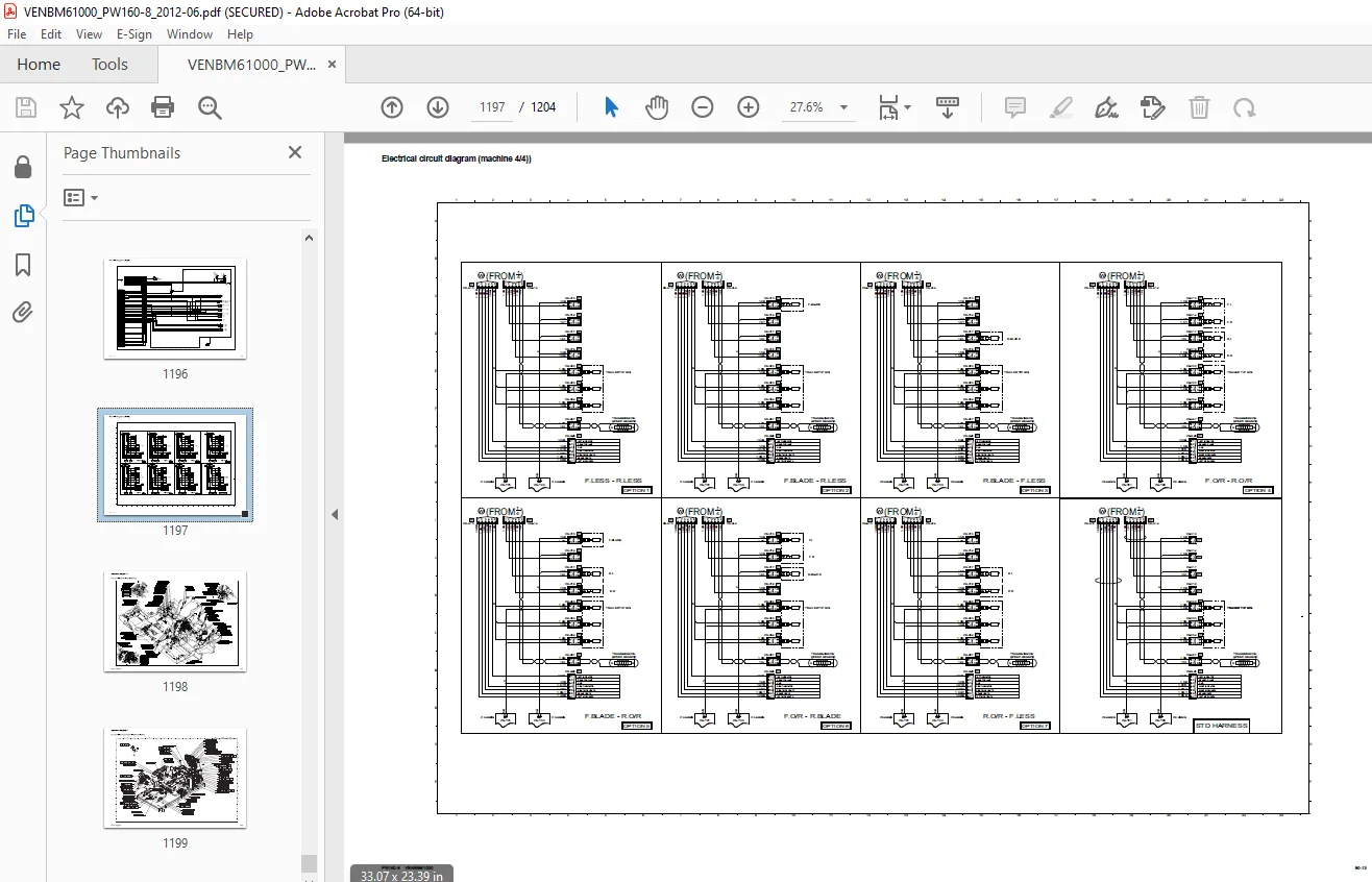
Electrical circuit diagram (machine 4/4)) 1197
Connector diagram 1/7 1198
Connector table for revolving frame harness 1198
Connector diagram 2/7 1199
Connector table for operator‘s cab wiring harness (Part 1/2) .1199
Connector diagram 3/7 1200
Connector table for operators cab wiring harness (Part 2/2) 1200
Connector diagram (4/7) 1201
Connector table various wiring harness (Part 1/3) 1201
Connector diagram (5/7) 1202
Connector table various wiring harness (Part 2/3) 1202
Connector diagram (6/7) 1203
Connector table various wiring harness (Part 3/3) 1203
Connector diagram (7/7) 1204
Connector table optionally wiring harness 1204
DESCRIPTION:
Komatsu PW160-8 Wheeled Excavators Shop Manual VENBM61000 – PDF DOWNLOAD
- PW160-8 H60051 AND UP
General
This shop manual has been prepared as an aid to improve the quality of repairs by giving the serviceman an accurate under- standing of the product and by showing him the correct way to perform repairs and make judgements. Make sure you under- stand the contents of this manual and use it to full effect at every opportunity.
This shop manual mainly contains the necessary technical information for operations performed in a service workshop. For ease of understanding, the manual is divided into the following sections. These sections are further divided into each main group of components.
General
This section lists the general machine dimensions, performance specifications, component weights, and fuel, coolant and lubricant specification charts.
Structure and function
This section explains the structure and function of each component. It serves not only to give an understanding of the structure, but also serves as reference material for troubleshooting.
Testing, adjusting and troubleshooting
This section explains checks to be made before and after per- forming repairs, as well as adjustments to be made at completion of the checks and repairs. Troubleshooting charts correlating “Problems” to “Causes” are also included in this section.
Disassembly and assembly
This section explains the order to be followed when removing. installing, disassembling or assembling each component, as well as precautions to be taken for these operations.
Maintenance standard
This section gives the judgement standards when inspecting dis- assembled parts.
G.B 28/12/24


