Komatsu PW160-11 Wheeled Excavator Shop Manual VENBM69001 PDF
$37.95
Komatsu PW160-11 Wheeled Excavator Shop Manual VENBM69001 – PDF DOWNLOAD
MACHINE MODEL SERIAL NUMBER
PW160-11 H65051 AND UP
Description
Komatsu PW160-11 Wheeled Excavator Shop Manual VENBM69001 – PDF DOWNLOAD
FILE DETAILS:
Komatsu PW160-11 Wheeled Excavator Shop Manual VENBM69001 – PDF DOWNLOAD
Language : English
Pages : 1090
Downloadable : Yes
File Type : PDF
IMAGES PREVIEW OF THE MANUAL:
TABLE OF CONTENTS:
Komatsu PW160-11 Wheeled Excavator Shop Manual VENBM69001 – PDF DOWNLOAD
MACHINE MODEL SERIAL NUMBER
PW160-11 H65051 AND UP
VENBM69001 PW160-11 1
FOREWORD 5
Safety 5
Important safety notice 5
General precautions 5
Preparations for work 5
Precautions during work 6
General 7
General 7
Structure and function 7
Testing, adjusting and troubleshooting 7
Disassembly and assembly 7
Maintenance standard 7
How to read the shop manual 8
Volumes 8
Distribution and updating 8
Filing method 8
Revised edition mark 8
Revisions 8
Symbols 8
Hoisting instructions 9
Hoisting 9
Wire Ropes 9
Coating materials 10
Standard tightening torque 12
Standard tightening torque of bolts and nuts 12
Tightening torque of hose nuts 13
Tightening torque of split flange bolts 13
Tightening torques for hoses (taper seal type and face seal type) 13
Tightening torque for 102,107 and 114 engine series (bolts and nuts) 14
Tightening torque for 102,107 and 114 engine series (eye joints) 14
Tightening torque for 102,107 and 114 engine series (tapered screws) 14
Electric wire code 15
Classification by thickness 15
Classification by color and code 15
Conversion tables 16
Method of using the conversion table 16
Units 22
GENERAL 23
Specification dimension drawings 24
Dimensions 24
Working ranges 26
Working range: 1-piece boom 26
Working range: 2-piece boom 27
Weight table 31
1-piece boom 32
2-piece boom 33
Fuel, coolant and lubricants 34
STRUCTURE AND FUNCTION 37
Abbreviation list 40
List of abbreviations used in the text 40
List of abbreviations used in the circuit diagrams 44
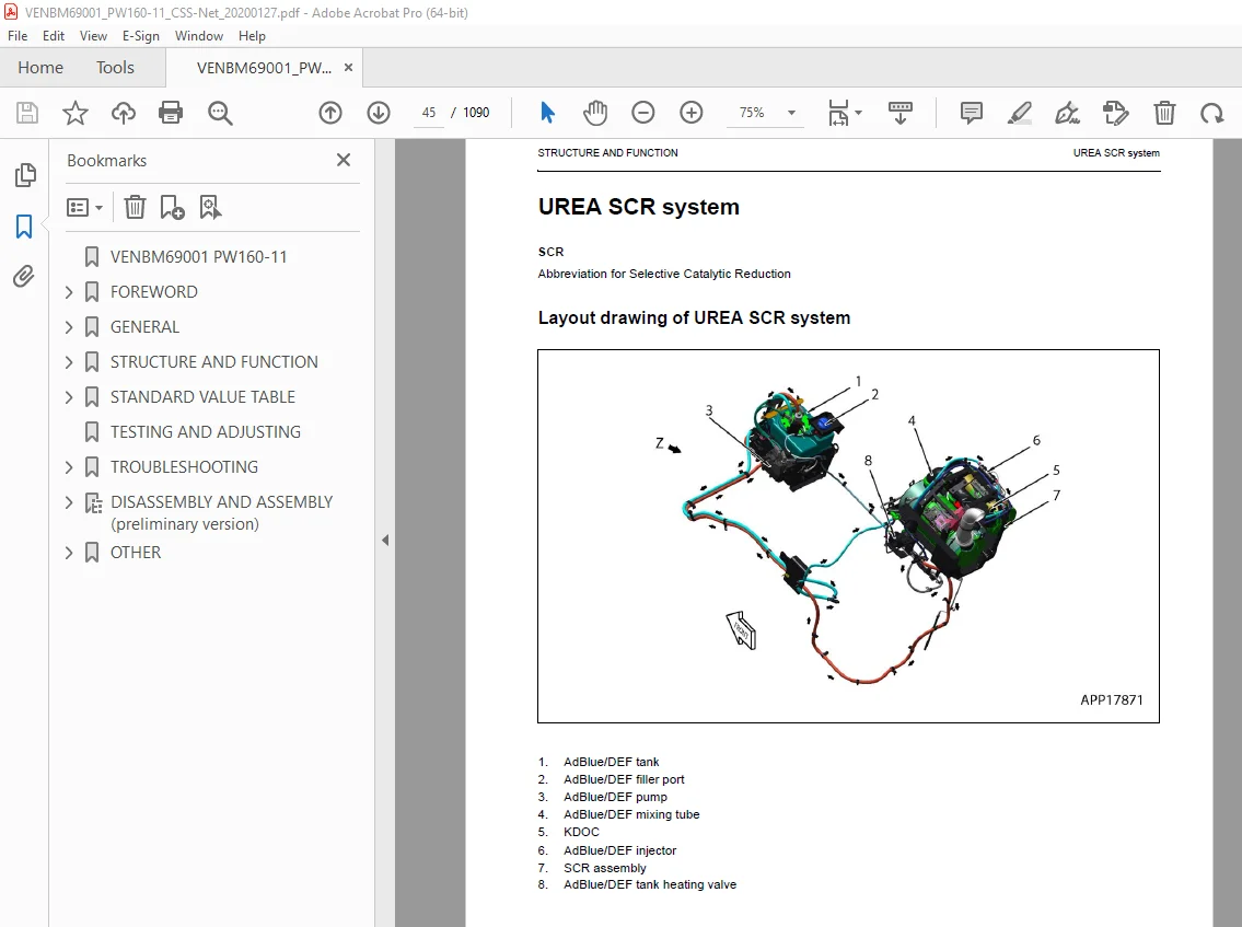
UREA SCR system 45
Layout drawing of UREA SCR system 45
Detailed drawing of SCR assembly 48
Detailed drawing of AdBlue/DEF tank 49
UREA SCR system diagram 50
Function of UREA SCR system 51
Function of AdBlue/DEF system 52
AdBlue/DEF injection function 52
AdBlue/DEF purge function 53
Function of AdBlue/DEF thawing and preventing from freezing 53
Inducement strategy 54
Inducement strategy when the AdBlue/DEF level in the tank becomes low (for north America) 55
Inducement strategy when abnormality is found in the UREA SCR system devices (for north America) 56
Inducement strategy when abnormality is found in the KDOC system by the IREA SCR system (for north America) 58
Function of temporary restoration from inducement (for north America) 60
Inducement strategy for abnormality recurrence within 40 hours (for north America) 61
Inducement strategy when the AdBlue/DEF level in the tank becomes low (for European Union) 62
Inducement strategy when abnormality is found in the AdBlue/DEF quality or in the UREA SCR system devices (for European Union) 64
Inducement strategy when abnormality is found in the KDOC system by the IREA SCR system (for Europan Union) 66
Inducement strategy when abnormality is found in the EGR system by the IREA SCR system devices (foR European Union) 68
Function of temporary restoration from inducement (for European Union) 69
Inducement strategy for abnormality recurrence within 40 hours (for European Union 70
Component parts of UREA SCR system 71
AdBlue/DEF MIXING TUBE 71
SCR assembly 72
Structure of UREA SCR assembly 72
AdBlue/DEF tank 74
Structure of AdBlue/DEF tank 74
AdBlue/DEF tank sensor 75
Function of AdBlue tank sensor 75
AdBlue/DEF pump 76
AdBlue/DEF injector 77
AdBlue/DEF hose 78
AdBlue/DEF tank heating valve 79
BOOT-UP system 80
Layout drawing of BOOT-UP system 80
System operating lamp system 81
System operating lamp system diagram 81
Function of system operating lamp system 81
Battery disconnect switch 82
Function of battery disconnect switch 82
Engine system 84
Layout drawing of engine system 84
Function of engine system 85
Engine control system 85
Engine control system diagram 85
Function of engine control system 86
Auto-deceleration system 89
Auto-deceleration system diagram 89
Engine automatic warm-up system 91
Engine automatic warm-up system diagram 91
Function of engine automatic warm-up system 92
Overheat prevention system 93
Overheat prevention system diagram 93
Function of overheat prevention system 94
Turbocharger protection system 95
Turbocharger protection system diagram 95
Function of turbocharger protection system 96
Automatic idle stop system 97
Automatic idle stop system diagram 97
Function of automatic idle stop system 97
Abrupt engine stop is detected 100
Component parts of engine system 101
Structure of VGT 101
EGR system 104
Layout drawing of EGR system 104
Function of EGR system 104
Circuit diagram of EGR system 105
Operation of EGR system 105
EGR valve 106
Structure of EGR valve 106
General view and sectional view 106
Operation of EGR valve 107
EGR cooler 108
Structure of EGR cooler 108
General view and sectional view 108
Detailed drawing of flat tube 109
Operation of EGR cooler 109
KCCV system 110
Layout drawing of KCCV system 110
KCCV ventilator 112
Structure of KCCV ventilator 112
Function of KCCV ventilator 112
Operation of KCCV ventilator 113
CDR valve 113
KDOC 114
Structure of KDOC 114
Function of KDOC 115
Types of regeneration functions 115
Cooling system 118
Layout drawing of cooling system 118
Specifications of cooling system 119
Fan speed control system of fan clutch 120
Engine output control system of fan clutch 122
Engine output control system diagram of fan clutch 122
Function of engine output control system of fan clutch 123
Component parts of cooling system 124
Fan clutch 124
Power train 126
Swing circle 128
Specifications 128
Swing machinery & motor 129
Specification 130
Operation of swing lock 131
Relief valve portion 132
Operation 132
Undercarriage 134
Transmission 136
Specifications 136
Function 138
Trailer 139
Calculation of maximum coupling Load 139
Automatic trailer coupling for blade 140
Functional check 140
Possible faults in the coupling 141
Wear limits 142
Automatic trailer coupling for outrigger 144
Functional check 144
Height adjustment components 145
Functional check 145
Possible faults in the coupling 146
Wear limits 148
Inspection 150
2nd Auxiliary circuit in the undercarriage 152
Function 152
Specifications 153
Schematic of auxiliary circuit 153
Hydraulic quick coupler 154
Schematic 154
Operation 155
Hydraulic quick coupler solenoid valve 155
Specification 155
Quick coupler error logic 156
Full hydraulic quick coupler 157
Travel motor 160
Function 161
Operation of travel motor 162
Clutch control circuit 164
Function 165
Axle 166
Outline 166
Suspension lock cylinder 170
Specifications 170
Structure and function 170
Circuit 171
Axle oscillation 171
Braking system 172
Structure and function 173
Gear pump 174
Specifications 174
Function 174
Priority valve 176
Specification 176
Function 176
Power brake valve 178
Specifications 179
Function 179
Accumulator for brake valve 180
Specifications 180
Structure and function 180
Steering system 181
Structure and function 181
Joystick steering system 182
Structure and function 183
Steering column JSS 184
Specifications 185
Steering column STD 187
Steering column JSS 188
Orbitrol valve STD 189
Specifications 189
Structure and function 189
Orbitrol valve JSS 190
Specifications 190
Structure and function 190
Hydraulic equipment layout drawings 191
Hydraulic circuit diagram 193
Hydraulic tank 194
Specifications 194
Hydraulic pump 195
Function 197
Structure 197
Operation 198
LS valve 200
PC valve 201
Function 202
Operation 203
1 LS valve 203
2 PC valve 207
LS(PC)-EPC valve 214
Function 215
Operation 215
Pilot pressure control (PPC) system 218
Function 219
Operation 219
Control main valve 220
Outline 220
CLSS 235
Outline of CLSS 235
Features 235
Structure 235
Basic Principle 236
Operation for each function and valve 238
Hydraulic circuit diagram and name of valves 238
1 Unload valve 240
Function 240
Operation 240
Operation 241
Operation 242
2 Introduction of LS pressure 243
Work equipment valve 243
Function 243
Operation 243
3 LS bypass plug 244
Outline 244
Operation 244
4 Pressure compensation valve 245
Function 245
Operation 246
5 Area ratio of pressure compensation valve 247
Function 247
6 Boom regeneration circuit 248
Function 248
Operation 248
Function 249
Operation 249
7 Arm regeneration circuit 250
Function 250
Operation 250
Function 251
Operation 251
8 Swing bleeding valve 252
Function 252
Operation (In fine control operation) 253
9 LS select valve 254
Function 254
Operation 254
Centre swivel joint 255
Travel PPC pedal 256
Work equipment – Swing PPC valve 258
Operation 260
Solenoid valve block with integrated ATT – EPC 262
ATT EPC Assembly 264
ON / OFF Solenoid valves (3 way valve) 265
Operation 265
ON / OFF Solenoid valves (4 way valve) 267
Operation 267
Hi/ Lo Solenoid valve (4 way valve) 269
Attachment PPC valve 270
Function 271
Operation 271
Undercarriage solenoid valve block 273
Boom/Outrigger schematic 274
Undercarriage attachment schematic 275
Proportional attachment control 276
Proportional attachment schematic 277
Bucket to 1ATT 278
Function 278
Bucket to 1 ATT valve 279
Boom safety valve 280
Operation 281
Boom floating 282
PPC pressure reduction/ Boom floating logic 282
Hydraulic cylinder 288
Boom cylinder 288
Arm cylinder 288
Bucket cylinder 288
Adjust cylinder 289
Outrigger cylinder 290
Dozer cylinder 292
Function 293
Work equipment 294
Work equipment 295
1 Dimension of arm 296
2 Dimension of bucket 298
Tool control 300
Tool control schematic (detail from hydraulic diagram) 301
ECSS 302
ECSS Logic 302
ECSS Hydraulic Schematic 304
ECSS Accumulator position 305
ECSS Valve 306
ECSS Hydraulic diagram 307
Breaker return valve 308
Function 308
Air conditioner 312
Air conditioner component 312
Specifications of air conditioner 315
Electrical wiring diagram 316
Electrical system 317
Engine control 317
1 Operation of System 317
2 Component 318
Engine controller 319
Structure of engine controller 319
General view 319
Input and output signals of engine controller 319
Pump controller 324
Machine control system diagram 328
1 Engine and pump control function 329
Function 330
Function 334
Function 336
Function 338
Operation 339
Function 340
Function 344
Function 346
Function 349
Specifications 350
Function 350
Function 351
Operation 351
Machine monitor system 355
Function of machine monitor 357
Monitor display 361
Monitor items and display 363
Caution monitor 365
Pilot monitor 369
Monitor switches 373
Declaration of switch function on keypad 374
Guidance icon and function switch 376
Operator mode function 379
Service mode function of machine monitor 381
KOMTRAX system 383
KOMTRAX terminal 384
Structure of KOMTRAX terminal 384
Function of KOMTRAX terminal 384
KomVision system 386
Layout drawing of KomVision system 386
Chassis part 386
Around cab and floor 387
KomVision system diagram 387
Function of KomVision system 388
KomVision controller 389
Structure of KomVision controller 389
Structure of KomVision camera 393
Overload warning device 394
Outline 394
Function 394
Structure 394
Sensor 395
Ambient pressure sensor 397
Charge (boost) pressure and temperature sensor 398
Coolant temperature sensor 399
Ne (crankshaft) speed sensor 399
Bkup (camshaft) speed sensor 400
Common rail pressure sensor 400
Exhaust manifold pressure sensor 401
EGR orifice temperature sensor 401
Variable flow turbocharger motor (with built-in position sensor) 402
EGR valve (with built-in position sensor) 403
EGR valve lift sensor 404
KVGT speed sensor 405
KVGT position sensor 406
Mass air flow and temperature sensor 407
KDOC inlet temperature sensor 408
KDOC outlet temperature sensor 408
Crankcase pressure sensor 409
Engine oil level sensor 410
Fuel level sensor 411
WIF (Water-In-Fuel detection) sensor 412
Coolant level sensor 413
Hydraulic oil temperature sensor 414
Air cleaner clogging sensor 414
Overload Caution sensor 415
Swing proximity sensor 416
Brake sensors 416
Brake accumulator low pressure sensor (CN-P60) 417
Brake stop light sensor (CN-S19) 417
Service brake pressure sensor (CN-S40) 417
Service brake pressure sensor (CN-P62) 417
Park brake pressure sensor (CN-P61) 418
PPC pressure sensors 418
DPF-SCR Area 419
Main valve sensor 420
PPC levers 421
LH PPC lever 421
RH PPC lever 422
1st attachment circuit hydraulic performance (main valve bypassed) 423
Travel system 424
Travel circuit 424
Travel Motor Performance 425
Auto-grease pump 427
Overview 428
Display and control unit 428
LED-display 429
Push buttons 429
Three-digit LED display 430
Check central lubrication system, fill up grease 431
Lubrication diagrams 432
Auto-grease pump with one-piece boom 432
Auto-grease pump with two-piece boom 433
Manual system one-piece boom 434
Manual system two-piece boom 435
Standard value table for engine related parts 438
Standard value table for chassis related parts 446
Flow control characteristic of PC valve (STD) 459
PM clinic service 460
Check sheet 461
STANDARD VALUE TABLE 437
Engine and cooling system 470
Test engine speed 470
Method for testing engine speed 470
Replacing the fan belt 520
Measurement of clearance in swing circle bearing 521
Inspection and adjustment of hydraulic oil pressure in hydraulic circuit for work equipment, swing and travel 522
Measurement 522
Adjustment 523
Inspection and adjustment of control circuit oil pressure 525
Measurement 525
Procedure for pressure reducing adjustment 526
Inspection and adjustment of pump PC (valve inlet) control oil pressure 527
Measurement 527
Adjustment 529
Inspection and adjustment of pump LS differential pressure 530
Measurement 530
Adjustment 532
Measurement of solenoid valve output pressure 533
Checking Proportional Control PPC Circuit 535
Adjustment of work equipment and swing PPC valve 536
Measuring and adjusting quick coupler control valve output pressure 537
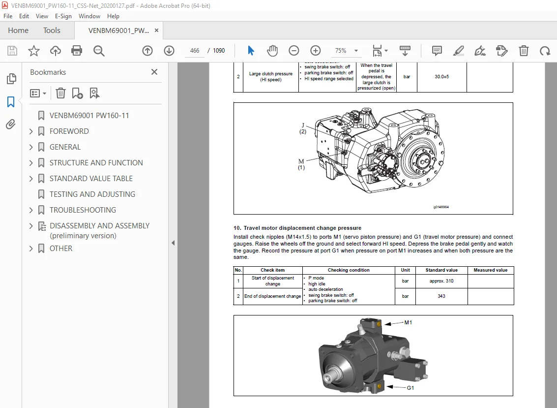
Testing travel motor relief pressure 538
Measuring travel motor relief pressure 538
Testing propshaft speed 539
Measuring rotating speed of propshaft 539
Testing transmission clutch control circuit 540
Description 540
Inspection of locations of hydraulic drift of work equipment 542
Release of remaining pressure in hydraulic circuit 544
Measurement of oil leakage 545
Air bleeding of various parts 548
Inspection procedures for diode 551
Electrical system 552
Special function of monitor panel 552
Service mode 561
Method for checking pre-defined monitoring information 564
Table of self-define monitoring 578
Abnormality record menu 589
Method for confirming maintenance record 594
Method For Operating Maintenance Mode Setting 595
Method for operating phone number entry setting 599
Diagnostic tests menu 612
Adjustment menu 621
KOMTRAX settings menu 629
Method for starting up KOMTRAX terminal 633
Inspection and adjustment of ECSS (ACCU pressure) 638
Maintenance 638
Inspection and adjustment of Tool control 641
Changing the lubrication interval times 647
Adjust rearview camera angle 649
Method for adjusting rear view camera angle 649
Adjust KomVision camera angle 651
Tools for adjusting KomVision camera angle 651
Method for adjusting KomVision camera angle 652
Angle adjustment method for front R H camera, rear R H camera, and rear L H camera 652
Angle adjustment method for rear camera 653
Adjust KomVision related items 655
Setting of KomVision (main setting) 656
Method for setting KomVision (main setting) 656
Setting of KomVision (camera setting) 658
Method for setting KomVision (camera setting) 658
Setting of KomVision (camera calibration) 658
Method for setting of KomVision (camera calibration) 659
TESTING AND ADJUSTING 467
TROUBLESHOOTING 671
Troubleshooting 671
Troubleshooting by failure code (Display of code) 672
Failure code table (Display of code) 672
Failure code [DB30KR] – Joystick steering controller malfunction 691
Failure code [DA22KK] – Pump solenoid power low error 692
Failure code [DCS2KK] – Machine controller solenoid power voltage low error 694
Failure code [DWB5KY] – Hot short circuit in 4th outrigger solenoid 696
General information on troubleshooting 0
Troubleshooting points 0
Sequence of events in troubleshooting 0
1 Points to remember when handling electric equipment 0
2 Points to remember when troubleshooting electric circuits 0
3 Points to remember when handling hydraulic equipment 0
Checks before troubleshooting 0
How to read electric wire code 0
Connector location chart and circuit diagram by system 0
Connector table 0
Connection table for connector pin numbers 0
T-boxes and T-adapters table 0
DISASSEMBLY AND ASSEMBLY (preliminary version) 699
FRONT AXLE 699
Note 700
Table of contents 701
Preface 703
General 704
Examples of gear-tooth contact pattern for the Gleason gear-tooth system 706
Conversion table 710
Denomination of standard dimensions 0
Tightening torques for screws 712
Special tools 713
Commercial tools 725
1 Disassembly steering 730
2 Disassembly output 733
2 1 Disassembly planetary carrier 733
2 2 Disassembly brake 734
2 3 Disassembly hub 736
2 4 Disassembly knuckle housing 737
2 5 Disassembly output assy 739
3 Disassembly input 740
4 Disassembly differential 744
4 1 DZ-500 and D-500 744
4 2 DZ-750 and D-750 747
5 Reassembly differential 749
5 1 DZ-500 and D-500 749
5 2 DZ-750 and D-750 753
6 Reassembly input 757
6 1 Install input pinion 757
6 1 1 Determine thickness of the shim to obtain a correct contact pattern 757
6 1 2 Setting of rolling torque of the input pinion bearing 759
6 2 Setting instructions for bevel gear set backlash and bearing rolling torque of the differential bearing 761
6 2 1 Check of backlash pattern of the bevel gear set 763
6 3 Mount shaft seal ring (input flange) 765
7 Reassembly output 766
7 1 Preassembly axle housing 766
7 2 Reassembly knuckle housing 767
7 3 Reassembly hub 771
7 4 Reassembly disk brake 773
7 4 1 Make leakage test of multi-disk brake 776
7 4 2 Adjust and check piston stroke 777
7 5 Reassembly planetary carrier 779
7 6 Reassembly output assy 780
7 7 Reassembly pivot bearing 781
8 Reassembly steering 782
8 1 Preassemble steering 782
8 2 Mount steering 785
8 3 Track setting and checking 787
8 4 Steering angle setting 788
8 5 Check leakage of steering 789
REAR AXLE 790
Note 791
Table of contents 792
Preface 794
General 795
Examples of gear-tooth contact pattern for the Gleason gear-tooth system 797
Conversion table 801
Denomination of standard dimensions 802
Tightening torques for screws 803
Special tools 804
Commercial tools 811
1 Disassembly of output 816
1 1 Disassembly of planetary carrier 816
1 2 Disassembly of brake 817
1 3 Disassembly of hub 819
1 4 Disassembly of output assy 821
2 Disassembly of input 822
2 1 Version with HL transmission 822
2 2 Standard version 824
3 Disassembly differential 827
3 1 DZ-500 und D-500 827
3 2 DZ-750 und D-750 830
4 Reassembly differential 832
4 1 DZ-500 und D-500 832
4 2 DZ-750 und D-750 836
5 Reassembly of input 840
5 1 Version with HL-transmission 840
5 1 1 Determination of shims for setting the bearing rolling torque (differential bearing) and the backlash (bevel gear set) 840
5 2 Standard version (without HL transmission) 845
5 2 1 Reinstallation of input pinion 845
5 2 2 Adjust backlash of crown wheel set and bearing rolling torque of differential bearing 848
5 2 3 Fitting of shaft seal ring (input flange) 852
6 Reassembly of output 853
6 1 Reassembly of hub carrier 853
6 2 Reassembly of hub (Hub bearing SET-RIGHT) 853
6 3 Reassembly of multi-disk brake 856
6 3 1 Leakage test of multi-disk brake 859
6 3 2 Adjustment and check of piston stroke 860
6 4 Reassembly of planetary carrier 861
6 5 Reassembly of output assy 862
TRANSMISSION 863
Note 864
Table of contents 865
Preface 867
General 868
Conversion table 870
Denomination of standard dimensions 871
Torque limits for screws 872
Special tools 873
Commercial tools 882
1 Separate HL-Transmission from axle housing 887
2 Disassembly – Brake/Clutch/Planetary carrier 888
2 1 Lubrication pump and shift interlock 888
2 1 1 Version “Lubrication pump” 888
2 2 Speed sensor 889
2 3 Emergency release (Parking Brake) 889
2 4 Input housing and modulation valve 890
2 5 Brake and clutch 891
2 6 Planetary carrier 897
3 Disassembly – Output 900
3 1 Version “Axle attachment” 900
3 2 Version “Separate Installation” 904
4 Reassembly – Output 907
4 1 Version “Axle attachment” 907
4 1 1 Determine shim for pinion gap 909
4 1 2 Determine adjusting ring for rolling torque/pinion bearing 913
4 1 3 Check rolling torque of pinion bearing 914
4 1 4 Shaft seal output flange 915
4 1 5 Check the pinion gap 916
4 2 Version “Separate installation” 917
4 2 1 Shaft seal output flange 920
5 Reassembly – Brake/Clutch/Planety carrier 923
5 1 Planetary carrier 923
5 2 Brake and clutch 927
5 2 1 Disc components brake and clutch 929
5 2 1 1 Version “HL-290” 929
5 2 1 2 Version “HL-270” 0
5 2 1 3 Version “HL-250” 929
5 2 2 Adjust and check the disc clearance/piston stroke of brake and clutch 931
5 3 Install modulation valve and input housing 938
5 4 Emergency release (Parking brake) 940
5 4 1 Check emergency release for leak tightness 941
5 4 2 Check the multi-disk brake and multi-disc clutch for leak tightness as well as closing pressure 942
5 5 Speed sensor 943
5 6 Lubrication pump/shift interlock 943
6 Disassembly – Lubrication pump/shift interlock and valve block 945
6 1 Version “with” lubrication pump 945
6 2 Version “with” hydr shift interlock 948
6 3 Disassembly valve block 951
7 Reassembly Lubrication pump 953
8 Reassembly shift interlock 959
9 Valve block (shifting low gear – high gear) 967
10 Mount HL-Transmission to axle 968
OTHER 969
Hydraulic circuit diagram (1/3) 973
Hydraulic circuit diagram (2/3) 975
Hydraulic circuit diagram (3/3) 977
Contents 979
Contents 980
1-0 Power Supply 981
1-1 Grounding 982
1-2 Model Select 983
2-0 Engine PW180 984
2-1 Engine PW180 985
2-2 Engine PW148, PW160 986
2-3 Engine PW148, PW160 987
2-4 Engine Power Supply, Air Intake 988
2-5 Engine Start 989
2-6 2nd ENGINE STOP, OPERATING LAMP 990
2-7 ADBLUE/DEF DATALINK 991
2-8 ADDBLUE/DPF POWER 992
3-0 REFUELING SYSTEM, FUEL DIAL 993
3-1 BRAKE 994
3-2 EPC 995
3-3 CRUISE CONTROL 996
3-4 TRAVEL 997
3-5 SUS-LOCK, SPEEDSNR, JOYSTICK POTI 998
3-6 SENSORS ENGINE & OIL 999
4-0 QUICK COUPLER, PRESSURE SENSOR 1000
4-1 PPC REDUCTION, FLOATING ,PRESSURE SENSOR 1001
4-2 SWING LOCK, PRESSURE SENSOR, JOYSTICK SW 1002
4-3 BUCKET/2ATT SWITCHING 1003
5-0 LOWER ATTACHMENTS 1004
5-1 ROTO-TILT 1005
5-2 BOOM/STABILISER, AUXILARY CIRCUIT, BREAKER 1006
6-0 ROAD LIGHT 1007
6-1 INDICATOR, SIDE LIGHT, STOP LIGHT 1008
6-2 ARM MARKER LIGHT + QC SIGNAL BOOM 1009
6-3 BEACON, TRAILER (OPT) 1010
6-4 WORKLAMP 1011
6-5 WORKLAMP 1012
6-6 CAMERA SW, SERVICE-CON , KOMTRAX, KOMNET 1013
6-7 KOMVISION 1014
7-0 AIR CONDITION, HEATED MIRROR 1015
7-1 RADIO, 12V, CIGAR LIGHTER, ROOM LAMP 1016
7-2 PPC-LOCK, STARTER CUT, SEAT 1017
7-3 ID-KEY 1018
7-4 HORN, TRAVEL ALARM 1019
7-5 WIPER 1020
8-0 CLS 1021
9-0 JOYSTICK STEERING 1022
10-0 FAN CLUTCH, TOOL CONTROL 1023
11-0 ECSS 1024
Harness Summary 1025
Harness Summary 1026
Connector List 1027
Connector List 1028
Connector List 1029
Connector List 1030
Connector List 1031
Connector List 1032
Connector List 1033
Pin Location List 1034
Pin Location List 1035
Pin Location List 1036
Pin Location List 1037
Pin Location List 1038
Pin Location List 1039
Pin Location List 1040
Pin Location List 1041
Pin Location List 1042
Pin Location List 1043
Pin Location List 1044
Pin Location List 1045
Pin Location List 1046
Pin Location List 1047
Pin Location List 1048
Pin Location List 1049
Pin Location List 1050
Pin Location List 1051
Pin Location List 1052
Pin Location List 1053
Pin Location List 1054
Pin Location List 1055
Pin Location List 1056
Pin Location List 1057
Pin Location List 1058
Pin Location List 1059
Pin Location List 1060
Pin Location List 1061
Pin Location List 1062
Pin Location List 1063
Pin Location List 1064
Pin Location List 1065
Pin Location List 1066
Pin Location List 1067
Pin Location List 1068
Pin Location List 1069
Pin Location List 1070
Pin Location List 1071
Pin Location List 1072
Pin Location List 1073
Pin Location List 1074
PARTS LIST 1075
PARTS LIST 1076
PARTS LIST 1077
PARTS LIST 1078
PARTS LIST 1079
Connector diagram 1/10 1081
Connector table for revolving frame harness 1 1081
Connector diagram 2/10 1082
Connector table for revolving frame harness 2 1082
Connector diagram 3/10 1083
Connector table for operator‘s cab wiring harness (Part 1/2) 1083
Connector diagram 4/10 1084
Connector table for operators cab wiring harness (Part 2/2) 1084
Connector diagram (5/10) 1085
Connector table switch group 1085
Connector diagram (6/10) 1086
Connector table steering 1086
Connector diagram (7/10) 1087
Connector table various wiring harness 1087
Connector diagram (8/10) 1088
Connector table optionally wiring harness (Part 1/3) 1088
Connector diagram (9/10) 1089
Connector table optionally wiring harness (Part 2/3) 1089
Connector diagram (10/10) 1090
DESCRIPTION:
Komatsu PW160-11 Wheeled Excavator Shop Manual VENBM69001 – PDF DOWNLOAD
MACHINE MODEL SERIAL NUMBER
PW160-11 H65051 AND UP
GENERAL PRECAUTIONS :
Mistakes in operation are extremely dangerous. Read the OPERATION & MAINTENANCE MANUAL carefully BEFORE operating the machine.
PREPARATIONS FOR WORK:
PRECAUTIONS DURING WORK :
S.V 30/12/24


