Komatsu PC700LC-8E0 Hydraulic Excavator Shop Manual PDF
$38.95
Komatsu PC700LC-8E0 Hydraulic Excavator Shop Manual UENBM00380 – PDF DOWNLOAD
SERIAL NUMBERS PC700LC-8E0 K50001 and up
Description
Komatsu PC700LC-8E0 Hydraulic Excavator Shop Manual UENBM00380 – PDF DOWNLOAD
FILE DETAILS:
Komatsu PC700LC-8E0 Hydraulic Excavator Shop Manual UENBM00380 – PDF DOWNLOAD
Language : English
Pages : 1250
Downloadable : Yes
File Type : PDF
IMAGES PREVIEW OF THE MANUAL:
TABLE OF CONTENTS:
Komatsu PC700LC-8E0 Hydraulic Excavator Shop Manual UENBM00380 – PDF DOWNLOAD
SERIAL NUMBERS PC700LC-8E0 K50001 and up
Shop Manual 1
00 Index and foreword 3
Table of Contents 4
Foreword and general information 14
Safety notice 14
How to read the shop manual 19
Explanation of terms for maintenance standard 21
Handling of hydraulic components 23
Method of disconnecting and connecting push-pull type coupler 25
Handling of electric equipment 28
How to read electric wire code 38
Precautions when performing work 41
Standard tightening torque table 44
List of abbreviation 48
Conversion table 52
01 Specification 57
Contents 58
Specifications 60
Specifications drawing 60
Working range drawings 61
Specifications 62
Table of weight 64
Table of fuel, coolant and lubricants 66
10 Structure and function 67
Contents 68
Engine and cooling system 69
Engine related parts 69
PTO 70
Cooling system 71
Power train system 72
Power train 72
Swing circle 74
Swing machinery 76
Final Drive 78
Undercarriage and frame 79
Track frame and idler cushion 79
Hydraulic system 80
Hydraulic component layout 80
Valve control 82
Hydraulic tank and filter 84
Hydraulic pump (piston pump) 86
Cooling fan pump 114
Cooling fan motor 122
Control valve 128
Swing motor 144
Travel motor 152
PPC valve 163
Solenoid valve 171
PPC shuttle valve 178
Boom drift prevention valve 179
Boom LOWER regeneration valve 183
Arm regeneration valve 186
Hydraulic drift prevention valve 189
Quick return valve 194
Line oil filter 197
Centre swivel joint 198
Accumulator 199
Electrical system 200
Engine control 200
Electrical control system 209
Monitor system 239
KOMTRAX system 265
Sensors 267
20 Standard value table 271
Contents 272
Standard value table 273
Standard value table for engine 273
Standard value table for machine 274
30 Testing and adjusting 285
Contents 286
Tool for testing, adjusting and troubleshooting 287
Tools for testing, adjusting, and troubleshooting 287
Engine and cooling system 291
Testing engine speed 291
Testing intake air pressure (boost pressure) 293
Testing exhaust gas temperature 294
Testing exhaust gas color 295
Testing and adjusting valve clearance 296
Testing compression pressure 297
Testing blowby pressure 299
Testing engine oil pressure 300
Testing EGR valve and bypass valve drive pressure 301
Handling fuel system parts 302
Releasing remaining pressure from fuel system 303
Testing fuel pressure 304
Cylinder cut-out test mode 305
No-injection cranking 306
Testing fuel return rate and leakage 307
Bleeding air from fuel circuit 310
Testing fuel circuit for leakage 312
Testing and adjusting alternator belt tension 313
Testing and adjusting air conditioner compressor belt tension 314
Undercarriage and frame 315
Testing swing circle bearing clearance 315
Checking and adjusting track tension 316
Hydraulic system 317
Testing and adjusting oil pressure in work equipment, swing and travel circuits 317
Testing and adjusting control circuit oil pressure 322
Testing and adjusting control oil pressure of piston pump 324
Testing servo piston movement 330
Testing PPC valve output pressure 332
Testing output pressure of solenoid valve and PPC shuttle valve 336
Adjusting play of work equipment and swing PPC vavles 342
Isolating the parts causing hydraulic drift in work equipment 343
Testing and adjusting travel deviation 344
Testing fan speed 346
Testing fan circuit oil pressure 347
Releasing remaining pressure from hydraulic circuit 348
Testing oil leakage 349
Bleeding air from each part 353
Electrical system 356
Special functions of machine monitor 356
Handling of voltage circuit of engine controller 400
Preparatory work for troubleshooting of electrical system 401
Inspection procedure of diode 406
Pm clinic 407
Pm Clinic service 407
UNDERCARRIAGE INSPECTION REPORT 418
40 Troubleshooting 419
Contents 420
General information on troubleshooting 426
Points to remember when troubleshooting 426
Sequence of events in troubleshooting 427
Checks before troubleshooting 428
Classification and procedures for troubleshooting 452
Failure codes table 455
Symptom and troubleshooting numbers 459
Information in troubleshooting table 462
Troubleshooting method for open circuit in wiring harness of pressure sensor system 464
Connector list and layout 466
Connection table for connector pin numbers 476
T- branch box and T- branch adapter table 512
Fuse locations 515
Troubleshooting by failure code 518
Failure code [989L00] Engine Controller Lock Caution 1 518
Failure code [989M00] Engine Controller Lock Caution 2 519
Failure code [989N00] Engine Controller Lock Caution 3 520
Failure code [AA10NX] Air Cleaner Clogging 521
Failure code [AB00KE] Charge Voltage Low 522
Failure code [B@BAZG] Eng Oil Press Low 524
Failure code [B@BAZK] Eng Oil Level Low 525
Failure code [B@BCNS] Eng Water Overheat 526
Failure code [B@BCZK] Eng Water Level Low 528
Failure code [B@HANS] Hyd Oil Overheat 530
Failure code [CA111] ECM Critical Internal Failure 532
Failure code [CA115] Eng Ne and Bkup Speed Sens Error 534
Failure code [CA122] Chg Air Press Sensor High Error 536
Failure code [CA123] Chg Air Press Sensor Low Error 538
Failure code [CA131] Throttle Sensor High Error 540
Failure code [CA132] Throttle Sensor Low Error 542
Failure code [CA135] Eng Oil Press Sensor High Error 544
Failure code [CA141] Eng Oil Press Sensor Low Error 546
Failure code [CA144] Coolant Temp Sens High Error 548
Failure code [CA145] Coolant Temp Sens Low Error 550
Failure code [CA153] Chg Air Temp Sensor High Error 552
Failure code [CA154] Chg Air Temp Sensor Low Error 554
Failure code [CA187] Sens Supply 2 Volt Low Error 556
Failure code [CA221] Ambient Press Sens High Error 558
Failure code [CA222] Ambient Press Sens Low Error 560
Failure code [CA227] Sens Supply 2 Volt High Error 562
Failure code [CA234] Eng Overspeed 563
Failure code [CA238] Ne Speed Sens Supply Volt Error 564
Failure code [CA263] Fuel Temp Sensor High Error 566
Failure code [CA265] Fuel Temp Sensor Low Error 568
Failure code [CA271] IMV/PCV1 Short Error 570
Failure code [CA272] IMV/PCV1 Open Error 571
Failure code [CA273] PCV2 Short Error 572
Failure code [CA274] PCV2 Open Error 573
Failure code [CA322] Inj #1(L#1) Open/Short Error 574
Failure code [CA323] Inj #5 (L#5) Open/Short Error 576
Failure code [CA324] Inj #3(L#3) Open/Short Error 578
Failure code [CA325] Inj #6 (L#6) Open/Short Error 580
Failure code [CA331] Inj #2(L#2) Open/Short Error 582
Failure code [CA332] Inj #4 (L#4) Open/Short Error 584
Failure code [CA342] Calibration Code Incompatibility 586
Failure code [CA351] Injectors Drive Circuit Error 587
Failure code [CA352] Sens Supply 1 Volt Low Error 588
Failure code [CA386] Sens Supply 1 Volt High Error 590
Failure code [CA441] Battery Voltage Low Error 590
Failure code [CA442] Battery Voltage High Error 591
Failure code [CA449] Rail Press Very High Error 591
Failure code [CA451] Rail Press Sensor High Error 592
Failure code [CA452] Rail Press Sensor Low Error 594
Failure code [CA553] Rail Press High Error 596
Failure code [CA554] Rail Press Sensor In Range Error 596
Failure code [CA559] Supply Pump Press Low Error 1 597
Failure code [CA689] Eng Ne Speed Sensor Error 600
Failure code [CA731] Eng Bkup Speed Sens Phase Error 602
Failure code [CA757] All Continuous Data Lost Error 603
Failure code [CA778] Eng Bkup Speed Sensor Error 604
Failure code [CA1228] EGR Valve Servo Error 1 606
Failure code [CA1625] EGR Valve Servo Error 2 607
Failure code [CA1626] BP Valve Sol Current High Error 608
Failure code [CA1627] BP Valve Sol Current Low Error 610
Failure code [CA1628] Bypass Valve Servo Error 1 612
Failure code [CA1629] Bypass Valve Servo Error 2 613
Failure code [CA1631] BP Valve Pos Sens High Error 614
Failure code [CA1632] BP Valve Pos Sens Low Error 616
Failure code [CA1633] KOMNET Datalink Timeout Error 618
Failure code [CA2185] Throt Sens Sup Volt High Error 620
Failure code [CA2186] Throt Sens Sup Volt Low Error 622
Failure code [CA2249] Rail Press Very Low Error 623
Failure code [CA2271] EGR Valve Pos Sens High Error 624
Failure code [CA2272] EGR Valve Pos Sens Low Error 626
Failure code [CA2351] EGR Valve Sol Current High Error 628
Failure code [CA2352] EGR Valve Sol Current Low Error 630
Failure code [CA2555] Grid Htr Relay Open Circuit Error 632
Failure code [CA2556] Grid Htr Relay Short Circuit Error 634
Failure code [D110KB] Battery Relay Drive Short Circuit 636
Failure code [D163KB] Flash Light Relay Short Circuit 638
Failure code [D195KA] Step Light Relay Open Circuit 640
Failure code [D195KB] Step Light Relay Short Circuit 642
Failure code [D19JKZ] Personal code relay abnormality 644
Failure code [D862KA] GPS Antenna Open Circuit 646
Failure code [DA22KK] Pump Solenoid Power Low Error 648
Failure code [DA25KP] 5V Sensor1 Power Abnormality 650
Failure code [DA29KQ] Model Selection Abnormality 652
Failure code [DA2RMC] CAN Discon (Pump Con Detected) 654
Failure code [DA80MA] Auto Lub Abnormal 658
Failure code [DAF8KB] Camera Power Supply Short Circuit 660
Failure code [DAFGMC] GPS Module Error 662
Failure code [DAFRMC] CAN Discon (Monitor Detected) 663
Failure code [DGE5KB] Ambi Temp Sensor Short Circuit 668
Failure code [DGH2KB] Hyd Oil Sensor Short 670
Failure code [DHPAMA] F Pump Press Sensor Abnormality 672
Failure code [DHPBMA] R Pump Press Sensor Abnormality 674
Failure code [DV20KB] Travel alarm short circuit 676
Failure code [DW43KA] Travel Speed Sol Open Circuit 678
Failure code [DW43KB] Travel Speed Sol Short Circuit 680
Failure code [DW45KA] Swing Brake Sol Open Circuit 682
Failure code [DW45KB] Swing Brake Sol Short Circuit 684
Failure code [DW48KA] CO Cancel Sol Open Circuit 686
Failure code [DW48KB] CO Cancel Sol Short Circuit 688
Failure code [DW4XKA] Bucket Curl Hi Cancel Sol Open Circuit 690
Failure code [DW4XKB] Bucket Curl Hi Cancel Sol Short Circuit 692
Failure code [DW7BKA] Fan Reverse Sol Open Circuit 694
Failure code [DW7BKB] Fan Reverse Sol Short Circuit 696
Failure code [DWK0KA] 2-stage Relief Sol Open Circuit 698
Failure code [DWK0KB] 2-stage Relief Sol Short Circuit 700
Failure code [DX16KA] Fan Pump EPC Sol Open Circuit 702
Failure code [DX16KB] Fan Pump EPC Sol Short Circuit 703
Failure code [DXA0KA] TVC Sol Open Circuit 704
Failure code [DXA0KB] TVC Sol Short Circuit 706
Failure code [DY20KA] Wiper Working Abnormality 708
Failure code [DY20MA] Wiper Parking Abnormality 712
Failure code [DY2CKA] Washer Drive Open Circuit 714
Failure code [DY2CKB] Washer Drive Short Circuit 716
Failure code [DY2DKB] Wiper Drive (Fwd) Short Circuit 718
Failure code [DY2EKB] Wiper Drive (Rev) Short Circuit 722
Failure code [DY2FMA] Upper Wiper Working Abnormality 726
Failure code [DY2GKM] Wiper Select Abnormality 728
Troubleshooting of electrical system (E-mode) 732
E-1 Engine does not start (Engine does not crank) 732
E-2 Preheater does not operate 737
E-3 When starting switch is turned to ON position, machine monitor displays nothing 741
E-4 When starting switch is turned to ON position (before starting engine), basic check monitor lights up 744
E-5 Precaution item lights up while engine is running 746
E-6 Emergency stop item lights up while engine is running 748
E-7 Engine coolant temperature gauge does not indicate properly 749
E-8 Fuel gauge does not indicate properly 750
E-9 Hydraulic oil temperature gauge does not indicate properly 752
E-10 Content of display on machine monitor is different from that of actual machine 754
E-11 Some areas of machine monitor screen are not displayed 754
E-12 Function switch does not operate 754
E-13 Automatic warm-up system does not operate (in cold season) 755
E-14 Auto-decelerator does not operate properly 756
E-15 Working mode does not change 757
E-16 Travel speed does not change 758
E-17 Alarm buzzer cannot be cancelled 759
E-18 When starting switch is turned OFF, service meter is not displayed 759
E-19 Service mode cannot be selected 759
E-20 Any of work equipment, swing and travel does not work or cannot be locked 760
E-21 Machine push-up function does not work or cannot be cancelled 762
E-22 Boom shockless function does not operate normally 764
E-23 Swing brake does not operate normally 766
E-24 Windshield wiper and window washer do not operate 768
E-25 Travel alarm does not sound or does not stop sounding 771
E-26 BOOM RAISE indicator is not displayed properly with monitoring function 772
E-27 BOOM LOWER indicator is not displayed properly with monitoring function 774
E-28 ARM IN indicator is not displayed properly with monitoring function 776
E-29 ARM DUMP indicator is not displayed properly with monitoring function 778
E-30 BUCKET CURL indicator is not displayed properly with monitoring function 780
E-31 BUCKET DUMP indicator is not displayed properly with monitoring function 782
E-32 Swing indicator is not displayed properly with monitoring function 784
E-33 Travel indicator is not displayed properly with monitoring function 786
E-34 “Service” is not displayed normally by monitoring function 788
E-35 Electric grease gun does not operate 790
E-36 KOMTRAX system does not operate normally 791
E-37 Bottom dump does not operate properly 792
E-38 Horn does not sound or does not stop sounding 795
E-39 Step light does not light up or go off 798
Troubleshooting of hydraulic and mechanical system (H-mode) 802
Before troubleshooting for hydraulic and mechanical systems 802
Information in troubleshooting table (H-mode) 807
H-1 All of work equipment, travel and swing work slow or lack power 808
H-2 Engine speed lowers significantly or engine stalls 810
H-3 Any of work equipment, swing and travel does not work 812
H-4 Unusual noise is heard from around hydraulic pump 814
H-5 Auto-decelerator is not cancelled 815
H-6 Speed or power of boom is low 816
H-7 Speed or power of arm is low 818
H-8 Speed or power of bucket is low 819
H-9 Boom does not move 820
H-10 Arm does not move 820
H-11 Bucket does not move 821
H-12 Bottom dump does not move 821
H-13 Hydraulic drift of work equipment is large 822
H-14 Time lag of work equipment is large 823
H-15 One-touch power maximizing function does not work or is not cancelled 824
H-16 Machine push-up function does not work or is not cancelled 824
H-17 Boom/bucket speed is low at combined operation of arm and boom or bucket 824
H-18 Speed of boom, arm, swing and travel is low at combined operation of bucket and boom, arm, swing and travel 825
H-19 Swing speed is low at combined operation of arm and swing 825
H-20 Machine deviates during travel 826
H-21 Machine deviates significantly at start 829
H-22 Machine deviates significantly during combined operation 830
H-23 Travel speed or travel power is low 831
H-24 One of tracks does not run (on one side alone) 832
H-25 Travel speed does not change 833
H-26 Upper structure does not swing 834
H-27 Swing speed is low or acceleration is poor 835
H-28 Upper structure overruns excessively when it stops swinging 836
H-29 Shock is large when upper structure stops swinging 837
H-30 Large unusual noise is heard when upper structure stops swinging 838
H-31 Hydraulic drift of swing is large 839
Troubleshooting of engine (S-mode) 840
Method of using troubleshooting chart 840
S-1 Startability is poor 844
S-2 Engine does not start 846
S-3 Engine does not pick up smoothly 850
S-4 Engine stops during operation 851
S-5 Engine runs rough or is unstable 852
S-6 Engine lacks power 854
S-7 Exhaust smoke is black (incomplete combustion) 856
S-8 Oil consumption is excessive (or exhaust smoke is blue) 858
S-9 Oil becomes contaminated early 859
S-10 Fuel consumption is excessive 860
S-11 Oil is in coolant (or coolant spurts or coolant level goes down) 861
S-12 Oil pressure drops 862
S-13 Oil level rises (coolant or fuel in oil) 864
S-14 Coolant temperature rises too high (overheating) 866
S-15 Unusual noise is made 867
S-16 Vibration is excessive 868
50 Disassembly and assembly 869
Contents 870
General information on disassembly and assembly 872
How to read Disassembly and Assembly 872
Coating materials list 874
Special tools list 877
Sketches of special tools 882
Engine and cooling system 890
Removal and installation of fuel supply pump assembly 890
Removal and installation of fuel injector assembly 896
Removal and installation of cylinder head assembly 899
Removal and installation of radiator assembly 916
Removal and installation of hydraulic oil cooler assembly 918
Removal and installation of aftercooler assembly 920
Removal and installation of engine front seal 922
Removal and installation of engine rear seal 926
Removal and installation of engine, PTO and hydraulic pump assembly 931
Removal and installation of cooling fan motor assembly 939
Removal and installation of fuel tank assembly 943
Power train 944
Removal and installation of PTO assembly 944
Disassembly and assembly of PTO assembly 946
Disassembly and assembly of final drive assembly 949
Removal and installation of swing motor and swing machinery assembly 961
Disassembly and assembly of swing machinery assembly 963
Removal and installation of swing circle assembly 970
Undercarriage and frame 971
Separation and connection of track shoe assembly 971
Disassembly and assembly of one link in field 973
Removal and installation of idler assembly 977
Disassembly and assembly of idler assembly 978
Removal and installation of idler cushion assembly 982
Disassembly and assembly of idler cushion assembly 984
Removal and installation of track roller assembly 986
Disassembly and assembly of track roller assembly 987
Removal and installation of carrier roller assembly 990
Disassembly and assembly of carrier roller assembly 991
Removal and installation of revolving frame assembly 994
Removal and installation of counterweight assembly 996
Removal and installation of counterweight remover assembly 997
Hydraulic system 999
Removal and installation of centre swivel joint assembly 999
Disassembly and assembly of centre swivel joint assembly 1000
Removal and installation of hydraulic tank assembly 1002
Removal and installation of hydraulic pump assembly 1004
Removal and installation of control valve assembly 1007
Disassembly and assembly of control valve assembly 1009
Removal and installation of swing motor assembly 1011
Disassembly and assembly of work equipment PPC valve assembly 1012
Disassembly and assembly of travel PPC valve assembly 1014
Disassembly and assembly of grease gun assembly 1016
Work equipment 1017
Removal and installation of bucket cylinder assembly 1017
Removal and installation of arm cylinder assembly 1019
Removal and installation of boom cylinder assembly 1021
Removal and installation of bucket assembly 1023
Removal and installation of arm assembly 1025
Removal and installation of boom assembly 1027
Removal and installation of work equipment assembly 1029
Disassembly and assembly of work equipment cylinder assembly 1031
Cab and its attachments 1037
Removal and installation of operator’s cab assembly 1037
Removal and installation of operator’s cab glass (adhered window glass) 1041
Removal and installation of front window assembly 1051
Removal and installation of air conditioner unit assembly 1058
Electrical system 1062
Removal and installation of air conditioner compressor assembly 1062
Removal and installation of air conditioner condenser assembly 1065
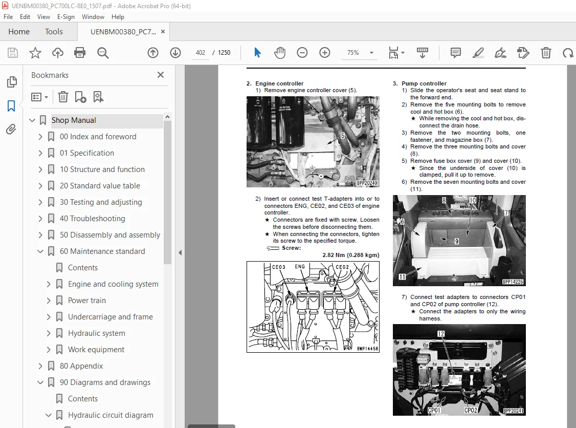
Removal and installation of engine controller assembly 1067
Removal and installation of pump controller assembly 1069
Removal and installation of KOMTRAX terminal assembly 1071
Removal and installation of machine monitor assembly 1072
60 Maintenance standard 1075
Contents 1076
Engine and cooling system 1077
Engine mount 1077
PTO 1079
Cooling system 1080
Power train 1081
Swing circle 1081
Swing machinery 1082
Final drive 1084
Sprocket 1085
Undercarriage and frame 1087
Track frame and idler cushion 1087
Idler 1088
Track roller 1090
Carrier roller 1092
Track shoe 1094
Hydraulic system 1098
Hydraulic pump 1098
Control valve 1108
Swing motor 1114
Travel motor 1115
PPC valve 1118
Boom drift prevention valve 1125
Regeneration valve (boom, arm) 1126
Centre swivel joint 1127
Work equipment 1128
Work equipment 1128
Work equipment dimension 1130
Work equipment cylinder 1134
80 Appendix 1137
Table of contents 1138
Air conditioner 1139
Precautions for refrigerant 1139
Air conditioner component 1140
Configuration and function of refrigeration cycle 1142
Outline of refrigeration cycle 1143
Air conditioner unit 1146
Air conditioner controller 1151
Compressor 1152
Condenser 1153
Receiver drier 1154
Procedure for testing and troubleshooting 1156
Circuit diagram and arrangement of connector pins 1158
System diagram 1160
Detail of air conditioner unit 1162
Parts and connectors layout 1164
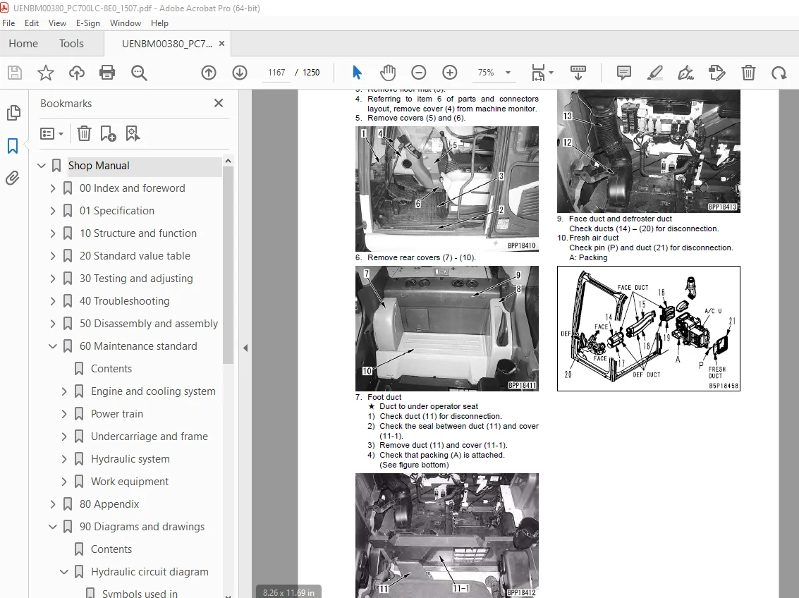
Testing air leakage (duct) 1167
Testing with self-diagnosis function 1168
Testing temperature control 1171
Testing vent (mode) changeover 1173
Testing FRESH/RECIRC air changeover 1176
Testing inner sensor 1178
Testing evaporator temperature sensor 1179
Testing sunlight sensor 1181
Testing (dual) pressure switch for refrigerant 1182
Testing relays 1183
Troubleshooting chart 1 1184
Troubleshooting chart 2 1186
Information in troubleshooting table 1188
Troubleshooting for power supply and CAN communication system (Air conditioner does not operate) 1190
Troubleshooting for compressor and refrigerant system (Air is not cooled) 1195
Troubleshooting for blower motor system (No air comes out or air flow is abnormal) 1199
Troubleshooting for temperature control 1203
Troubleshooting for vent (mode) changeover 1206
Troubleshooting for FRESH/RECIRC air changeover 1208
Troubleshooting for temperature sensor system 1210
Troubleshooting with gauge pressure 1211
Connection of service tool 1214
Precautions for disconnecting and connecting air conditioner piping 1216
Handling of compressor oil 1218
90 Diagrams and drawings 1221
Contents 1222
Hydraulic circuit diagram 1223
Symbols used in hydraulic circuit diagrams 1223
Hydraulic circuit diagram (1/3) Backhoe specification 1227
Hydraulic circuit diagram (2/3) Attachment specification 1229
Hydraulic circuit diagram (3/3) Breaker specification for low back pressure 1231
Electrical circuit diagram 1233
Symbols used in electric circuit diagrams 1233
Electrical circuit diagram Backhoe specification (1/5) 1237
Electrical circuit diagram Backhoe specification (2/5) 1239
Electrical circuit diagram Backhoe specification (3/5) 1241
Electrical circuit diagram Backhoe specification (4/5) 1243
Electrical circuit diagram Backhoe specification (5/5) 1245
Air conditioner electrical circuit diagram 1247
DESCRIPTION:
Komatsu PC700LC-8E0 Hydraulic Excavator Shop Manual UENBM00380 – PDF DOWNLOAD
SERIAL NUMBERS PC700LC-8E0 K50001 and up
How to read the shop manual 0-17
1. Composition of shop manual
This shop manual contains the necessary technical information for services performed in a workshop. For
ease of understanding, the manual is divided into the following sections.
00. Index and foreword
This section contains the index, foreword, safety and basic information. If any revision is made, the LIST
OF REVISED PAGES will be added.
01. Specification
This section explains the specifications of the machine.
10. Structure and function
This section explains the structure and function of each component. It serves not only to give an understanding
for the structure of each component, but also serves as reference material for troubleshooting.
20. Standard value table
This section explains the standard values for new machine and judgement criteria for testing, adjusting,
and troubleshooting. This standard value table is used to check the standard values in testing and adjusting
and to judge parts in troubleshooting.
30. Testing and adjusting
This section explains measuring tools and measuring methods for testing and adjusting, as well as the
adjusting method of each part. The standard values and judgment criteria for “Testing and adjusting” are
explained in “Standard value table”.
40. Troubleshooting
This section explains how to find out failed parts and how to repair them. The troubleshooting is divided
by failure modes. The “S mode” of the troubleshooting related to the engine may be also explained in the
Chassis volume and Engine volume. In this case, see the Chassis volume.
50. Disassembly and assembly
This section explains the special tools and procedures for removing, installing, disassembling, and assembling
each component, as well as precautions for them. In addition, tightening torque, and quantity and
weight of coating material, oil, grease, and coolant necessary for the work are also explained.
60. Maintenance standard
This section gives maintenance standard values of each component. The maintenance standard sub-section
explains the criteria and remedies for disassembly and service.
80. Appendix
This section explains the structure, function, testing, adjusting, and troubleshooting for the equipment not
classifiable in other sections.
90. Diagrams and drawings (chassis volume) /Repair and replacement of parts (engine volume)
q Chassis volume
This section gives hydraulic circuit diagrams and electrical circuit diagrams.
q Engine volume
This section explains the method of re manufacturing and repairing engine and replacing parts.
S.V 28/12/24


