Trusted Business
Verified & Licensed
Virus Free Files
100% Safe Downloads
Secure Payment
SSL Protected
Instant Delivery
Available Immediately
Komatsu PC490-10 PC490LC-10 Hydraulic Excavator Shop Manual UEN05622-02 PDF
$37.95
Komatsu PC490-10 PC490LC-10 Hydraulic Excavator Shop Manual UEN05622-02 – PDF DOWNLOAD
SERIAL NUMBERS
80001 and up
K60001 and up
K60001 and up
Instant PDF Download
Available immediately
Save to Your Device
Download & keep forever
Antivirus Scanned
100% virus-free
Trusted Worldwide
175,000+ customers
Description
Komatsu PC490-10 PC490LC-10 Hydraulic Excavator Shop Manual UEN05622-02 – PDF DOWNLOAD
FILE DETAILS:
Komatsu PC490-10 PC490LC-10 Hydraulic Excavator Shop Manual UEN05622-02 – PDF DOWNLOAD
Language : English
Pages : 1677
Downloadable : Yes
File Type : PDF
IMAGES PREVIEW OF THE MANUAL:
TABLE OF CONTENTS:
Komatsu PC490-10 PC490LC-10 Hydraulic Excavator Shop Manual UEN05622-02 – PDF DOWNLOAD
SERIAL NUMBERS
80001 and up
K60001 and up
K60001 and up
00 Index and foreword 3
Index 4
Foreword, safety and general information 16
Important safety notice 16
How to read the shop manual 23
Explanation of terms for maintenance standard 25
Handling equipment of fuel system devices 27
Handling of intake system parts 28
Handling of hydraulic equipment 29
Method of disconnecting and connecting of push-pull type coupler 31
Handling of electrical equipment 34
How to read electric wire code 42
Precautions when performing operation 45
Practical use of KOMTRAX 49
Standard tightening torque table 50
List of abbreviation 54
Conversion table 59
01 Specifications 65
Table of contents 66
Specifications 67
Specification drawings 67
Working range drawings 68
Specifications 69
Weight table 72
Table of fuel, coolant and lubricants 73
10 Structure and function 75
Table of contents 76
Engine and cooling system 77
Engine-related parts 77
Cooling system 79
Cooling fan pump 82
Cooling fan motor 92
Power train 100
Power train 100
Swing circle 102
Swing machinery 103
Final drive 105
Undercarriage and frame 107
Track frame and idler cushion 107
Hydraulic system 109
Hydraulic component layout 109
Valve control 111
Hydraulic tank 113
CLSS 116
Main pump 121
Control valve 145
Swing motor 199
Travel motor 210
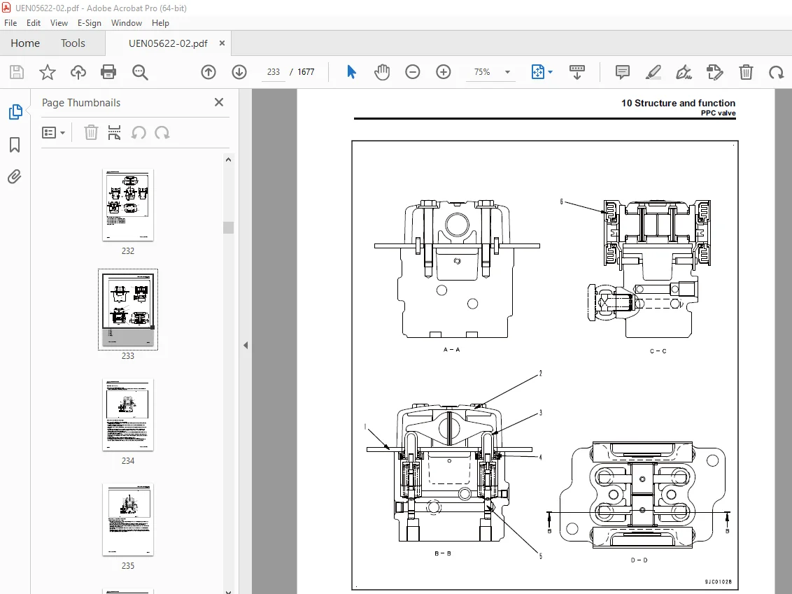
PPC valve 225
Solenoid valve 244
Attachment circuit selector valve 247
Variable pressure compensation valve 250
Center swivel joint 252
Accumulator 254
Hydraulic drift prevention valve 255
ATT EPC valve assembly 260
Return oil filter 262
Quick coupler control valve 263
Work equipment 266
Work equipment 266
Work equipment shims 267
Bucket play adjustment shim 268
Cab and its attachments 269
Cab mount and cab tipping stopper 269
ROPS cab 270
Electrical system 271
Electrical control system 271
Machine monitor system 320
KOMTRAX system 338
Sensor 340
PPC levers 361
Auto grease system 363
20 Standard value table 377
Table of contents 378
Standard service value table 379
Standard value table for engine 379
Standard value table for machine 381
30 Testing and adjusting 395
Table of contents 396
General information on testing and adjusting 397
Tools for testing and adjusting 397
Sketch of tools for testing and adjusting 400
Engine and cooling system 403
Checking engine speed 403
Measuring boost pressure 404
Measuring exhaust gas temperature 405
Measuring exhaust gas color 406
Measuring and adjusting valve clearance 408
Measuring compression pressure 411
Measuring blowby pressure 414
Measuring engine oil pressure 415
Measuring EGR valve and KVGT oil pressure 417
Measuring fuel pressure 418
Measuring fuel leakage and return 420
Bleeding air from fuel system 423
Checking fuel circuit for leakage 425
Handling cylinder cutout mode operation 426
Handling no injection cranking operation 427
Checking and adjusting air conditioner compressor belt tension 428
Replacing alternator belt 429
Fuel doser cleaning procedure 430
Writing compensation values at replacement of injector and engine controller 433
Power train 437
Testing swing circle bearing clearance 437
Undercarriage and frame 438
Testing and adjusting track shoe tension 438
Hydraulic system 439
Releasing remaining pressure from hydraulic circuit 439
Measuring and adjusting oil pressure in work equipment, swing and travel circuits 440
Measuring oil pressure in control circuit 445
Measuring and adjusting oil pressure in pump PC control circuit 446
Measuring and adjusting oil pressure in pump LS control circuit 449
Measuring solenoid valve output pressure 454
Measuring PPC valve output pressure 458
Adjusting play of work equipment and swing PPC valves 460
Measuring and adjusting quick coupler control valve output pressure 461
Testing pump swash plate sensor 462
Measuring fan pump circuit oil pressure 463
Checking fan pump EPC current 464
Measuring fan pump EPC solenoid valve output pressure 465
Isolating the parts causing hydraulic drift in work equipment 466
Measuring oil leakage 467
Bleeding air from hydraulic circuit 470
Cab and its attachments 473
Checking cab tipping stopper 473
Adjusting mirrors 474
Electrical system 477
Special functions of machine monitor 477
Angle adjustment of rear view camera 547
Handling voltage circuit of engine controller 549
Handling battery disconnect switch 550
Testing diodes 551
Pm clinic 552
Check sheet 555
40 Troubleshooting 563
Table of contents 564
General information on troubleshooting 571
Troubleshooting points 571
Sequence of events in troubleshooting 573
Checks before troubleshooting 575
Inspection procedure before troubleshooting 577
Classification and procedure for troubleshooting 583
Symptom and troubleshooting numbers 586
Information in troubleshooting table 589
Connector list and layout 591
Connector contact identification 602
T-branch box and T-branch adapter table 638
Connection table of fuse box 644
Precautions for KDPF (KCSF and KDOC) Cleaning and Replacement 646
Failure codes table 649
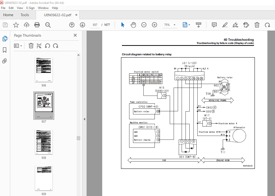
Troubleshooting by failure code (Display of code) 658
Failure code [879AKA] A/C Inner Sensor Open Circuit 658
Failure code [879AKB] A/C Inner Sensor Short Circuit 659
Failure code [879BKA] A/C Outer Sensor Open Circuit 660
Failure code [879BKB] A/C Outer Sensor Short Circuit 661
Failure code [879CKA] Ventilating Sensor Open Circuit 662
Failure code [879CKB] Ventilating Sensor Short Circuit 663
Failure code [879DKZ] Sunlight Sensor Open Or Short Circuit 664
Failure code [879EMC] Ventilation Damper Abnormality 665
Failure code [879FMC] Air Mix Damper Abnormality 666
Failure code [879GKX] Refrigerant Abnormality 667
Failure code [989L00] Engine Controller Lock Caution 1 668
Failure code [989M00] Engine Controller Lock Caution 2 669
Failure code [989N00] Engine Controller Lock Caution 3 670
Failure code [A1U0N3]: KDPF Dry Request (HC Release) 671
Failure code [A1U0N4] KDPF Dry Request (HC Release) 673
Failure code [AA10NX] Air Cleaner Clogging 675
Failure code [AB00KE] Charge Voltage Low 677
Failure code [B@BAZG] Eng Oil Press Low 679
Failure code [B@BAZK] Eng Oil Level Low 680
Failure code [B@BCNS] Eng Water Overheat 681
Failure code [B@BCZK] Eng Water Level Low 682
Failure code [B@HANS] Hyd Oil Overheat 684
Failure code [CA115] Eng Ne and Bkup Speed Sens Error 685
Failure code [CA122] Chg Air Press Sensor High Error 686
Failure code [CA123] Chg Air Press Sensor Low Error 688
Failure code [CA131] Throttle Sensor High Error 690
Failure code [CA132] Throttle Sensor Low Error 692
Failure code [CA135] Eng Oil Press Sensor High Error 694
Failure code [CA141] Eng Oil Press Sensor Low Error 696
Failure code [CA144] Coolant Temp Sens High Error 698
Failure code [CA145] Coolant Temp Sens Low Error 700
Failure code [CA153] Chg Air Temp Sensor High Error 702
Failure code [CA154] Chg Air Temp Sensor Low Error 704
Failure code [CA187] Sensor 2 Supply Volt Low Error 706
Failure code [CA221] Ambient Press Sensor High Error 708
Failure code [CA222] Ambient Press Sensor Low Error 710
Failure code [CA227] Sensor 2 Supply Volt High Error 712
Failure code [CA234] Eng Overspeed 713
Failure code [CA238] Ne Speed Sensor Supply Volt Error 714
Failure code [CA239] Ne Speed Sens Supply Volt High Error 715
Failure code [CA271] IMV/PCV1 Short Error 716
Failure code [CA272] IMV/PCV1 Open Error 717
Failure code [CA273] PCV2 Short Error 718
Failure code [CA274] PCV2 Open Error 719
Failure code [CA322] Inj #1(L#1) Open/Short Error 720
Failure code [CA323] Inj #5(L#5) Open/Short Error 722
Failure code [CA324] Inj #3(L#3) Open/Short Error 724
Failure code [CA325] Inj #6(L#6) Open/Short Error 726
Failure code [CA331] Inj #2(L#2) Open/Short Error 728
Failure code [CA332] Inj #4(L#4) Open/Short Error 730
Failure code [CA343] ECM Critical Internal Failure 732
Failure code [CA351] Injectors Drive Circuit Error 733
Failure code [CA352] Sensor 1 Supply Volt Low Error 734
Failure code [CA356] Mass Air Flow Sensor High Error 736
Failure code [CA357] Mass Air Flow Sensor Low Error 738
Failure code [CA386] Sensor 1 Supply Volt High Error 740
Failure code [CA441] Battery Voltage Low Error 741
Failure code [CA442] Battery Voltage High Error 743
Failure code [CA449] Rail Press Very High Error 744
Failure code [CA451] Rail Press Sensor High Error 745
Failure code [CA452] Rail Press Sensor Low Error 747
Failure code [CA515] Rail Press Sens Sup Volt High Error 749
Failure code [CA516] Rail Press Sens Sup Volt Low Error 751
Failure code [CA553] Rail Press High Error 753
Failure code [CA555] Crankcase Press High Error 1 754
Failure code [CA556] Crankcase Press High Error 2 755
Failure code [CA559] Rail Press Low Error 756
Failure code [CA595] Turbo Speed High Error 2 760
Failure code [CA687] Turbo Speed Low Error 761
Failure code [CA689] Eng Ne Speed Sensor Error 763
Failure code [CA691] Intake Temperature Sensor High Error 765
Failure code [CA692] Intake Temperature Sensor Low Error 767
Failure code [CA697] ECM Internal Temp Sensor High Error 769
Failure code [CA698] ECM Int Temp Sensor Low Error 770
Failure code [CA731] Eng Bkup Speed Sens Phase Error 771
Failure code [CA778] Eng Bkup Speed Sensor Error 772
Failure code [CA1117] Persistent Data Lost Error 774
Failure code [CA1664] KDOC Malfunction 775
Failure code [CA1691] Regeneration Ineffective 778
Failure code [CA1695] Sens supply 5 volt high error 781
Failure code [CA1696] Sens supply 5 volt low error 782
Failure code [CA1843] Crankcase Pressure Sensor High Error 784
Failure code [CA1844] Crankcase Press Sensor Low Error 786
Failure code [CA1879] KDPF Delta Pressure Sensor High Error 788
Failure code [CA1881] KDPF Delta Pressure Sensor Low Error 790
Failure code [CA1883] KDPF Delta Pressure Sensor In Range Error 792
Failure code [CA1921] KDPF Soot Load High Error 1 795
Failure code [CA1922] KDPF Soot Load High Error 2 798
Failure code [CA1923] Dosing Fuel Valve 1 High Error 802
Failure code [CA1924] Dosing Fuel Valve 1 Low Error 804
Failure code [CA1925] Dosing Fuel Valve 1 In Range Error 807
Failure code [CA1927] Dosing Fuel Press Sens High Error 809
Failure code [CA1928] Dosing Fuel Press Sens Low Error 811
Failure code [CA1942] Crankcase Press Sens In Range Error 813
Failure code [CA1963] Dosing Fuel Valve 1 Servo Error 814
Failure code [CA1977] Fuel Doser Open/Short Error 816
Failure code [CA1993] KDPF Delta Pressure Low Error 818
Failure code [CA2185] Throt Sens Sup Volt High Error 820
Failure code [CA2186] Throt Sens Sup Volt Low Error 821
Failure code [CA2249] Rail Press Very Low Error 822
Failure code [CA2265] Fuel feed pump open circuit error 823
Failure code [CA2266] Fuel feed pump short circuit error 825
Failure code [CA2271] EGR Valve Pos Sens High Error 827
Failure code [CA2272] EGR Valve Pos Sens Low Error 829
Failure code [CA2349] EGR Valve Solenoid Open Error 831
Failure code [CA2353] EGR Valve Solenoid Short Error 833
Failure code [CA2357] EGR Valve Servo Error 835
Failure code [CA2381] KVGT Pos Sens High Error 836
Failure code [CA2382] KVGT Pos Sens Low Error 838
Failure code [CA2383] KVGT Solenoid Open Error 840
Failure code [CA2386] KVGT Solenoid Short Error 842
Failure code [CA2387] KVGT Servo Error 844
Failure code [CA2555] Grid Htr Relay Open Circuit Error 845
Failure code [CA2556] Grid Htr Relay Short Circuit Error 847
Failure code [CA2637] KDOC Face Plugging 849
Failure code [CA2639] Manual Stationary Regeneration Request 851
Failure code [CA2732] Dosing Fuel Valve 2 High Error 853
Failure code [CA2733] Dosing Fuel Valve 2 Low Error 855
Failure code [CA2741] Dosing Fuel Valve Swap Error 857
Failure code [CA2765] Inj Trim Data Error 859
Failure code [CA2878] Dosing Fuel Valve 2 Servo Error 860
Failure code [CA2881] Dosing Fuel Pressure Low Error 1 863
Failure code [CA3133] KDPF Outlet Pressure Sensor High Error 866
Failure code [CA3134] KDPF Outlet Pressure Sensor Low Error 868
Failure code [CA3135] KDPF Outlet Pressure Sensor In Range Error 870
Failure code [CA3167] Fuel Doser Degradation 874
Failure code [CA3251] KDOC Inlet Temperature High Error 877
Failure code [CA3253] KDOC Temp Error – Non Regeneration 880
Failure code [CA3254] KDOC Outlet Temp High Error 1 883
Failure code [CA3255] KDPF Temp Error – Non Regeneration 886
Failure code [CA3256] KDPF Outlet Temp High Error 1 890
Failure code [CA3311] KDOC Outlet Temp High Error 2 893
Failure code [CA3312] KDPF Outlet Temp High Error 2 896
Failure code [CA3313] KDOC Inlet Temperature Sensor Low Error 899
Failure code [CA3314] KDOC Inlet Temperature Sensor High Error 902
Failure code [CA3315] KDOC Intlet Temperature Sensor In Range Error 906
Failure code [CA3316] KDOC Outlet Temperature Sensor Low Error 910
Failure code [CA3317] KDOC Outlet Temperature Sensor High Error 913
Failure code [CA3318] KDOC Outlet Temp Sensor In Range Error 917
Failure code [CA3319] KDPF Outlet Temperature Sensor High Error 921
Failure code [CA3321] KDPF Outlet Temperature Sensor Low Error 925
Failure code [CA3322] KDPF Outlet Temp Sensor In Range Error 928
Failure code [CA3419] Mass Air Flow Sensor Power Supply High Error 932
Failure code [CA3421] Mass Air Flow Sensor Power Supply Low Error 934
Failure code [D110KB] Battery Relay Drive S/C 936
Failure code [D19JKZ] Personal Code Relay Abnormality 938
Failure code [D811MC] KOMTRAX Error 941
Failure code [D862KA] GPS Antenna Open Circuit 942
Failure code [D8ALKA] System Operating Lamp Disconnection (KOMTRAX) 943
Failure code [D8ALKB] System Operating Lamp Short Circuit (KOMTRAX) 945
Failure code [D8AQKR] CAN2 Discon (KOMTRAX) 946
Failure code [DA20MC] Pump Controller Malfunction 947
Failure code [DA22KK] Pump Solenoid Power Low Error 948
Failure code [DA25KP] 5V Sensor1 Power Abnormality 950
Failure code [DA29KQ] Model Selection Abnormality 953
Failure code [DA2LKA] System Operating Lamp Disconnection (Pump Con) 956
Failure code [DA2LKB] System Operating Lamp Short Circuit (Pump Con) 958
Failure code [DA2QKR] CAN2 Discon ( Pump Con) 959
Failure code [DA2RKR] CAN1 Discon ( Pump Con) 962
Failure code [DAF0MB] Monitor ROM Abnormality 963
Failure code [DAF0MC] Monitor Error 964
Failure code [DAF8KB] Camera Power Supply Short Circuit 965
Failure code [DAF9KQ] Model Selection Abnormality 967
Failure code [DAFGMC] GPS Module Error 968
Failure code [DAFLKA] Operating Lamp Open Circuit(Monitor) 969
Failure code [DAFLKB] System Operating Lamp Short Circuit (Monitor) 971
Failure code [DAFQKR] CAN2 Discon 972
Failure code [DAZ9KQ] AC Model Selection Abnormality 973
Failure code [DAZQKR] CAN2 Discon (AC) 974
Failure code [DB2QKR] CAN2 Discon (Engine Con) 979
Failure code [DB2RKR] CAN1 Discon (Engine Con) 984
Failure code [DGH2KA] Hyd Oil Temp Sensor Open 989
Failure code [DGH2KB] Hyd Oil Sensor Short 991
Failure code [DHA4KA] Air Cleaner Clogging Sensor Open Circuit 993
Failure code [DHPAMA] Pump Press Sensor Abnormality 994
Failure code [DHPBMA] R Pump Press Sensor Abnormality 997
Failure code [DHS3MA] Arm IN PPC Sen Abnormality 1000
Failure code [DHS4MA] Bucket CURL PPC Press Sensor Abnormality 1002
Failure code [DHS8MA] Boom RAISE PPC Press Sensor Abnormality 1005
Failure code [DHS9MA] Boom LOWER Press Sensor Abnormality 1008
Failure code [DHSAMA] Swing RH PPC Press Sensor Abnomality 1011
Failure code [DHSBMA] Swing LH PPC Press Sensor Abnomality 1014
Failure code [DHSCMA] Arm OUT PPC Press Sensor Abnormality 1017
Failure code [DHSDMA] Bucket Dump PPC Press Sensor Abnormality 1020
Failure code [DHSFMA] Travel FW L PPC Press Sensor Abnormality 1023
Failure code [DHSGMA] Travel FW R PPC Press Sensor Abnormality 1026
Failure code [DHSHMA] Travel BW L PPC Press Sensor Abnormality 1029
Failure code [DHSJMA] Travel BW R PPC Press Sensor Abnormality 1032
Failure code [DKR0MA] F pump S/P sensor Abnormality 1035
Failure code [DKR1MA] R pump S/P sensor Abnormality 1037
Failure code [DLM3KA] Fan speed sensor: Open circuit 1039
Failure code [DLM3KB] Fan speed sensor: Short circuit 1040
Failure code [DLM3MB] Fan Control Mismatch 1041
Failure code [DV20KB] Travel alarm short circuit 1042
Failure code [DW43KA] Travel Speed Sol Open Circuit 1044
Failure code [DW43KB] Travel Speed Sol Short Circuit 1046
Failure code [DW45KA] swing holding brake Sol Open Circuit 1048
Failure code [DW45KB] Swing Brake Sol Short Circuit 1051
Failure code [DW7BKA] Fan Reverse Sol Open Circuit 1053
Failure code [DW7BKB] Fan Reverse Sol Short Circuit 1055
Failure code [DW91KA] Travel Junction Sol Open Circuit 1057
Failure code [DW91KB] Travel Junction Sol Short Circuit 1059
Failure code [DWA2KA] Attachment Sol Open Circuit 1061
Failure code [DWA2KB] Attachment Sol Short Circuit 1063
Failure code [DWK0KA] 2-stage Relief Sol Open Circuit 1065
Failure code [DWK0KB] 2-stage Relief Sol Short Circuit 1067
Failure code [DWK2KA] Variable Back Pressure Sol Open Circuit 1069
Failure code [DWK2KB] Variable Back Pressure Sol Short Circuit 1071
Failure code [DWK8KA] Swing C/O Solenoid Open Circuit 1073
Failure code [DWK8KB] Swing C/O Solenoid Short Circuit 1075
Failure code [DX16KA] Fan Pump EPC Sol Open Circuit 1077
Failure code [DX16KB] Fan Pump EPC Sol Short Circuit 1079
Failure code [DXA8KA] PC-EPC (F) Sol Open Circuit 1081
Failure code [DXA8KB] PC-EPC (F) Sol Short Circuit 1083
Failure code [DXA9KA] PC-EPC (R) Sol Open Circuit 1085
Failure code [DXA9KB] PC-EPC (R) Sol Short Circuit 1087
Failure code [DXE0KA] LS-EPC Sol Open Circuit 1089
Failure code [DXE0KB] LS-EPC Sol Short Circuit 1091
Failure code [DXE4KA] Service Current EPC Disc 1093
Failure code [DXE4KB] Service Current EPC S/C 1094
Failure code [DXE5KA] Merge-divider Main Sol Open Circuit 1095
Failure code [DXE5KB] Merge-divider Main Sol Short Circuit 1097
Failure code [DXE6KA] Merge-divider LS Sol Open Circuit 1099
Failure code [DXE6KB] Merge-divider LS Sol Short Circuit 1101
Failure code [DY20KA] Wiper Working Abnormality 1103
Failure code [DY20MA] Wiper Parking Abnormality 1105
Failure code [DY2DKB] Wiper Drive (For) Short 1107
Failure code [DY2EKB] Wiper Drive (Rev) Short 1109
Troubleshooting of electrical system (E-mode) 1111
E-1 Engine does not start (Engine does not crank) 1111
E-2 Manual preheater does not operate 1117
E-3 Automatic preheater does not operate 1120
E-4 While preheater is operating, engine preheating monitor does not light up 1122
E-5 While starting switch is turned ON, machine monitor displays nothing 1124
E-6 While starting switch is turned to ON position (with engine stopped), engine oil level monitor lights up in yellow 1127
E-7 While starting switch is turned to ON position (with engine stopped), radiator coolant level monitor lights up in yellow 1128
E-8 Engine coolant temperature monitor lights up in white while engine is running 1129
E-9 Hydraulic oil temperature monitor lights up in white while engine is running 1130
E-10 Charge level monitor lights up while engine is running 1131
E-11 Fuel level monitor lights up in red while engine is running 1132
E-12 Air cleaner clogging monitor lights up in yellow while engine is running 1133
E-13 Engine coolant temperature monitor lights up in red while engine is running 1134
E-14 Hydraulic oil temperature monitor lights up in red while engine is running 1135
E-15 Engine oil pressure monitor lights up in red while engine is running 1136
E-16 Fuel gauge display does not move from minimum or maximum 1137
E-17 Display of fuel gauge differs from actual fuel level 1138
E-18 Engine coolant temperature gauge display does not move from minimum or maximum 1139
E-19 Display of engine coolant temperature gauge differs from actual coolant temperature 1140
E-20 Hydraulic oil temperature gauge display does not move from minimum or maximum 1141
E-21 Display of hydraulic oil temperature gauge differs from actual oil temperature 1143
E-22 Machine monitor does not display partially 1144
E-23 Function switch does not operate 1145
E-24 Automatic warm-up system does not work (in cold weather) 1146
E-25 When auto-decelerator switch is operated, auto-decelerator monitor does not light up or does not go off 1147
E-26 Auto-decelerator is not operated or canceled with lever 1148
E-27 When working mode switch is operated, working mode selection screen is not displayed 1149
E-28 When working mode is changed, setting of engine and hydraulic pump is not changed 1150
E-29 When travel speed switch is operated, travel speed monitor does not change 1151
E-30 When travel speed selection is changed, actual travel speed does not change 1152
E-31 Alarm buzzer cannot be canceled 1153
E-32 When starting switch is turned OFF, service meter is not displayed 1154
E-33 Machine monitor cannot be set in service mode 1155
E-34 All of work equipments, swing, and travel mechanism do not move 1156
E-35 All of work equipment, swing, and travel mechanism do not lock 1158
E-36 When swing brake cancel switch is set to CANCEL position, machine cannot swing 1159
E-37 When swing brake cancel switch is set to Normal position, swing holding brake does not operate 1161
E-38 One-touch power maximizing function does not operate properly, or indicator not displayed on monitor 1163
E-39 One-touch power maximizing function is not cancelled 1165
E-40 Alarm does not sound during travel 1166
E-41 Alarm does not stop sounding while machine is stopped 1168
E-42 Horn does not sound 1169
E-43 Horn does not stop sounding 1171
E-44 When wiper switch is operated, wiper monitor does not light up or go off 1172
E-45 When wiper switch is operated, windshield wiper does not operate 1173
E-46 When window washer switch is operated, window washer does not operate 1175
E-47 Boom LOWER indicator is not displayed properly with monitoring function 1176
E-48 Arm OUT indicator is not displayed properly with monitoring function 1177
E-49 Arm IN indicator is not displayed properly with monitoring function 1178
E-50 Boom RAISE indicator is not displayed properly with monitoring function 1179
E-51 Bucket CURL indicator is not displayed properly with monitoring function 1180
E-52 Bucket DUMP indicator is not displayed properly with monitoring function 1181
E-53 Swing indicator is not displayed properly with monitoring function 1182
E-54 Travel indicator is not displayed properly with monitoring function 1183
E-55 Service indicator is not displayed properly with monitoring function 1184
E-56 Attachment hydraulic circuit cannot be changed 1186
E-57 KOMTRAX system does not operate properly 1187
E-58 Machine push-up function cannot be canceled 1189
E-59 Machine push-up function does not operate 1191
Troubleshooting of hydraulic and mechanical system (H-mode) 1192
Information described in troubleshooting table (H-mode) 1192
System diagram of hydraulic equipment system 1193
Failure mode and cause table 1195
H-1 Speed or power of all work equipment, swing, and travel is low 1201
H-2 Engine speed lowers significantly or engine stalls 1203
H-3 Any of work equipment, swing and travel does not work 1205
H-4 Unusual sound is heard from around hydraulic pump 1206
H-5 Fine control performance or response is poor 1207
H-6 Speed or power of boom is low 1208
H-7 Speed or power of arm is low 1212
H-8 Speed or power of bucket is low 1216
H-9 Work equipment does not move in single operation 1219
H-10 Hydraulic drift of work equipment is large 1220
H-11 Time lag of work equipment is large 1224
H-12 Other work equipment moves when one of work equipment is relieved 1225
H-13 One-touch power maximizing function does not work 1226
H-14 Machine push-up function does not work 1227
H-15 In combined operation of work equipment , equipment having heavier load moves slower 1228
H-16 In combined operation of swing and boom RAISE, boom rising speed is low 1229
H-17 Travel speed drops largely in combined operation of swing and trave 1230
H-18 Machine does not travel straight 1231
H-19 Travel speed is low 1233
H-20 Machine is hard to steer or travel power is low 1235
H-21 Travel speed does not change, or travel speed is too low or high 1237
H-22 One of tracks does not run 1238
H-23 Upper structure does not swing 1239
H-24 Swing acceleration is poor or swing speed is low 1241
H-25 Upper structure overruns excessively when it stops swinging 1243
H-26 Shock is large when upper structure stops swinging 1245
H-27 Large unusual noise is heard when upper structure stops swinging 1246
H-28 Swing drift on a slope is large 1247
H-29 Attachment circuit cannot be changed 1249
H-30 Oil flow in attachment circuit cannot be controlled 1250
H-31 Fan speed is abnormal (high, low, or 0 rpm) 1251
H-32 Unusual noise is heard from around fan 1252
H-33 Quick coupler cylinder will not extend 1253
H-34 Quick coupler cylinder will not extend (but buzzer does not sound) 1255
H-35 Buzzer does not sound (but quick coupler cylinder does retract) 1257
H-36 Quick coupler cylinder extends and retracts slowly 1259
Troubleshooting of engine (S-mode) 1260
Information mentioned in troubleshooting table (S mode) 1260
S-1 When starting switch is turned to START position, engine is not cranked 1261
S-2 The engine cranks but exhaust smoke does not come out 1262
S-3 Fuel is injected but engine does not start (incomplete combustion, engine seems to start but does not) 1263
S-4 Startability is poor 1264
S-5 Engine does not pick-up smoothly 1267
S-6 Engine stops during operation 1270
S-7 Engine runs rough or is unstable 1272
S-8 Engine lacks power 1273
S-9 Exhaust gas is black (KDPF gets clogged in a short time) 1275
S-10 Engine oil consumption is excessive 1277
S-11 Engine oil becomes contaminated early 1278
S-12 Fuel consumption is excessive 1279
S-13 Oil is in coolant (or coolant spurts or coolant level goes down) 1280
S-14 Oil pressure drops 1281
S-15 Fuel mixes into engine oil 1282
S-16 Water mixes into engine oil (milky) 1283
S-17 Coolant temperature rises too high (overheating) 1284
S-18 Unusual noise is heard 1285
S-19 Vibration is excessive 1286
S-20 Air cannot be bled from fuel circuit 1287
S-21 Active regeneration is executed frequently 1288
S-22 Active regeneration takes a long time 1289
S-23 White smoke is exhausted during active regeneration 1290
Auto grease system 1291
Finding malfunctions 1291
Malfunction finding procedures 1294
50 Disassembly and assembly 1297
Table of contents 1298
General information on disassembly and assembly 1300
How to read this manual 1300
Coating materials list 1302
Special tools list 1306
Sketches of special tools 1310
Engine and cooling system 1315
Removal and installation of supply pump assembly 1315
Removal and installation of injector assembly 1322
Removal and installation of cylinder head assembly 1329
Removal and installation of radiator assembly 1337
Removal and installation of hydraulic oil cooler assembly 1340
Removal and installation of aftercooler assembly 1342
Removal and installation of cooling fan and fan motor assembly 1344
Removal and installation of engine and main pump assembly 1348
Removal and installation of engine front seal 1358
Removal and installation of engine rear seal 1362
Removal and installation of engine hood assembly 1367
Removal and installation of KDPF assembly 1368
Removal and installation of KCCV assembly 1370
Removal and installation of air cleaner assembly 1371
Power train system 1373
Removal and installation of travel motor and final drive assembly 1373
Disassembly and assembly of final drive 1374
Removal and installation of swing motor and swing machinery assembly 1382
Disassembly and assembly of swing machinery 1384
Removal and installation of swing circle assembly 1391
Undercarriage and frame 1392
Separation and connection of track shoe assembly 1392
Removal and installation of sprocket 1394
Removal and installation of idler and idler cushion assembly 1395
Disassembly and assembly of idler 1396
Disassembly and assembly of idler cushion 1399
Disassembly and assembly of track roller 1401
Disassembly and assembly of carrier roller 1402
Removal and installation of revolving frame assembly 1404
Removal and installation of counterweight assembly 1406
Hydraulic system 1408
Removal and installation of center swivel joint assembly 1408
Disassembly and assembly of center swivel joint 1410
Removal and installation of hydraulic tank assembly 1411
Removal and installation of main pump assembly 1415
Removal and installation of control valve assembly 1419
Disassembly and assembly of control valve 1423
Disassembly and assembly of work equipment PPC valve 1428
Disassembly and assembly of travel PPC valve 1430
Removal and installation of quick coupler valve 1432
Work equipment 1433
Removal and installation of work equipment assembly 1433
Disassembly and assembly of work equipment cylinder 1436
Cab and its attachments 1441
Removal and installation of operator’s cab assembly 1441
Removal and installation of operator’s cab glass (adhered window glass) 1446
Removal and installation of front window assembly 1456
Removal and installation of floor frame assembly 1462
Removal and installation of air conditioner unit assembly 1468
Removal and installation of operator’s seat 1472
Removal and installation of seat belt 1474
Removal and installation of front wiper assembly 1475
Electrical system 1482
Removal and installation of air conditioner compressor assembly 1482
Removal and installation of air conditioner condenser assembly 1485
Removal and installation of engine controller assembly 1487
Removal and installation of pump controller assembly 1489
Removal and installation of machine monitor assembly 1492
Removal and installation of pump swash plate sensor 1494
Removal and installation of mass air flow and temperature sensor 1495
Removal and installation of KOMTRAX terminal assembly 1497
60 Maintenance standard 1499
Table of contents 1500
Engine and cooling system 1501
Engine mount 1501
Cooling system 1502
Cooling fan pump 1503
Cooling fan motor 1505
Power train system 1506
Swing circle 1506
Swing machinery 1507
Final drive 1509
Undercarriage and frame 1511
Sprocket 1511
Track frame and idler cushion 1513
Idler 1514
Track roller 1516
Carrier roller 1517
Track shoe 1518
Hydraulic system 1521
Main pump 1521
Control valve 1523
Swing motor 1534
Travel motor 1536
PPC valve 1539
Solenoid valve 1549
Attachment circuit selector valve 1550
Hydraulic drift prevention valve 1551
Center swivel joint 1553
Work equipment 1554
Work equipment 1554
Work equipment cylinder 1563
80 Appendix 1567
Table of contents 1568
Air conditioner components 1569
Precautions for refrigerant 1569
Air conditioner component 1570
Configuration and function of refrigeration cycle 1573
Outline of refrigeration cycle 1574
Air conditioner unit 1576
Dual pressure switch 1582
Air conditioner controller 1583
Compressor 1584
Condenser 1585
Receiver drier 1586
Sunlight sensor 1587
Outer temperature sensor (outside air temperature sensor) 1588
Procedure for testing and troubleshooting 1589
Circuit diagram and arrangement of connector pins 1591
System diagram 1593
Input and output signals of the air conditioner controller 1594
Parts and connectors layout 1596
Layout of air conditioner related parts and connectors 1597
Testing air leakage (duct) 1600
Testing with self-diagnosis function 1603
How to enter air conditioner “Electrical Systems” screen in service mode of the machine monitor 1604
Testing vent (mode) changeover 1606
Testing FRESH/RECIRC air changeover 1608
Testing sunlight sensor 1609
Testing (dual) pressure switch for refrigerant 1610
Testing relays 1611
Troubleshooting chart 1 1612
Troubleshooting chart 2 1613
Information in troubleshooting table 1616
Failure code list related to air conditioner 1617
Failure code [879AKA] A/C Inner sensor Open Circuit 1618
Failure code [879AKB] A/C Inner sensor Short Circuit 1619
Failure code [879BKA] A/C Outer sensor Open Circuit 1620
Failure code [879BKB] A/C Outer sensor Short Circuit 1622
Failure code [879CKA] Ventilating sensor Open Circuit 1624
Failure code [879CKB] Ventilating sensor Short Circuit 1625
Failure code [879DKZ] Sunlight sensor Open or Short Circuit 1626
Failure code [879EMC] Ventilating Damper Abnormality 1628
Failure code [879FMC] Air Mix Damper Abnormality 1629
Failure code [879GKX] Refrigerant Abnormality 1630
A-1 Troubleshooting for power supply system (Air conditioner does not operate) 1631
A-2 Troubleshooting of compressor system (Air is not cooled) 1633
A-3 Troubleshooting for blower motor system (No air comes out or air flow is abnormal) 1636
A-4 Troubleshooting for FRESH/RECIRC air changeover 1638
Troubleshooting with gauge pressure 1640
Connection of service tool 1643
Precautions for disconnecting and connecting air conditioner piping 1645
Handling of compressor oil 1647
90 Diagrams and drawings 1649
Table of contents 1650
Hydraulic circuit diagram 1651
Symbols in hydraulic circuit diagram 1651
Hydraulic circuit diagram 0
Electric circuit diagram 1655
Symbols in electric circuit diagram 1655
Electric circuit diagram 0
Electric circuit diagram for air conditioner unit 0
Index 4
Foreword, safety and general information 16
Important safety notice 16
How to read the shop manual 23
Explanation of terms for maintenance standard 25
Handling equipment of fuel system devices 27
Handling of intake system parts 28
Handling of hydraulic equipment 29
Method of disconnecting and connecting of push-pull type coupler 31
Handling of electrical equipment 34
How to read electric wire code 42
Precautions when performing operation 45
Practical use of KOMTRAX 49
Standard tightening torque table 50
List of abbreviation 54
Conversion table 59
01 Specifications 65
Table of contents 66
Specifications 67
Specification drawings 67
Working range drawings 68
Specifications 69
Weight table 72
Table of fuel, coolant and lubricants 73
10 Structure and function 75
Table of contents 76
Engine and cooling system 77
Engine-related parts 77
Cooling system 79
Cooling fan pump 82
Cooling fan motor 92
Power train 100
Power train 100
Swing circle 102
Swing machinery 103
Final drive 105
Undercarriage and frame 107
Track frame and idler cushion 107
Hydraulic system 109
Hydraulic component layout 109
Valve control 111
Hydraulic tank 113
CLSS 116
Main pump 121
Control valve 145
Swing motor 199
Travel motor 210
PPC valve 225
Solenoid valve 244
Attachment circuit selector valve 247
Variable pressure compensation valve 250
Center swivel joint 252
Accumulator 254
Hydraulic drift prevention valve 255
ATT EPC valve assembly 260
Return oil filter 262
Quick coupler control valve 263
Work equipment 266
Work equipment 266
Work equipment shims 267
Bucket play adjustment shim 268
Cab and its attachments 269
Cab mount and cab tipping stopper 269
ROPS cab 270
Electrical system 271
Electrical control system 271
Machine monitor system 320
KOMTRAX system 338
Sensor 340
PPC levers 361
Auto grease system 363
20 Standard value table 377
Table of contents 378
Standard service value table 379
Standard value table for engine 379
Standard value table for machine 381
30 Testing and adjusting 395
Table of contents 396
General information on testing and adjusting 397
Tools for testing and adjusting 397
Sketch of tools for testing and adjusting 400
Engine and cooling system 403
Checking engine speed 403
Measuring boost pressure 404
Measuring exhaust gas temperature 405
Measuring exhaust gas color 406
Measuring and adjusting valve clearance 408
Measuring compression pressure 411
Measuring blowby pressure 414
Measuring engine oil pressure 415
Measuring EGR valve and KVGT oil pressure 417
Measuring fuel pressure 418
Measuring fuel leakage and return 420
Bleeding air from fuel system 423
Checking fuel circuit for leakage 425
Handling cylinder cutout mode operation 426
Handling no injection cranking operation 427
Checking and adjusting air conditioner compressor belt tension 428
Replacing alternator belt 429
Fuel doser cleaning procedure 430
Writing compensation values at replacement of injector and engine controller 433
Power train 437
Testing swing circle bearing clearance 437
Undercarriage and frame 438
Testing and adjusting track shoe tension 438
Hydraulic system 439
Releasing remaining pressure from hydraulic circuit 439
Measuring and adjusting oil pressure in work equipment, swing and travel circuits 440
Measuring oil pressure in control circuit 445
Measuring and adjusting oil pressure in pump PC control circuit 446
Measuring and adjusting oil pressure in pump LS control circuit 449
Measuring solenoid valve output pressure 454
Measuring PPC valve output pressure 458
Adjusting play of work equipment and swing PPC valves 460
Measuring and adjusting quick coupler control valve output pressure 461
Testing pump swash plate sensor 462
Measuring fan pump circuit oil pressure 463
Checking fan pump EPC current 464
Measuring fan pump EPC solenoid valve output pressure 465
Isolating the parts causing hydraulic drift in work equipment 466
Measuring oil leakage 467
Bleeding air from hydraulic circuit 470
Cab and its attachments 473
Checking cab tipping stopper 473
Adjusting mirrors 474
Electrical system 477
Special functions of machine monitor 477
Angle adjustment of rear view camera 547
Handling voltage circuit of engine controller 549
Handling battery disconnect switch 550
Testing diodes 551
Pm clinic 552
Check sheet 555
40 Troubleshooting 563
Table of contents 564
General information on troubleshooting 571
Troubleshooting points 571
Sequence of events in troubleshooting 573
Checks before troubleshooting 575
Inspection procedure before troubleshooting 577
Classification and procedure for troubleshooting 583
Symptom and troubleshooting numbers 586
Information in troubleshooting table 589
Connector list and layout 591
Connector contact identification 602
T-branch box and T-branch adapter table 638
Connection table of fuse box 644
Precautions for KDPF (KCSF and KDOC) Cleaning and Replacement 646
Failure codes table 649
Troubleshooting by failure code (Display of code) 658
Failure code [879AKA] A/C Inner Sensor Open Circuit 658
Failure code [879AKB] A/C Inner Sensor Short Circuit 659
Failure code [879BKA] A/C Outer Sensor Open Circuit 660
Failure code [879BKB] A/C Outer Sensor Short Circuit 661
Failure code [879CKA] Ventilating Sensor Open Circuit 662
Failure code [879CKB] Ventilating Sensor Short Circuit 663
Failure code [879DKZ] Sunlight Sensor Open Or Short Circuit 664
Failure code [879EMC] Ventilation Damper Abnormality 665
Failure code [879FMC] Air Mix Damper Abnormality 666
Failure code [879GKX] Refrigerant Abnormality 667
Failure code [989L00] Engine Controller Lock Caution 1 668
Failure code [989M00] Engine Controller Lock Caution 2 669
Failure code [989N00] Engine Controller Lock Caution 3 670
Failure code [A1U0N3]: KDPF Dry Request (HC Release) 671
Failure code [A1U0N4] KDPF Dry Request (HC Release) 673
Failure code [AA10NX] Air Cleaner Clogging 675
Failure code [AB00KE] Charge Voltage Low 677
Failure code [B@BAZG] Eng Oil Press Low 679
Failure code [B@BAZK] Eng Oil Level Low 680
Failure code [B@BCNS] Eng Water Overheat 681
Failure code [B@BCZK] Eng Water Level Low 682
Failure code [B@HANS] Hyd Oil Overheat 684
Failure code [CA115] Eng Ne and Bkup Speed Sens Error 685
Failure code [CA122] Chg Air Press Sensor High Error 686
Failure code [CA123] Chg Air Press Sensor Low Error 688
Failure code [CA131] Throttle Sensor High Error 690
Failure code [CA132] Throttle Sensor Low Error 692
Failure code [CA135] Eng Oil Press Sensor High Error 694
Failure code [CA141] Eng Oil Press Sensor Low Error 696
Failure code [CA144] Coolant Temp Sens High Error 698
Failure code [CA145] Coolant Temp Sens Low Error 700
Failure code [CA153] Chg Air Temp Sensor High Error 702
Failure code [CA154] Chg Air Temp Sensor Low Error 704
Failure code [CA187] Sensor 2 Supply Volt Low Error 706
Failure code [CA221] Ambient Press Sensor High Error 708
Failure code [CA222] Ambient Press Sensor Low Error 710
Failure code [CA227] Sensor 2 Supply Volt High Error 712
Failure code [CA234] Eng Overspeed 713
Failure code [CA238] Ne Speed Sensor Supply Volt Error 714
Failure code [CA239] Ne Speed Sens Supply Volt High Error 715
Failure code [CA271] IMV/PCV1 Short Error 716
Failure code [CA272] IMV/PCV1 Open Error 717
Failure code [CA273] PCV2 Short Error 718
Failure code [CA274] PCV2 Open Error 719
Failure code [CA322] Inj #1(L#1) Open/Short Error 720
Failure code [CA323] Inj #5(L#5) Open/Short Error 722
Failure code [CA324] Inj #3(L#3) Open/Short Error 724
Failure code [CA325] Inj #6(L#6) Open/Short Error 726
Failure code [CA331] Inj #2(L#2) Open/Short Error 728
Failure code [CA332] Inj #4(L#4) Open/Short Error 730
Failure code [CA343] ECM Critical Internal Failure 732
Failure code [CA351] Injectors Drive Circuit Error 733
Failure code [CA352] Sensor 1 Supply Volt Low Error 734
Failure code [CA356] Mass Air Flow Sensor High Error 736
Failure code [CA357] Mass Air Flow Sensor Low Error 738
Failure code [CA386] Sensor 1 Supply Volt High Error 740
Failure code [CA441] Battery Voltage Low Error 741
Failure code [CA442] Battery Voltage High Error 743
Failure code [CA449] Rail Press Very High Error 744
Failure code [CA451] Rail Press Sensor High Error 745
Failure code [CA452] Rail Press Sensor Low Error 747
Failure code [CA515] Rail Press Sens Sup Volt High Error 749
Failure code [CA516] Rail Press Sens Sup Volt Low Error 751
Failure code [CA553] Rail Press High Error 753
Failure code [CA555] Crankcase Press High Error 1 754
Failure code [CA556] Crankcase Press High Error 2 755
Failure code [CA559] Rail Press Low Error 756
Failure code [CA595] Turbo Speed High Error 2 760
Failure code [CA687] Turbo Speed Low Error 761
Failure code [CA689] Eng Ne Speed Sensor Error 763
Failure code [CA691] Intake Temperature Sensor High Error 765
Failure code [CA692] Intake Temperature Sensor Low Error 767
Failure code [CA697] ECM Internal Temp Sensor High Error 769
Failure code [CA698] ECM Int Temp Sensor Low Error 770
Failure code [CA731] Eng Bkup Speed Sens Phase Error 771
Failure code [CA778] Eng Bkup Speed Sensor Error 772
Failure code [CA1117] Persistent Data Lost Error 774
Failure code [CA1664] KDOC Malfunction 775
Failure code [CA1691] Regeneration Ineffective 778
Failure code [CA1695] Sens supply 5 volt high error 781
Failure code [CA1696] Sens supply 5 volt low error 782
Failure code [CA1843] Crankcase Pressure Sensor High Error 784
Failure code [CA1844] Crankcase Press Sensor Low Error 786
Failure code [CA1879] KDPF Delta Pressure Sensor High Error 788
Failure code [CA1881] KDPF Delta Pressure Sensor Low Error 790
Failure code [CA1883] KDPF Delta Pressure Sensor In Range Error 792
Failure code [CA1921] KDPF Soot Load High Error 1 795
Failure code [CA1922] KDPF Soot Load High Error 2 798
Failure code [CA1923] Dosing Fuel Valve 1 High Error 802
Failure code [CA1924] Dosing Fuel Valve 1 Low Error 804
Failure code [CA1925] Dosing Fuel Valve 1 In Range Error 807
Failure code [CA1927] Dosing Fuel Press Sens High Error 809
Failure code [CA1928] Dosing Fuel Press Sens Low Error 811
Failure code [CA1942] Crankcase Press Sens In Range Error 813
Failure code [CA1963] Dosing Fuel Valve 1 Servo Error 814
Failure code [CA1977] Fuel Doser Open/Short Error 816
Failure code [CA1993] KDPF Delta Pressure Low Error 818
Failure code [CA2185] Throt Sens Sup Volt High Error 820
Failure code [CA2186] Throt Sens Sup Volt Low Error 821
Failure code [CA2249] Rail Press Very Low Error 822
Failure code [CA2265] Fuel feed pump open circuit error 823
Failure code [CA2266] Fuel feed pump short circuit error 825
Failure code [CA2271] EGR Valve Pos Sens High Error 827
Failure code [CA2272] EGR Valve Pos Sens Low Error 829
Failure code [CA2349] EGR Valve Solenoid Open Error 831
Failure code [CA2353] EGR Valve Solenoid Short Error 833
Failure code [CA2357] EGR Valve Servo Error 835
Failure code [CA2381] KVGT Pos Sens High Error 836
Failure code [CA2382] KVGT Pos Sens Low Error 838
Failure code [CA2383] KVGT Solenoid Open Error 840
Failure code [CA2386] KVGT Solenoid Short Error 842
Failure code [CA2387] KVGT Servo Error 844
Failure code [CA2555] Grid Htr Relay Open Circuit Error 845
Failure code [CA2556] Grid Htr Relay Short Circuit Error 847
Failure code [CA2637] KDOC Face Plugging 849
Failure code [CA2639] Manual Stationary Regeneration Request 851
Failure code [CA2732] Dosing Fuel Valve 2 High Error 853
Failure code [CA2733] Dosing Fuel Valve 2 Low Error 855
Failure code [CA2741] Dosing Fuel Valve Swap Error 857
Failure code [CA2765] Inj Trim Data Error 859
Failure code [CA2878] Dosing Fuel Valve 2 Servo Error 860
Failure code [CA2881] Dosing Fuel Pressure Low Error 1 863
Failure code [CA3133] KDPF Outlet Pressure Sensor High Error 866
Failure code [CA3134] KDPF Outlet Pressure Sensor Low Error 868
Failure code [CA3135] KDPF Outlet Pressure Sensor In Range Error 870
Failure code [CA3167] Fuel Doser Degradation 874
Failure code [CA3251] KDOC Inlet Temperature High Error 877
Failure code [CA3253] KDOC Temp Error – Non Regeneration 880
Failure code [CA3254] KDOC Outlet Temp High Error 1 883
Failure code [CA3255] KDPF Temp Error – Non Regeneration 886
Failure code [CA3256] KDPF Outlet Temp High Error 1 890
Failure code [CA3311] KDOC Outlet Temp High Error 2 893
Failure code [CA3312] KDPF Outlet Temp High Error 2 896
Failure code [CA3313] KDOC Inlet Temperature Sensor Low Error 899
Failure code [CA3314] KDOC Inlet Temperature Sensor High Error 902
Failure code [CA3315] KDOC Intlet Temperature Sensor In Range Error 906
Failure code [CA3316] KDOC Outlet Temperature Sensor Low Error 910
Failure code [CA3317] KDOC Outlet Temperature Sensor High Error 913
Failure code [CA3318] KDOC Outlet Temp Sensor In Range Error 917
Failure code [CA3319] KDPF Outlet Temperature Sensor High Error 921
Failure code [CA3321] KDPF Outlet Temperature Sensor Low Error 925
Failure code [CA3322] KDPF Outlet Temp Sensor In Range Error 928
Failure code [CA3419] Mass Air Flow Sensor Power Supply High Error 932
Failure code [CA3421] Mass Air Flow Sensor Power Supply Low Error 934
Failure code [D110KB] Battery Relay Drive S/C 936
Failure code [D19JKZ] Personal Code Relay Abnormality 938
Failure code [D811MC] KOMTRAX Error 941
Failure code [D862KA] GPS Antenna Open Circuit 942
Failure code [D8ALKA] System Operating Lamp Disconnection (KOMTRAX) 943
Failure code [D8ALKB] System Operating Lamp Short Circuit (KOMTRAX) 945
Failure code [D8AQKR] CAN2 Discon (KOMTRAX) 946
Failure code [DA20MC] Pump Controller Malfunction 947
Failure code [DA22KK] Pump Solenoid Power Low Error 948
Failure code [DA25KP] 5V Sensor1 Power Abnormality 950
Failure code [DA29KQ] Model Selection Abnormality 953
Failure code [DA2LKA] System Operating Lamp Disconnection (Pump Con) 956
Failure code [DA2LKB] System Operating Lamp Short Circuit (Pump Con) 958
Failure code [DA2QKR] CAN2 Discon ( Pump Con) 959
Failure code [DA2RKR] CAN1 Discon ( Pump Con) 962
Failure code [DAF0MB] Monitor ROM Abnormality 963
Failure code [DAF0MC] Monitor Error 964
Failure code [DAF8KB] Camera Power Supply Short Circuit 965
Failure code [DAF9KQ] Model Selection Abnormality 967
Failure code [DAFGMC] GPS Module Error 968
Failure code [DAFLKA] Operating Lamp Open Circuit(Monitor) 969
Failure code [DAFLKB] System Operating Lamp Short Circuit (Monitor) 971
Failure code [DAFQKR] CAN2 Discon 972
Failure code [DAZ9KQ] AC Model Selection Abnormality 973
Failure code [DAZQKR] CAN2 Discon (AC) 974
Failure code [DB2QKR] CAN2 Discon (Engine Con) 979
Failure code [DB2RKR] CAN1 Discon (Engine Con) 984
Failure code [DGH2KA] Hyd Oil Temp Sensor Open 989
Failure code [DGH2KB] Hyd Oil Sensor Short 991
Failure code [DHA4KA] Air Cleaner Clogging Sensor Open Circuit 993
Failure code [DHPAMA] Pump Press Sensor Abnormality 994
Failure code [DHPBMA] R Pump Press Sensor Abnormality 997
Failure code [DHS3MA] Arm IN PPC Sen Abnormality 1000
Failure code [DHS4MA] Bucket CURL PPC Press Sensor Abnormality 1002
Failure code [DHS8MA] Boom RAISE PPC Press Sensor Abnormality 1005
Failure code [DHS9MA] Boom LOWER Press Sensor Abnormality 1008
Failure code [DHSAMA] Swing RH PPC Press Sensor Abnomality 1011
Failure code [DHSBMA] Swing LH PPC Press Sensor Abnomality 1014
Failure code [DHSCMA] Arm OUT PPC Press Sensor Abnormality 1017
Failure code [DHSDMA] Bucket Dump PPC Press Sensor Abnormality 1020
Failure code [DHSFMA] Travel FW L PPC Press Sensor Abnormality 1023
Failure code [DHSGMA] Travel FW R PPC Press Sensor Abnormality 1026
Failure code [DHSHMA] Travel BW L PPC Press Sensor Abnormality 1029
Failure code [DHSJMA] Travel BW R PPC Press Sensor Abnormality 1032
Failure code [DKR0MA] F pump S/P sensor Abnormality 1035
Failure code [DKR1MA] R pump S/P sensor Abnormality 1037
Failure code [DLM3KA] Fan speed sensor: Open circuit 1039
Failure code [DLM3KB] Fan speed sensor: Short circuit 1040
Failure code [DLM3MB] Fan Control Mismatch 1041
Failure code [DV20KB] Travel alarm short circuit 1042
Failure code [DW43KA] Travel Speed Sol Open Circuit 1044
Failure code [DW43KB] Travel Speed Sol Short Circuit 1046
Failure code [DW45KA] swing holding brake Sol Open Circuit 1048
Failure code [DW45KB] Swing Brake Sol Short Circuit 1051
Failure code [DW7BKA] Fan Reverse Sol Open Circuit 1053
Failure code [DW7BKB] Fan Reverse Sol Short Circuit 1055
Failure code [DW91KA] Travel Junction Sol Open Circuit 1057
Failure code [DW91KB] Travel Junction Sol Short Circuit 1059
Failure code [DWA2KA] Attachment Sol Open Circuit 1061
Failure code [DWA2KB] Attachment Sol Short Circuit 1063
Failure code [DWK0KA] 2-stage Relief Sol Open Circuit 1065
Failure code [DWK0KB] 2-stage Relief Sol Short Circuit 1067
Failure code [DWK2KA] Variable Back Pressure Sol Open Circuit 1069
Failure code [DWK2KB] Variable Back Pressure Sol Short Circuit 1071
Failure code [DWK8KA] Swing C/O Solenoid Open Circuit 1073
Failure code [DWK8KB] Swing C/O Solenoid Short Circuit 1075
Failure code [DX16KA] Fan Pump EPC Sol Open Circuit 1077
Failure code [DX16KB] Fan Pump EPC Sol Short Circuit 1079
Failure code [DXA8KA] PC-EPC (F) Sol Open Circuit 1081
Failure code [DXA8KB] PC-EPC (F) Sol Short Circuit 1083
Failure code [DXA9KA] PC-EPC (R) Sol Open Circuit 1085
Failure code [DXA9KB] PC-EPC (R) Sol Short Circuit 1087
Failure code [DXE0KA] LS-EPC Sol Open Circuit 1089
Failure code [DXE0KB] LS-EPC Sol Short Circuit 1091
Failure code [DXE4KA] Service Current EPC Disc 1093
Failure code [DXE4KB] Service Current EPC S/C 1094
Failure code [DXE5KA] Merge-divider Main Sol Open Circuit 1095
Failure code [DXE5KB] Merge-divider Main Sol Short Circuit 1097
Failure code [DXE6KA] Merge-divider LS Sol Open Circuit 1099
Failure code [DXE6KB] Merge-divider LS Sol Short Circuit 1101
Failure code [DY20KA] Wiper Working Abnormality 1103
Failure code [DY20MA] Wiper Parking Abnormality 1105
Failure code [DY2DKB] Wiper Drive (For) Short 1107
Failure code [DY2EKB] Wiper Drive (Rev) Short 1109
Troubleshooting of electrical system (E-mode) 1111
E-1 Engine does not start (Engine does not crank) 1111
E-2 Manual preheater does not operate 1117
E-3 Automatic preheater does not operate 1120
E-4 While preheater is operating, engine preheating monitor does not light up 1122
E-5 While starting switch is turned ON, machine monitor displays nothing 1124
E-6 While starting switch is turned to ON position (with engine stopped), engine oil level monitor lights up in yellow 1127
E-7 While starting switch is turned to ON position (with engine stopped), radiator coolant level monitor lights up in yellow 1128
E-8 Engine coolant temperature monitor lights up in white while engine is running 1129
E-9 Hydraulic oil temperature monitor lights up in white while engine is running 1130
E-10 Charge level monitor lights up while engine is running 1131
E-11 Fuel level monitor lights up in red while engine is running 1132
E-12 Air cleaner clogging monitor lights up in yellow while engine is running 1133
E-13 Engine coolant temperature monitor lights up in red while engine is running 1134
E-14 Hydraulic oil temperature monitor lights up in red while engine is running 1135
E-15 Engine oil pressure monitor lights up in red while engine is running 1136
E-16 Fuel gauge display does not move from minimum or maximum 1137
E-17 Display of fuel gauge differs from actual fuel level 1138
E-18 Engine coolant temperature gauge display does not move from minimum or maximum 1139
E-19 Display of engine coolant temperature gauge differs from actual coolant temperature 1140
E-20 Hydraulic oil temperature gauge display does not move from minimum or maximum 1141
E-21 Display of hydraulic oil temperature gauge differs from actual oil temperature 1143
E-22 Machine monitor does not display partially 1144
E-23 Function switch does not operate 1145
E-24 Automatic warm-up system does not work (in cold weather) 1146
E-25 When auto-decelerator switch is operated, auto-decelerator monitor does not light up or does not go off 1147
E-26 Auto-decelerator is not operated or canceled with lever 1148
E-27 When working mode switch is operated, working mode selection screen is not displayed 1149
E-28 When working mode is changed, setting of engine and hydraulic pump is not changed 1150
E-29 When travel speed switch is operated, travel speed monitor does not change 1151
E-30 When travel speed selection is changed, actual travel speed does not change 1152
E-31 Alarm buzzer cannot be canceled 1153
E-32 When starting switch is turned OFF, service meter is not displayed 1154
E-33 Machine monitor cannot be set in service mode 1155
E-34 All of work equipments, swing, and travel mechanism do not move 1156
E-35 All of work equipment, swing, and travel mechanism do not lock 1158
E-36 When swing brake cancel switch is set to CANCEL position, machine cannot swing 1159
E-37 When swing brake cancel switch is set to Normal position, swing holding brake does not operate 1161
E-38 One-touch power maximizing function does not operate properly, or indicator not displayed on monitor 1163
E-39 One-touch power maximizing function is not cancelled 1165
E-40 Alarm does not sound during travel 1166
E-41 Alarm does not stop sounding while machine is stopped 1168
E-42 Horn does not sound 1169
E-43 Horn does not stop sounding 1171
E-44 When wiper switch is operated, wiper monitor does not light up or go off 1172
E-45 When wiper switch is operated, windshield wiper does not operate 1173
E-46 When window washer switch is operated, window washer does not operate 1175
E-47 Boom LOWER indicator is not displayed properly with monitoring function 1176
E-48 Arm OUT indicator is not displayed properly with monitoring function 1177
E-49 Arm IN indicator is not displayed properly with monitoring function 1178
E-50 Boom RAISE indicator is not displayed properly with monitoring function 1179
E-51 Bucket CURL indicator is not displayed properly with monitoring function 1180
E-52 Bucket DUMP indicator is not displayed properly with monitoring function 1181
E-53 Swing indicator is not displayed properly with monitoring function 1182
E-54 Travel indicator is not displayed properly with monitoring function 1183
E-55 Service indicator is not displayed properly with monitoring function 1184
E-56 Attachment hydraulic circuit cannot be changed 1186
E-57 KOMTRAX system does not operate properly 1187
E-58 Machine push-up function cannot be canceled 1189
E-59 Machine push-up function does not operate 1191
Troubleshooting of hydraulic and mechanical system (H-mode) 1192
Information described in troubleshooting table (H-mode) 1192
System diagram of hydraulic equipment system 1193
Failure mode and cause table 1195
H-1 Speed or power of all work equipment, swing, and travel is low 1201
H-2 Engine speed lowers significantly or engine stalls 1203
H-3 Any of work equipment, swing and travel does not work 1205
H-4 Unusual sound is heard from around hydraulic pump 1206
H-5 Fine control performance or response is poor 1207
H-6 Speed or power of boom is low 1208
H-7 Speed or power of arm is low 1212
H-8 Speed or power of bucket is low 1216
H-9 Work equipment does not move in single operation 1219
H-10 Hydraulic drift of work equipment is large 1220
H-11 Time lag of work equipment is large 1224
H-12 Other work equipment moves when one of work equipment is relieved 1225
H-13 One-touch power maximizing function does not work 1226
H-14 Machine push-up function does not work 1227
H-15 In combined operation of work equipment , equipment having heavier load moves slower 1228
H-16 In combined operation of swing and boom RAISE, boom rising speed is low 1229
H-17 Travel speed drops largely in combined operation of swing and trave 1230
H-18 Machine does not travel straight 1231
H-19 Travel speed is low 1233
H-20 Machine is hard to steer or travel power is low 1235
H-21 Travel speed does not change, or travel speed is too low or high 1237
H-22 One of tracks does not run 1238
H-23 Upper structure does not swing 1239
H-24 Swing acceleration is poor or swing speed is low 1241
H-25 Upper structure overruns excessively when it stops swinging 1243
H-26 Shock is large when upper structure stops swinging 1245
H-27 Large unusual noise is heard when upper structure stops swinging 1246
H-28 Swing drift on a slope is large 1247
H-29 Attachment circuit cannot be changed 1249
H-30 Oil flow in attachment circuit cannot be controlled 1250
H-31 Fan speed is abnormal (high, low, or 0 rpm) 1251
H-32 Unusual noise is heard from around fan 1252
H-33 Quick coupler cylinder will not extend 1253
H-34 Quick coupler cylinder will not extend (but buzzer does not sound) 1255
H-35 Buzzer does not sound (but quick coupler cylinder does retract) 1257
H-36 Quick coupler cylinder extends and retracts slowly 1259
Troubleshooting of engine (S-mode) 1260
Information mentioned in troubleshooting table (S mode) 1260
S-1 When starting switch is turned to START position, engine is not cranked 1261
S-2 The engine cranks but exhaust smoke does not come out 1262
S-3 Fuel is injected but engine does not start (incomplete combustion, engine seems to start but does not) 1263
S-4 Startability is poor 1264
S-5 Engine does not pick-up smoothly 1267
S-6 Engine stops during operation 1270
S-7 Engine runs rough or is unstable 1272
S-8 Engine lacks power 1273
S-9 Exhaust gas is black (KDPF gets clogged in a short time) 1275
S-10 Engine oil consumption is excessive 1277
S-11 Engine oil becomes contaminated early 1278
S-12 Fuel consumption is excessive 1279
S-13 Oil is in coolant (or coolant spurts or coolant level goes down) 1280
S-14 Oil pressure drops 1281
S-15 Fuel mixes into engine oil 1282
S-16 Water mixes into engine oil (milky) 1283
S-17 Coolant temperature rises too high (overheating) 1284
S-18 Unusual noise is heard 1285
S-19 Vibration is excessive 1286
S-20 Air cannot be bled from fuel circuit 1287
S-21 Active regeneration is executed frequently 1288
S-22 Active regeneration takes a long time 1289
S-23 White smoke is exhausted during active regeneration 1290
Auto grease system 1291
Finding malfunctions 1291
Malfunction finding procedures 1294
50 Disassembly and assembly 1297
Table of contents 1298
General information on disassembly and assembly 1300
How to read this manual 1300
Coating materials list 1302
Special tools list 1306
Sketches of special tools 1310
Engine and cooling system 1315
Removal and installation of supply pump assembly 1315
Removal and installation of injector assembly 1322
Removal and installation of cylinder head assembly 1329
Removal and installation of radiator assembly 1337
Removal and installation of hydraulic oil cooler assembly 1340
Removal and installation of aftercooler assembly 1342
Removal and installation of cooling fan and fan motor assembly 1344
Removal and installation of engine and main pump assembly 1348
Removal and installation of engine front seal 1358
Removal and installation of engine rear seal 1362
Removal and installation of engine hood assembly 1367
Removal and installation of KDPF assembly 1368
Removal and installation of KCCV assembly 1370
Removal and installation of air cleaner assembly 1371
Power train system 1373
Removal and installation of travel motor and final drive assembly 1373
Disassembly and assembly of final drive 1374
Removal and installation of swing motor and swing machinery assembly 1382
Disassembly and assembly of swing machinery 1384
Removal and installation of swing circle assembly 1391
Undercarriage and frame 1392
Separation and connection of track shoe assembly 1392
Removal and installation of sprocket 1394
Removal and installation of idler and idler cushion assembly 1395
Disassembly and assembly of idler 1396
Disassembly and assembly of idler cushion 1399
Disassembly and assembly of track roller 1401
Disassembly and assembly of carrier roller 1402
Removal and installation of revolving frame assembly 1404
Removal and installation of counterweight assembly 1406
Hydraulic system 1408
Removal and installation of center swivel joint assembly 1408
Disassembly and assembly of center swivel joint 1410
Removal and installation of hydraulic tank assembly 1411
Removal and installation of main pump assembly 1415
Removal and installation of control valve assembly 1419
Disassembly and assembly of control valve 1423
Disassembly and assembly of work equipment PPC valve 1428
Disassembly and assembly of travel PPC valve 1430
Removal and installation of quick coupler valve 1432
Work equipment 1433
Removal and installation of work equipment assembly 1433
Disassembly and assembly of work equipment cylinder 1436
Cab and its attachments 1441
Removal and installation of operator’s cab assembly 1441
Removal and installation of operator’s cab glass (adhered window glass) 1446
Removal and installation of front window assembly 1456
Removal and installation of floor frame assembly 1462
Removal and installation of air conditioner unit assembly 1468
Removal and installation of operator’s seat 1472
Removal and installation of seat belt 1474
Removal and installation of front wiper assembly 1475
Electrical system 1482
Removal and installation of air conditioner compressor assembly 1482
Removal and installation of air conditioner condenser assembly 1485
Removal and installation of engine controller assembly 1487
Removal and installation of pump controller assembly 1489
Removal and installation of machine monitor assembly 1492
Removal and installation of pump swash plate sensor 1494
Removal and installation of mass air flow and temperature sensor 1495
Removal and installation of KOMTRAX terminal assembly 1497
60 Maintenance standard 1499
Table of contents 1500
Engine and cooling system 1501
Engine mount 1501
Cooling system 1502
Cooling fan pump 1503
Cooling fan motor 1505
Power train system 1506
Swing circle 1506
Swing machinery 1507
Final drive 1509
Undercarriage and frame 1511
Sprocket 1511
Track frame and idler cushion 1513
Idler 1514
Track roller 1516
Carrier roller 1517
Track shoe 1518
Hydraulic system 1521
Main pump 1521
Control valve 1523
Swing motor 1534
Travel motor 1536
PPC valve 1539
Solenoid valve 1549
Attachment circuit selector valve 1550
Hydraulic drift prevention valve 1551
Center swivel joint 1553
Work equipment 1554
Work equipment 1554
Work equipment cylinder 1563
80 Appendix 1567
Table of contents 1568
Air conditioner components 1569
Precautions for refrigerant 1569
Air conditioner component 1570
Configuration and function of refrigeration cycle 1573
Outline of refrigeration cycle 1574
Air conditioner unit 1576
Dual pressure switch 1582
Air conditioner controller 1583
Compressor 1584
Condenser 1585
Receiver drier 1586
Sunlight sensor 1587
Outer temperature sensor (outside air temperature sensor) 1588
Procedure for testing and troubleshooting 1589
Circuit diagram and arrangement of connector pins 1591
System diagram 1593
Input and output signals of the air conditioner controller 1594
Parts and connectors layout 1596
Layout of air conditioner related parts and connectors 1597
Testing air leakage (duct) 1600
Testing with self-diagnosis function 1603
How to enter air conditioner “Electrical Systems” screen in service mode of the machine monitor 1604
Testing vent (mode) changeover 1606
Testing FRESH/RECIRC air changeover 1608
Testing sunlight sensor 1609
Testing (dual) pressure switch for refrigerant 1610
Testing relays 1611
Troubleshooting chart 1 1612
Troubleshooting chart 2 1613
Information in troubleshooting table 1616
Failure code list related to air conditioner 1617
Failure code [879AKA] A/C Inner sensor Open Circuit 1618
Failure code [879AKB] A/C Inner sensor Short Circuit 1619
Failure code [879BKA] A/C Outer sensor Open Circuit 1620
Failure code [879BKB] A/C Outer sensor Short Circuit 1622
Failure code [879CKA] Ventilating sensor Open Circuit 1624
Failure code [879CKB] Ventilating sensor Short Circuit 1625
Failure code [879DKZ] Sunlight sensor Open or Short Circuit 1626
Failure code [879EMC] Ventilating Damper Abnormality 1628
Failure code [879FMC] Air Mix Damper Abnormality 1629
Failure code [879GKX] Refrigerant Abnormality 1630
A-1 Troubleshooting for power supply system (Air conditioner does not operate) 1631
A-2 Troubleshooting of compressor system (Air is not cooled) 1633
A-3 Troubleshooting for blower motor system (No air comes out or air flow is abnormal) 1636
A-4 Troubleshooting for FRESH/RECIRC air changeover 1638
Troubleshooting with gauge pressure 1640
Connection of service tool 1643
Precautions for disconnecting and connecting air conditioner piping 1645
Handling of compressor oil 1647
90 Diagrams and drawings 1649
Table of contents 1650
Hydraulic circuit diagram 1651
Symbols in hydraulic circuit diagram 1651
Hydraulic circuit diagram 0
Electric circuit diagram 1655
Symbols in electric circuit diagram 1655
Electric circuit diagram 0
Electric circuit diagram for air conditioner unit 0
DESCRIPTION:
Komatsu PC490-10 PC490LC-10 Hydraulic Excavator Shop Manual UEN05622-02 – PDF DOWNLOAD
SERIAL NUMBERS
80001 and up
K60001 and up
K60001 and up
How to read the shop manual (ALL-0320-010-A-01-A)
• Some attachments and optional parts described in this shop manual may not be arranged for certain
areas. Contact your Komatsu distributor if one or some of them are required.
• Materials and specifications are subject to change without notice.
• The shop manuals are available for “Machine part” and “Engine part”. For the engine, see the shop
manual for the same model of the engine as the one which is mounted on the machine.
Composition of shop manual
• This shop manual describes the technical information required for the services performed in a workshop.
The shop manual is divided into the following chapters for the convenience of use.
00. Index and foreword
• This section includes the index, foreword, safety and basic information.
01. Specification
• This section explains the specifications of the machine.
10. Structure and function
• This section explains the structure and function of the machine. The section of “Structure and function”
serves not only to give an understanding for the structure of each component, but also serves as
reference material for troubleshooting.
20. Standard value table
• The standard values for a new machine and trouble shooting are described. This standard value table is
used for testing and adjusting, and determining a failure at troubleshooting.
30. Testing and adjusting
• This section describes the measuring tools and how to measure, and how to adjust various parts. As for
the standard value and failure criterion, see the standard value table.
40. Troubleshooting
• This section describes the troubleshooting in a suspected area when a failure occurs and the remedy for
the failure. Troubleshooting is described by each failure mode.
50. Disassembly and assembly
• This section explains the procedures for removing, installing, disassembling, and assembling each part or
component and the special tools for the works as well as precautions for doing them safely. In addition,
tightening torque, and quantity and weight of coating material, oil, grease, and coolant required for the
works are also explained.
60. Maintenance standard
• This section describes the maintenance standard values for each component. This section gives the
criterion values for each component and required remedy at disassembly or maintenance.
80. Appendix
• The structure and function, testing and adjusting, and troubleshooting for all of the other components or
equipment which can not be separately classified are explained together in the appendix.
90. Diagrams and drawings
• This section gives hydraulic circuit diagrams and electrical circuit diagrams.
S.V 31/12/24


