Komatsu PC290LC-8,PC290NLC-8 Hydraulic Excavator Shop Manual PDF
$36.95
Komatsu PC290LC-8,PC290NLC-8 Hydraulic Excavator Shop Manual UEN00420-01 – PDF DOWNLOAD
- PC290LC- 10001 and up
- PC290NLC- 10001 and up
Description
Komatsu PC290LC-8,PC290NLC-8 Hydraulic Excavator Shop Manual UEN00420-01 – PDF DOWNLOAD
FILE DETAILS:
Komatsu PC290LC-8,PC290NLC-8 Hydraulic Excavator Shop Manual UEN00420-01 – PDF DOWNLOAD
Language : English
Pages : 1010
Downloadable : Yes
File Type : PDF
IMAGES PREVIEW OF THE MANUAL:
TABLE OF CONTENTS:
Komatsu PC290LC-8,PC290NLC-8 Hydraulic Excavator Shop Manual UEN00420-01 – PDF DOWNLOAD
- PC290LC- 10001 and up
- PC290NLC- 10001 and up
00 Index and foreword 3
Index 3
Organization list of the shop manual . 4
Table of contents 6
00 Index and foreword 15
Foreword and general information . 15
Foreword and general information . 16
Safety notice 16
How to read the shop manual 20
Explanation of terms for maintenance standard 22
Handling electric equipment and hydraulic component 24
How to read electric wire code . 32
Method of disassembling and connecting push-pull type coupler 35
Standard tightening torque table . 38
Conversion table . 42
01 Specification . 49
Specification and technical data . 49
Specification and technical data . 50
Specification dimension drawings . 50
Working range diagram 51
Specifications . 52
Weight table . 54
Table of fuel, coolant and lubricants 56
10 Structure, function and maintenance standard 59
Engine and cooling system 59
Engine and cooling system 60
Engine related parts . 60
Radiator, oil cooler, aftercooler and fuel cooler 61
10 Structure, function and maintenance standard 63
Power train 63
Power train 64
Power train 64
Final drive 66
Swing machinery 68
Swing circle . 70
10 Structure, function and maintenance standard 73
Undercarriage and frame 73
Undercarriage and frame 74
Track frame and recoil spring 74
Idler 76
Carrier roller . 78
Track roller . 79
Track shoe . 80
10 Structure, function and maintenance standard 85
Hydraulic system, Part 1 . 85
Hydraulic system, Part 1 . 86
Hydraulic equipment layout drawing . 86
Hydraulic tank and filter 88
Hydraulic pump . 90
Pilot oil filter . 112
10 Structure, function and maintenance standard 115
Hydraulic system, Part 2 . 115
Hydraulic system, Part 2 . 116
Control valve 116
CLSS . 127
Functions and operation by valve . 132
Hydraulic drift prevention valve . 157
10 Structure, function and maintenance standard 169
Hydraulic system, Part 3 . 169
Hydraulic system, Part 3 . 171
Swing motor 171
Center swivel joint 180
Travel motor . 183
PPC valve 196
Valve control 218
Solenoid valve . 220
PPC Accumulator 222
Return oil filter 223
Attachment circuit selector valve 224
Hydraulic cylinder . 226
10 Structure, function and maintenance standard 229
Work equipment . 229
Work equipment . 230
Dimensions of components . 230
10 Structure, function and maintenance standard 237
Cab and its attachments 237
Cab and its attachments 238
Air conditioner piping . 238
10 Structure, function and maintenance standard 241
Electrical system 241
Electrical system 242
Engine control . 242
Electrical control system 250
Monitor system . 270
Sensor . 297
KOMTRAX terminal system 300
20 Standard value table 303
Standard service value table . 303
Standard service value table . 304
Standard value table for engine related parts 304
Standard value table for chassis related parts . 305
30 Testing and adjusting . 317
Testing and adjusting, Part 1 317
Testing and adjusting, Part 1 319
Tools for testing, adjusting, and troubleshooting 319
Measuring engine speed . 322
Measuring intake air pressure (boost pressure) . 323
Checking exhaust gas color . 324
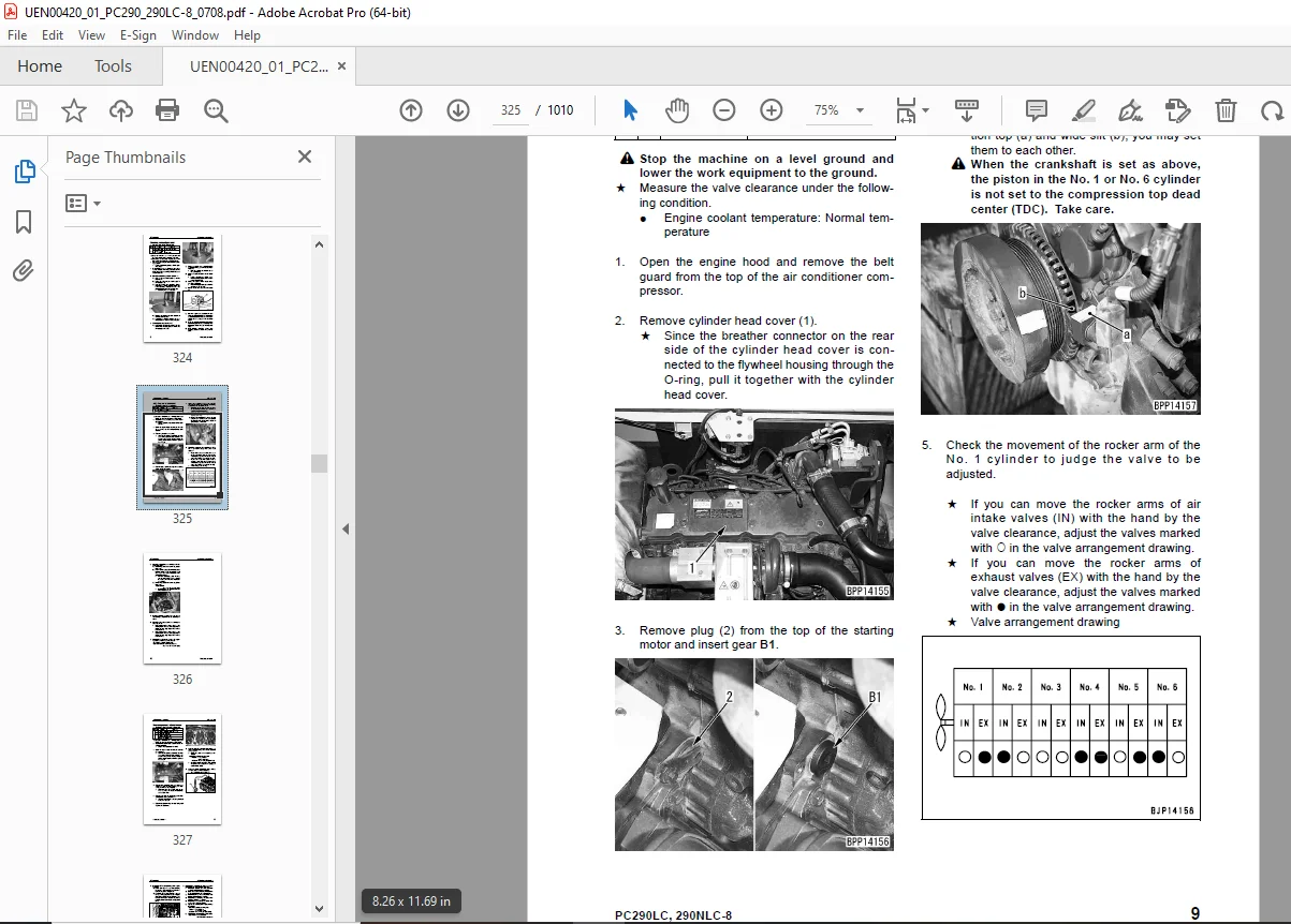
Adjusting valve clearance 325
Measuring compression pressure . 327
Measuring blow-by pressure . 329
Measuring engine oil pressure 330
Handling fuel system parts . 331
Releasing residual pressure from fuel system . 331
Measuring fuel pressure 332
Measuring fuel return rate and leakage . 334
Bleeding air from fuel circuit . 336
Checking fuel circuit for leakage 338
Checking and adjusting air conditioner compressor belt tension . 339
Measuring swing circle bearing clearance . 340
Checking and adjusting track shoe tension 341
Measuring and adjusting oil pressure in work equipment, swing, and travel circuits . 343
Measuring control circuit basic pressure . 346
Measuring and adjusting oil pressure in pump PC control circuit 347
Measuring and adjusting oil pressure in pump LS control circuit 350
Measuring solenoid valve output pressure . 354
Measuring PPC valve output pressure 357
Adjusting play of work equipment and swing PPC valves 359
Checking parts which cause hydraulic drift of work equipment . 360
Releasing residual pressure from hydraulic circuit . 362
Measuring oil leakage 363
Bleeding air from each part 366
Checking cab tipping stopper . 369
Adjusting mirrors 370
30 Testing and adjusting . 373
Testing and adjusting, Part 2 373
Testing and adjusting, Part 2 374
Special functions of machine monitor . 374
30 Testing and adjusting . 431
Testing and adjusting, Part 3 431
Testing and adjusting, Part 3 432
Handling high-voltage circuit of engine controller . 432
Preparation work for troubleshooting of electrical system 433
Procedure for testing diodes . 437
Pm Clinic service 439
40 Troubleshooting . 447
General information on troubleshooting . 447
General information on troubleshooting . 448
Points to remember when troubleshooting 448
Sequence of events in troubleshooting 449
Check before troubleshooting . 450
Classification and procedures for troubleshooting 451
How to read electric wire code . 455
Connection table for connector pin numbers . 458
T-boxes and T-adapters table . 481
40 Troubleshooting . 485
Troubleshooting by failure code (Display of code), Part 1 485
Troubleshooting by failure code (Display of code), Part 1 487
Failure codes table 487
Before carrying out troubleshooting when failure code is displayed . 492
Information in troubleshooting table . 496
Failure code [989L00] Engine Controller Lock Caution 1 . 498
Failure code [989M00] Engine Controller Lock Caution 2 . 498
Failure code [989N00] Engine Controller Lock Caution 3 . 499
Failure code [AA10NX] Air Cleaner Clogging . 499
Failure code [AB00KE] Charge Voltage Low . 500
Failure code [B@BAZG] Eng Oil Press. Low . 502
Failure code [B@BAZK] Eng Oil Level Low 502
Failure code [B@BCNS] Eng Water Overheat . 503
Failure code [B@BCZK] Eng Water Level Low 503
Failure code [B@HANS] Hydr Oil Overheat 504
Failure code [CA111] EMC Critical Internal Failure . 504
Failure code [CA115] Eng Ne and Bkup Speed Sens Error 505
Failure code [CA122] Chg Air Press Sensor High Error . 506
Failure code [CA123] Chg Air Press Sensor Low Error 508
Failure code [CA131] Throttle Sensor High Error 510
Failure code [CA132] Throttle Sensor Low Error . 512
Failure code [CA144] Coolant Temp Sens High Error 514
Failure code [CA145] Coolant Temp Sens Low Error . 516
Failure code [CA153] Chg Air Temp Sensor High Error 518
Failure code [CA154] Chg Air Temp Sensor Low Error . 520
Failure code [CA155] Chg Air Temp High Speed Derate 522
Failure code [CA187] Sens Supply 2 Volt Low Error 524
Failure code [CA221] Ambient Press Sens High Error . 526
Failure code [CA222] Ambient Press Sens Low Error 528
Failure code [CA227] Sens Supply 2 Volt High Error . 530
Failure code [CA234] Eng Overspeed . 531
Failure code [CA238] Ne Speed Sens Supply Volt Error . 532
Failure code [CA271] IMV/PCV1 Short Error 533
Failure code [CA272] IMV/PCV1 Open Error . 534
Failure code [CA322] Inj #1 (L#1) Open/Short Error . 536
Failure code [CA323] Inj #5 (L#5) Open/Short Error . 538
Failure code [CA324] Inj #3 (L#3) Open/Short Error . 540
Failure code [CA325] Inj #6 (L#6) Open/Short Error . 542
Failure code [CA331] Inj #2 (L#2) Open/Short Error . 544
Failure code [CA332] Inj #4 (L#4) Open/Short Error . 546
40 Troubleshooting . 549
Troubleshooting by failure code (Display of code), Part 2 549
Troubleshooting by failure code (Display of code), Part 2 551
Failure code [CA342] Calibration Code Incompatibility 551
Failure code [CA351] Injectors Drive Circuit Error . 552
Failure code [CA352] Sens Supply 1 Volt Low Error 554
Failure code [CA386] Sens Supply 1 Volt High Error . 556
Failure code [CA428] Water in Fuel Sensor High Error . 558
Failure code [CA429] Water in Fuel Sensor Low Error 560
Failure code [CA435] Eng Oil Press Sw Error 562
Failure code [CA441] Battery Voltage Low Error . 563
Failure code [CA442] Battery Voltage High Error 566
Failure code [CA449] Rail Press Very High Error 568
Failure code [CA451] Rail Press Sensor High Error 570
Failure code [CA452] Rail Press Sensor Low Error . 572
Failure code [CA488] Chg Air Temp High Torque Derate . 574
Failure code [CA553] Rail Press High Error . 574
Failure code [CA559] Rail Press Low Error 575
Failure code [CA689] Eng Ne Speed Sensor Error . 576
Failure code [CA731] Eng Bkup Speed Sens Phase Error . 578
Failure code [CA757] All Continuous Data Lost Error 580
Failure code [CA778] Eng Bkup Speed Sensor Error . 582
Failure code [CA1633] KOMNET Datalink Timeout Error 584
Failure code [CA2185] Throt Sens Sup Volt High Error . 586
Failure code [CA2186] Throt Sens Sup Volt Low Error 587
Failure code [CA2249] Rail Press Very Low Error 588
Failure code [CA2311] IMV Solenoid Error . 590
Failure code [CA2555] Grid Htr Relay Volt High Error . 592
Failure code [CA2556] Grid Htr Relay Volt Low Error 594
Failure code [D19JKZ] Personal Code Relay Abnormality 596
Failure code [D862KA] GPS Antenna Discon . 598
Failure code [DA25KP] 5V Sensor 1 Power Abnormality 599
Failure code [DA29KQ] Model Selection Abnormality 606
40 Troubleshooting . 609
Troubleshooting by failure code (Display of code), Part 3 609
Troubleshooting by failure code (Display of code), Part 3 612
Failure code [DA2RMC] CAN Discon (Pump Con Detected) . 612
Failure code [DAFGMC] GPS Module Error . 614
Failure code [DAFRMC] CAN Discon (Monitor Detected) 616
Failure code [DGH2KB] Hydr Oil Sensor Short 618
Failure code [DHPAMA] F Pump Press Sensor Abnormality 620
Failure code [DHPBMA] R Pump Press Sensor Abnormality 622
Failure code [DHS3MA] Arm Curl PPC Press Sensor Abnormality 624
Failure code [DHS4MA] Bucket Curl PPC Press Sensor Abnormality . 626
Failure code [DHS8MA] Boom Raise PPC Press Sensor Abnormality 628
Failure code [DHSAMA] Swing RH PPC Press Sensor Abnormality 630
Failure code [DHSBMA] Swing LH PPC Press Sensor Abnormality 632
Failure code [DHSDMA] Bucket Dump PPC Press Sensor Abnormality . 634
Failure code [DHX1MA] Overload Sensor Abnormality (Analog) . 636
Failure code [DW43KA] Travel Speed Sol Discon 638
Failure code [DW43KB] Travel Speed Sol Short . 640
Failure code [DW45KA] Swing Brake Sol Discon . 642
Failure code [DW45KB] Swing Brake Sol Short 644
Failure code [DW91KA] Travel Junction Sol Discon . 646
Failure code [DW91KB] Travel Junction Sol Short 648
Failure code [DWA2KA] Service Sol Discon . 650
Failure code [DWA2KB] Service Sol Short 651
Failure code [DWK0KA] 2-stage Relief Sol Discon 652
Failure code [DWK0KB] 2-stage Relief Sol Short . 654
40 Troubleshooting . 657
Troubleshooting by failure code (Display of code), Part 4 657
Troubleshooting by failure code (Display of code), Part 4 660
Failure code [DXA8KA] PC-EPC (F) Sol Discon 660
Failure code [DXA8KB] PC-EPC (F) Sol Short . 662
Failure code [DXA9KA] PC-EPC (R) Sol Discon 664
Failure code [DXA9KB] PC-EPC (R) Sol Short . 666
Failure code [DXE0KA] LS-EPC Sol Discon 668
Failure code [DXE0KB] LS-EPC Sol Short . 670
Failure code [DXE4KA] Service Current EPC Discon . 672
Failure code [DXE4KB] Service Current EPC Short 674
Failure code [DXE5KA] Merge-divider Main Sol Discon 676
Failure code [DXE5KB] Merge-divider Main Sol Short . 678
Failure code [DXE6KA] Merge-divider LS Sol Discon 680
Failure code [DXE6KB] Merge-divider LS Sol Short . 682
Failure code [DY20KA] Wiper Working Abnormality 684
Failure code [DY20MA] Wiper Parking Abnormality 686
Failure code [DY2CKA] Washer Drive Discon 688
Failure code [DY2CKB] Washer Drive Short . 690
Failure code [DY2DKB] Wiper Drive (For) Short 692
Failure code [DY2EKB] Wiper Drive (Rev) Short 694
40 Troubleshooting . 697
Troubleshooting of electrical system (E-mode) 697
Troubleshooting of electrical system (E-mode) 699
Before carrying out troubleshooting of electrical system . 699
Information in troubleshooting table . 701
E-1 When starting switch turned ON, machine monitor displays nothing . 702
E-2 When starting switch turned ON (before starting engine), basic check item lights up 704
E-3 Engine does not start (Engine does not turn) . 707
E-4 Preheater does not operate . 710
E-5 Automatic warm-up system does not operate (in cold season) . 712
E-6 All work equipment, swing, and travel mechanism do not move or cannot be locked 714
E-7 Precaution lights up while engine is running . 716
E-8 Emergency stop item lights up while engine is running 721
E-9 Engine coolant temperature gauge does not indicate normally 722
E-10 Hydraulic oil temperature gauge does not indicate normally 723
E-11 Fuel level gauge does not indicate normally . 725
E-12 Contents of display by machine monitor are different from applicable machine 727
E-13 Machine monitor does not display some items . 727
E-14 Function switch does not work . 727
E-15 Auto-decelerator does not operate normally 728
E-16 Working mode does not change 729
E-17 Travel speed does not change 730
E-18 Alarm buzzer cannot be stopped 731
E-19 Windshield wiper and window washer do not operate . 732
E-20 Power maximizing function does not operate normally . 734
E-21 Swing holding brake does not operate normally . 736
E-22 Travel alarm does not sound or does not stop sounding . 738
E-23 Air conditioner does not operate normally (including air conditioner abnormality record) 740
E-24 When starting switch is turned OFF, service meter is not displayed 752
E-25 Machine monitor cannot be set in service mode . 752
E-26 Monitoring function does not display lever control signal normally 753
E-27 KOMTRAX system does not operate normally 761
40 Troubleshooting . 763
Troubleshooting of hydraulic and mechanical system (H-mode) 763
Troubleshooting of hydraulic and mechanical system (H-mode) 766
System diagram of hydraulic and mechanical system 766
Information in troubleshooting table . 768
H-1 Speed or power of whole work equipment, swing, and travel is low . 769
H-2 Engine speed lowers extremely or engine stalls . 771
H-3 Work equipment, swing, and travel systems do not work 772
H-4 Abnormal sound comes out from around hydraulic pump 772
H-5 Auto-decelerator does not operate 773
H-6 Fine control performance or response is low 773
H-7 Speed or power of boom is low 774
H-8 Speed or power of arm is low . 775
H-9 Speed or power of bucket is low 776
H-10 Work equipment does not move singly . 776
H-11 Hydraulic drift of work equipment is large 777
H-12 Time lag of work equipment is large . 779
H-13 When part of work equipment is relieved singly, other parts of work equipment move 779
H-14 Power maximizing function does not work . 780
H-15 In compound operation of work equipment, speed of part loaded more is low . 780
H-16 When machine swings and raises boom simultaneously, boom rising speed is low 781
H-17 When machine swings and travels simultaneously, travel speed lowers largely . 781
H-18 Machine deviates during travel 782
H-19 Travel speed is low . 783
H-20 Machine is not steered well or steering power is low 784
H-21 Travel speed does not change or travel speed is low/high 785
H-22 Travel system does not move (only one side) . 786
H-23 Upper structure does not swing 787
H-24 Swing acceleration or swing speed is low 789
H-25 Upper structure overruns remarkably when it stops swinging 790
H-26 Large shock is made when upper structure stops swinging . 791
H-27 Large sound is made when upper structure stops swinging . 791
H-28 Hydraulic drift of swing is large . 792
H-29 Attachment circuit is not changed . 793
H-30 Oil flow in attachment circuit cannot be controlled . 793
40 Troubleshooting . 795
Troubleshooting of engine (S-mode) . 795
Troubleshooting of engine (S-mode) . 797
Method of using troubleshooting chart 797
S-1 Starting performance is poor . 800
S-2 Engine does not start 801
S-3 Engine does not pick up smoothly . 804
S-4 Engine stops during operations . 805
S-5 Engine does not rotate smoothly 806
S-6 Engine lack output (or lacks power) 807
S-7 Exhaust smoke is black (incomplete combustion) . 808
S-8 Oil consumption is excessive (or exhaust smoke is blue) 809
S-9 Oil becomes contaminated quickly . 810
S-10 Fuel consumption is excessive . 811
S-11 Oil is in coolant (or coolant spurts back or coolant level goes down) . 812
S-12 Oil pressure drops 813
S-13 Oil level rises (Entry of coolant/fuel) . 814
S-14 Coolant temperature becomes too high (overheating) 815
S-15 Abnormal noise is made 816
S-16 Vibration is excessive 817
50 Disassembly and assembly 819
General information on disassembly and assembly 819
General information on disassembly and assembly 820
How to read this manual 820
Coating materials list . 822
Special tool list 825
Sketches of special tools 830
50 Disassembly and assembly 833
Engine and cooling system 833
Engine and cooling system 834
Removal and installation of fuel supply pump assembly 834
Removal and installation of fuel injector assembly . 836
Removal and installation of engine front seal 843
Removal and installation of engine rear seal . 846
Removal and installation of cylinder head assembly . 849
Removal and installation of radiator assembly 861
Removal and installation of hydraulic oil cooler assembly 864
Removal and installation of aftercooler assembly . 866
Removal and installation of fuel cooler assembly . 868
Removal and installation of engine and hydraulic pump assembly . 869
50 Disassembly and assembly 879
Power train 879
Power train 880
Removal and installation of final drive assembly . 880
Disassembly and assembly of final drive assembly . 881
Removal and installation of swing motor and swing machinery assembly . 890
Disassembly and assembly of swing motor and swing machinery assembly . 892
Removal and installation of swing circle assembly 901
50 Disassembly and assembly 903
Undercarriage and frame 903
Undercarriage and frame 904
Disassembly and assembly of carrier roller assembly 904
Disassembly and assembly of track roller assembly 905
Disassembly and assembly of idler assembly . 906
Disassembly and assembly of recoil spring assembly . 909
Removal and installation of sprocket . 911
Expansion and installation of track shoe assembly 912
Removal and installation of revolving frame assembly . 914
Removal and installation of counterweight assembly . 916
50 Disassembly and assembly 919
Hydraulic system . 919
Hydraulic system . 920
Removal and installation of center swivel joint assembly . 920
Disassembly and assembly of center swivel joint assembly . 922
Removal and installation of hydraulic tank assembly 923
Removal and installation of control valve assembly . 926
Disassembly and assembly of control valve assembly . 931
Removal and installation of hydraulic pump assembly 935
Removal and installation of oil seal in hydraulic pump input shaft . 939
Disassembly and assembly of work equipment PPC valve assembly 940
Disassembly and assembly of travel PPC valve assembly 941
Disassembly and assembly of hydraulic cylinder assembly 942
50 Disassembly and assembly 949
Work equipment . 949
Work equipment . 950
Removal and installation of work equipment assembly 950
50 Disassembly and assembly 955
Cab and its attachments 955
Cab and its attachments 956
Removal and installation of operator’s cab assembly 956
Removal and installation of operator cab glass (stuck glass) . 959
Removal and installation of front window assembly 969
Removal and installation of floor frame assembly . 976
50 Disassembly and assembly 981
Electrical system 981
Electrical system 982
Removal and installation of air conditioner unit assembly 982
Removal and installation of KOMTRAX communication modem assembly . 985
Removal and installation of monitor assembly . 986
Removal and installation of pump controller assembly . 988
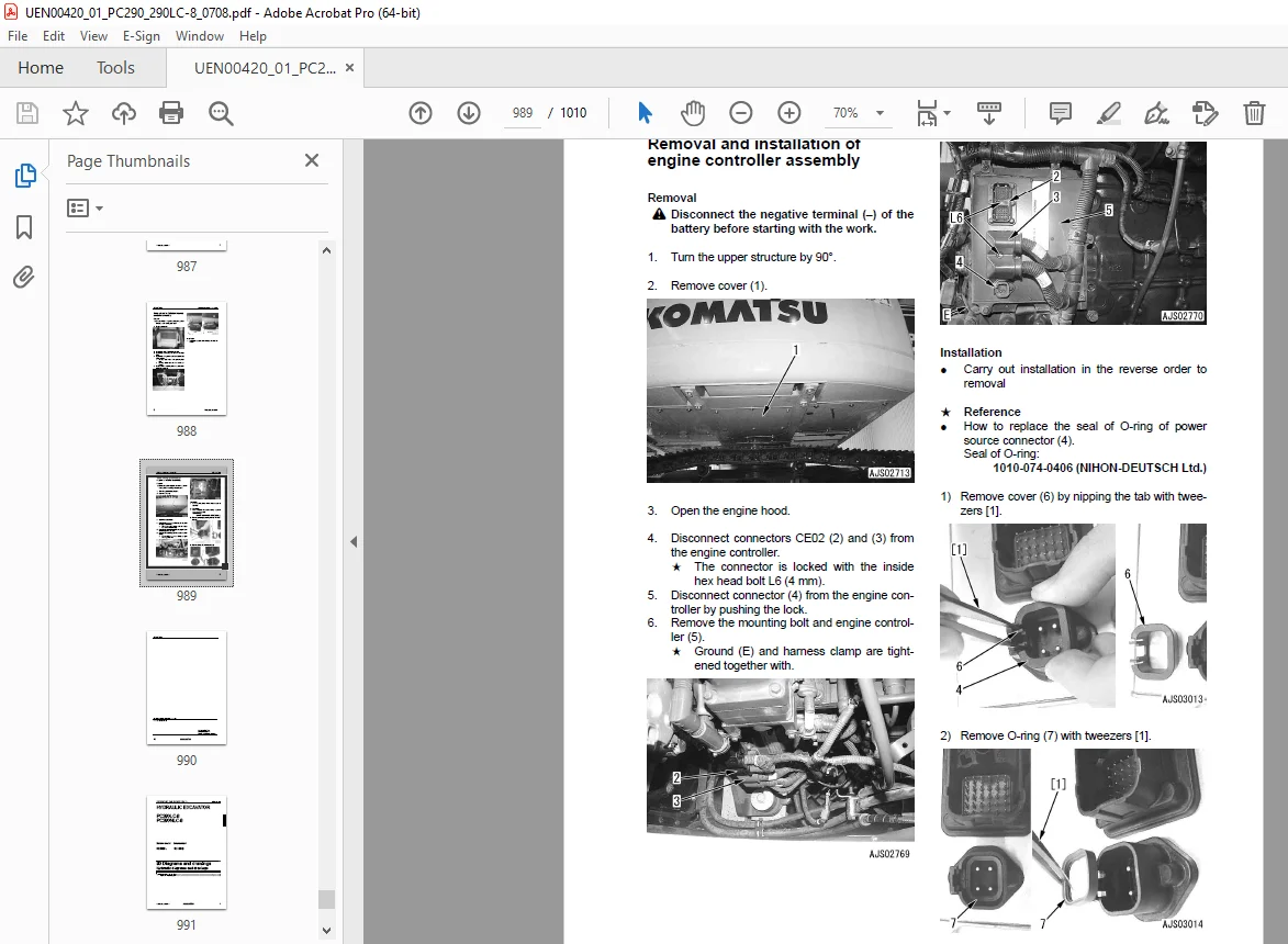
Removal and installation of engine controller assembly . 989
90 Diagrams and drawings . 991
Hydraulic diagrams and drawings 991
Hydraulic diagrams and drawings 993
Hydraulic circuit diagram 993
90 Diagrams and drawings . 997
Electrical diagrams and drawings . 997
Electrical circuit diagram . 999
Electrical circuit diagram (1/5) . 999
Electrical circuit diagram (2/5) .1001
Electrical circuit diagram (3/5) .1003
Electrical circuit diagram (4/5) .1005
Electrical circuit diagram (5/5) .1007
DESCRIPTION:
Komatsu PC290LC-8,PC290NLC-8 Hydraulic Excavator Shop Manual UEN00420-01 – PDF DOWNLOAD
- PC290LC- 10001 and up
- PC290NLC- 10001 and up
How to read the shop manual
1. Composition of shop manual
This shop manual contains the necessary technical information for services performed in a workshop.
For ease of understanding, the manual is divided into the following sections.
00. Index and foreword
This section explains the shop manuals list, table of contents, safety, and basic information.
01. Specification
This section explains the specifications of the machine.
10. Structure, function and maintenance standard
This section explains the structure, function, and maintenance standard values of each component.
The structure and function sub-section explains the structure and function of each component. It
serves not only to give an understanding of the structure, but also serves as reference material for
troubleshooting. The maintenance standard sub-section explains the criteria and remedies for disassembly
and service.
20. Standard value table
This section explains the standard values for new machine and judgement criteria for testing,
adjusting, and troubleshooting. This standard value table is used to check the standard values in
testing and adjusting and to judge parts in troubleshooting.
30. Testing and adjusting
This section explains measuring instruments and measuring methods for testing and adjusting, and
method of adjusting each part. The standard values and judgement criteria for testing and adjusting
are explained in Testing and adjusting.
40. Troubleshooting
This section explains how to find out failed parts and how to repair them. The troubleshooting is
divided by failure modes. The “S mode” of the troubleshooting related to the engine may be also
explained in the Chassis volume and Engine volume. In this case, see the Chassis volume.
50. Disassembly and assembly
This section explains the special tools and procedures for removing, installing, disassembling, and
assembling each component, as well as precautions for them. In addition, tightening torque and
quantity and weight of coating material, oil, grease, and coolant necessary for the work are also
explained.
90. Diagrams and drawings (chassis volume)/Repair and replacement of parts (engine volume)
q Chassis volume
This section gives hydraulic circuit diagrams and electrical circuit diagrams.
q Engine volume
This section explains the method of reproducing, repairing, and replacing parts.
G.B 30/12/24


